EP1109218B1 - Heat conducting mold and manufacturing method thereof - Google Patents
Heat conducting mold and manufacturing method thereof Download PDFInfo
- Publication number
- EP1109218B1 EP1109218B1 EP00310713A EP00310713A EP1109218B1 EP 1109218 B1 EP1109218 B1 EP 1109218B1 EP 00310713 A EP00310713 A EP 00310713A EP 00310713 A EP00310713 A EP 00310713A EP 1109218 B1 EP1109218 B1 EP 1109218B1
- Authority
- EP
- European Patent Office
- Prior art keywords
- boron nitride
- nitride powder
- heat
- heat conductive
- sheet
- Prior art date
- Legal status (The legal status is an assumption and is not a legal conclusion. Google has not performed a legal analysis and makes no representation as to the accuracy of the status listed.)
- Expired - Lifetime
Links
- 238000004519 manufacturing process Methods 0.000 title claims description 15
- 239000000843 powder Substances 0.000 claims description 90
- 229910052582 BN Inorganic materials 0.000 claims description 89
- PZNSFCLAULLKQX-UHFFFAOYSA-N Boron nitride Chemical compound N#B PZNSFCLAULLKQX-UHFFFAOYSA-N 0.000 claims description 89
- 229920000642 polymer Polymers 0.000 claims description 38
- 230000005291 magnetic effect Effects 0.000 claims description 33
- 239000000203 mixture Substances 0.000 claims description 32
- 238000000034 method Methods 0.000 claims description 25
- 239000002904 solvent Substances 0.000 claims description 11
- 239000004642 Polyimide Substances 0.000 claims description 8
- 229920001721 polyimide Polymers 0.000 claims description 8
- 229920002379 silicone rubber Polymers 0.000 claims description 6
- 229920002635 polyurethane Polymers 0.000 claims description 5
- 239000004814 polyurethane Substances 0.000 claims description 5
- 239000004593 Epoxy Substances 0.000 claims description 4
- 239000000835 fiber Substances 0.000 claims description 4
- 230000008569 process Effects 0.000 claims description 3
- 229920005989 resin Polymers 0.000 description 14
- 239000011347 resin Substances 0.000 description 14
- 229920001971 elastomer Polymers 0.000 description 12
- 239000002245 particle Substances 0.000 description 12
- 239000005060 rubber Substances 0.000 description 12
- -1 granular Substances 0.000 description 10
- 239000004065 semiconductor Substances 0.000 description 9
- 229920002725 thermoplastic elastomer Polymers 0.000 description 9
- 238000002156 mixing Methods 0.000 description 8
- 229910052751 metal Inorganic materials 0.000 description 7
- 239000002184 metal Substances 0.000 description 7
- PNEYBMLMFCGWSK-UHFFFAOYSA-N Alumina Chemical compound [O-2].[O-2].[O-2].[Al+3].[Al+3] PNEYBMLMFCGWSK-UHFFFAOYSA-N 0.000 description 6
- VLKZOEOYAKHREP-UHFFFAOYSA-N n-Hexane Chemical compound CCCCCC VLKZOEOYAKHREP-UHFFFAOYSA-N 0.000 description 6
- 229920001955 polyphenylene ether Polymers 0.000 description 6
- 229920001187 thermosetting polymer Polymers 0.000 description 6
- 239000012298 atmosphere Substances 0.000 description 5
- 230000004907 flux Effects 0.000 description 5
- SECXISVLQFMRJM-UHFFFAOYSA-N N-Methylpyrrolidone Chemical compound CN1CCCC1=O SECXISVLQFMRJM-UHFFFAOYSA-N 0.000 description 4
- 239000004721 Polyphenylene oxide Substances 0.000 description 4
- XLOMVQKBTHCTTD-UHFFFAOYSA-N Zinc monoxide Chemical compound [Zn]=O XLOMVQKBTHCTTD-UHFFFAOYSA-N 0.000 description 4
- 238000001125 extrusion Methods 0.000 description 4
- 238000009413 insulation Methods 0.000 description 4
- 239000007788 liquid Substances 0.000 description 4
- 230000005855 radiation Effects 0.000 description 4
- 239000007787 solid Substances 0.000 description 4
- 239000000945 filler Substances 0.000 description 3
- 238000010438 heat treatment Methods 0.000 description 3
- 150000002739 metals Chemical class 0.000 description 3
- 229920013636 polyphenyl ether polymer Polymers 0.000 description 3
- 239000004945 silicone rubber Substances 0.000 description 3
- 229920005992 thermoplastic resin Polymers 0.000 description 3
- 229910017083 AlN Inorganic materials 0.000 description 2
- PIGFYZPCRLYGLF-UHFFFAOYSA-N Aluminum nitride Chemical compound [Al]#N PIGFYZPCRLYGLF-UHFFFAOYSA-N 0.000 description 2
- OKTJSMMVPCPJKN-UHFFFAOYSA-N Carbon Chemical compound [C] OKTJSMMVPCPJKN-UHFFFAOYSA-N 0.000 description 2
- RTZKZFJDLAIYFH-UHFFFAOYSA-N Diethyl ether Chemical compound CCOCC RTZKZFJDLAIYFH-UHFFFAOYSA-N 0.000 description 2
- 229920000459 Nitrile rubber Polymers 0.000 description 2
- 229920002845 Poly(methacrylic acid) Polymers 0.000 description 2
- 239000004698 Polyethylene Substances 0.000 description 2
- XUIMIQQOPSSXEZ-UHFFFAOYSA-N Silicon Chemical compound [Si] XUIMIQQOPSSXEZ-UHFFFAOYSA-N 0.000 description 2
- PPBRXRYQALVLMV-UHFFFAOYSA-N Styrene Chemical compound C=CC1=CC=CC=C1 PPBRXRYQALVLMV-UHFFFAOYSA-N 0.000 description 2
- 239000000956 alloy Substances 0.000 description 2
- 229910045601 alloy Inorganic materials 0.000 description 2
- WNROFYMDJYEPJX-UHFFFAOYSA-K aluminium hydroxide Chemical compound [OH-].[OH-].[OH-].[Al+3] WNROFYMDJYEPJX-UHFFFAOYSA-K 0.000 description 2
- 229910021502 aluminium hydroxide Inorganic materials 0.000 description 2
- UMIVXZPTRXBADB-UHFFFAOYSA-N benzocyclobutene Chemical compound C1=CC=C2CCC2=C1 UMIVXZPTRXBADB-UHFFFAOYSA-N 0.000 description 2
- 229910052797 bismuth Inorganic materials 0.000 description 2
- 229920005549 butyl rubber Polymers 0.000 description 2
- 239000000919 ceramic Substances 0.000 description 2
- 238000001816 cooling Methods 0.000 description 2
- 238000009998 heat setting Methods 0.000 description 2
- 239000004850 liquid epoxy resins (LERs) Substances 0.000 description 2
- 239000000463 material Substances 0.000 description 2
- 150000001247 metal acetylides Chemical class 0.000 description 2
- 229910000000 metal hydroxide Inorganic materials 0.000 description 2
- 150000004692 metal hydroxides Chemical class 0.000 description 2
- 229910044991 metal oxide Inorganic materials 0.000 description 2
- 150000004706 metal oxides Chemical class 0.000 description 2
- 238000000465 moulding Methods 0.000 description 2
- 150000004767 nitrides Chemical class 0.000 description 2
- 229920000573 polyethylene Polymers 0.000 description 2
- 229920001296 polysiloxane Polymers 0.000 description 2
- 239000004800 polyvinyl chloride Substances 0.000 description 2
- 229920000915 polyvinyl chloride Polymers 0.000 description 2
- 239000002243 precursor Substances 0.000 description 2
- 229910052710 silicon Inorganic materials 0.000 description 2
- 239000010703 silicon Substances 0.000 description 2
- HBMJWWWQQXIZIP-UHFFFAOYSA-N silicon carbide Chemical compound [Si+]#[C-] HBMJWWWQQXIZIP-UHFFFAOYSA-N 0.000 description 2
- 229910010271 silicon carbide Inorganic materials 0.000 description 2
- 229920003048 styrene butadiene rubber Polymers 0.000 description 2
- 239000000758 substrate Substances 0.000 description 2
- 238000004381 surface treatment Methods 0.000 description 2
- 229920006305 unsaturated polyester Polymers 0.000 description 2
- 239000002966 varnish Substances 0.000 description 2
- 239000011787 zinc oxide Substances 0.000 description 2
- ROGIWVXWXZRRMZ-UHFFFAOYSA-N 2-methylbuta-1,3-diene;styrene Chemical compound CC(=C)C=C.C=CC1=CC=CC=C1 ROGIWVXWXZRRMZ-UHFFFAOYSA-N 0.000 description 1
- 239000004953 Aliphatic polyamide Substances 0.000 description 1
- 239000004709 Chlorinated polyethylene Substances 0.000 description 1
- 229920000089 Cyclic olefin copolymer Polymers 0.000 description 1
- 239000004641 Diallyl-phthalate Substances 0.000 description 1
- VGGSQFUCUMXWEO-UHFFFAOYSA-N Ethene Chemical compound C=C VGGSQFUCUMXWEO-UHFFFAOYSA-N 0.000 description 1
- 239000005977 Ethylene Substances 0.000 description 1
- 229920000181 Ethylene propylene rubber Polymers 0.000 description 1
- 244000043261 Hevea brasiliensis Species 0.000 description 1
- 229920000106 Liquid crystal polymer Polymers 0.000 description 1
- 239000004977 Liquid-crystal polymers (LCPs) Substances 0.000 description 1
- 239000002033 PVDF binder Substances 0.000 description 1
- ISWSIDIOOBJBQZ-UHFFFAOYSA-N Phenol Chemical compound OC1=CC=CC=C1 ISWSIDIOOBJBQZ-UHFFFAOYSA-N 0.000 description 1
- 239000004952 Polyamide Substances 0.000 description 1
- 239000004962 Polyamide-imide Substances 0.000 description 1
- 239000005062 Polybutadiene Substances 0.000 description 1
- 239000004695 Polyether sulfone Substances 0.000 description 1
- 229920000265 Polyparaphenylene Polymers 0.000 description 1
- 239000004734 Polyphenylene sulfide Substances 0.000 description 1
- 239000004793 Polystyrene Substances 0.000 description 1
- 239000004372 Polyvinyl alcohol Substances 0.000 description 1
- 229920001328 Polyvinylidene chloride Polymers 0.000 description 1
- BLRPTPMANUNPDV-UHFFFAOYSA-N Silane Chemical compound [SiH4] BLRPTPMANUNPDV-UHFFFAOYSA-N 0.000 description 1
- 229920002125 Sokalan® Polymers 0.000 description 1
- 239000002174 Styrene-butadiene Substances 0.000 description 1
- RTAQQCXQSZGOHL-UHFFFAOYSA-N Titanium Chemical compound [Ti] RTAQQCXQSZGOHL-UHFFFAOYSA-N 0.000 description 1
- 229920006311 Urethane elastomer Polymers 0.000 description 1
- 238000002441 X-ray diffraction Methods 0.000 description 1
- 229920000122 acrylonitrile butadiene styrene Polymers 0.000 description 1
- 238000004220 aggregation Methods 0.000 description 1
- 230000002776 aggregation Effects 0.000 description 1
- 125000001931 aliphatic group Chemical group 0.000 description 1
- 229920003231 aliphatic polyamide Polymers 0.000 description 1
- 150000001336 alkenes Chemical class 0.000 description 1
- 239000004411 aluminium Substances 0.000 description 1
- 229910052782 aluminium Inorganic materials 0.000 description 1
- XAGFODPZIPBFFR-UHFFFAOYSA-N aluminium Chemical compound [Al] XAGFODPZIPBFFR-UHFFFAOYSA-N 0.000 description 1
- 239000004760 aramid Substances 0.000 description 1
- 229920003235 aromatic polyamide Polymers 0.000 description 1
- QUDWYFHPNIMBFC-UHFFFAOYSA-N bis(prop-2-enyl) benzene-1,2-dicarboxylate Chemical compound C=CCOC(=O)C1=CC=CC=C1C(=O)OCC=C QUDWYFHPNIMBFC-UHFFFAOYSA-N 0.000 description 1
- MTAZNLWOLGHBHU-UHFFFAOYSA-N butadiene-styrene rubber Chemical compound C=CC=C.C=CC1=CC=CC=C1 MTAZNLWOLGHBHU-UHFFFAOYSA-N 0.000 description 1
- 229910052799 carbon Inorganic materials 0.000 description 1
- 238000006243 chemical reaction Methods 0.000 description 1
- YACLQRRMGMJLJV-UHFFFAOYSA-N chloroprene Chemical compound ClC(=C)C=C YACLQRRMGMJLJV-UHFFFAOYSA-N 0.000 description 1
- 238000004140 cleaning Methods 0.000 description 1
- 230000006835 compression Effects 0.000 description 1
- 238000007906 compression Methods 0.000 description 1
- 239000011231 conductive filler Substances 0.000 description 1
- 229920001577 copolymer Polymers 0.000 description 1
- 239000007822 coupling agent Substances 0.000 description 1
- 238000005238 degreasing Methods 0.000 description 1
- 230000005292 diamagnetic effect Effects 0.000 description 1
- 239000002889 diamagnetic material Substances 0.000 description 1
- 229910003460 diamond Inorganic materials 0.000 description 1
- 239000010432 diamond Substances 0.000 description 1
- 238000009792 diffusion process Methods 0.000 description 1
- 238000009826 distribution Methods 0.000 description 1
- 230000000694 effects Effects 0.000 description 1
- 150000002148 esters Chemical class 0.000 description 1
- 239000005038 ethylene vinyl acetate Substances 0.000 description 1
- 239000012530 fluid Substances 0.000 description 1
- 229910002804 graphite Inorganic materials 0.000 description 1
- 239000010439 graphite Substances 0.000 description 1
- 239000004519 grease Substances 0.000 description 1
- 150000004820 halides Chemical class 0.000 description 1
- 230000017525 heat dissipation Effects 0.000 description 1
- 230000006872 improvement Effects 0.000 description 1
- 230000010354 integration Effects 0.000 description 1
- 229920000554 ionomer Polymers 0.000 description 1
- 229920003049 isoprene rubber Polymers 0.000 description 1
- CPLXHLVBOLITMK-UHFFFAOYSA-N magnesium oxide Inorganic materials [Mg]=O CPLXHLVBOLITMK-UHFFFAOYSA-N 0.000 description 1
- 239000000395 magnesium oxide Substances 0.000 description 1
- AXZKOIWUVFPNLO-UHFFFAOYSA-N magnesium;oxygen(2-) Chemical compound [O-2].[Mg+2] AXZKOIWUVFPNLO-UHFFFAOYSA-N 0.000 description 1
- 230000005415 magnetization Effects 0.000 description 1
- 239000011159 matrix material Substances 0.000 description 1
- 238000005259 measurement Methods 0.000 description 1
- 150000004702 methyl esters Chemical class 0.000 description 1
- 229920003052 natural elastomer Polymers 0.000 description 1
- 229920001194 natural rubber Polymers 0.000 description 1
- 150000002825 nitriles Chemical class 0.000 description 1
- JRZJOMJEPLMPRA-UHFFFAOYSA-N olefin Natural products CCCCCCCC=C JRZJOMJEPLMPRA-UHFFFAOYSA-N 0.000 description 1
- 229920001643 poly(ether ketone) Polymers 0.000 description 1
- 229920001200 poly(ethylene-vinyl acetate) Polymers 0.000 description 1
- 229920002285 poly(styrene-co-acrylonitrile) Polymers 0.000 description 1
- 229920002492 poly(sulfone) Polymers 0.000 description 1
- 229920002239 polyacrylonitrile Polymers 0.000 description 1
- 229920002647 polyamide Polymers 0.000 description 1
- 229920002312 polyamide-imide Polymers 0.000 description 1
- 229920002857 polybutadiene Polymers 0.000 description 1
- 239000004417 polycarbonate Substances 0.000 description 1
- 229920000515 polycarbonate Polymers 0.000 description 1
- 229920000728 polyester Polymers 0.000 description 1
- 229920000570 polyether Polymers 0.000 description 1
- 229920006393 polyether sulfone Polymers 0.000 description 1
- 229920000139 polyethylene terephthalate Polymers 0.000 description 1
- 239000005020 polyethylene terephthalate Substances 0.000 description 1
- 229920001470 polyketone Polymers 0.000 description 1
- 229920000306 polymethylpentene Polymers 0.000 description 1
- 239000011116 polymethylpentene Substances 0.000 description 1
- 229920000098 polyolefin Polymers 0.000 description 1
- 229920000069 polyphenylene sulfide Polymers 0.000 description 1
- 229920002223 polystyrene Polymers 0.000 description 1
- 229920001343 polytetrafluoroethylene Polymers 0.000 description 1
- 239000004810 polytetrafluoroethylene Substances 0.000 description 1
- 229920002689 polyvinyl acetate Polymers 0.000 description 1
- 239000011118 polyvinyl acetate Substances 0.000 description 1
- 229920002451 polyvinyl alcohol Polymers 0.000 description 1
- 239000005033 polyvinylidene chloride Substances 0.000 description 1
- 229920002981 polyvinylidene fluoride Polymers 0.000 description 1
- 239000011164 primary particle Substances 0.000 description 1
- 239000010453 quartz Substances 0.000 description 1
- 239000002994 raw material Substances 0.000 description 1
- 238000010008 shearing Methods 0.000 description 1
- 229910000077 silane Inorganic materials 0.000 description 1
- VYPSYNLAJGMNEJ-UHFFFAOYSA-N silicon dioxide Inorganic materials O=[Si]=O VYPSYNLAJGMNEJ-UHFFFAOYSA-N 0.000 description 1
- 229920002050 silicone resin Polymers 0.000 description 1
- 239000011115 styrene butadiene Substances 0.000 description 1
- 239000013585 weight reducing agent Substances 0.000 description 1
- 239000004711 α-olefin Substances 0.000 description 1
Images


Classifications
-
- H—ELECTRICITY
- H01—ELECTRIC ELEMENTS
- H01L—SEMICONDUCTOR DEVICES NOT COVERED BY CLASS H10
- H01L21/00—Processes or apparatus adapted for the manufacture or treatment of semiconductor or solid state devices or of parts thereof
- H01L21/02—Manufacture or treatment of semiconductor devices or of parts thereof
- H01L21/04—Manufacture or treatment of semiconductor devices or of parts thereof the devices having potential barriers, e.g. a PN junction, depletion layer or carrier concentration layer
- H01L21/48—Manufacture or treatment of parts, e.g. containers, prior to assembly of the devices, using processes not provided for in a single one of the subgroups H01L21/06 - H01L21/326
- H01L21/4814—Conductive parts
- H01L21/4871—Bases, plates or heatsinks
-
- H—ELECTRICITY
- H01—ELECTRIC ELEMENTS
- H01L—SEMICONDUCTOR DEVICES NOT COVERED BY CLASS H10
- H01L23/00—Details of semiconductor or other solid state devices
- H01L23/34—Arrangements for cooling, heating, ventilating or temperature compensation ; Temperature sensing arrangements
- H01L23/36—Selection of materials, or shaping, to facilitate cooling or heating, e.g. heatsinks
- H01L23/373—Cooling facilitated by selection of materials for the device or materials for thermal expansion adaptation, e.g. carbon
- H01L23/3737—Organic materials with or without a thermoconductive filler
-
- H—ELECTRICITY
- H01—ELECTRIC ELEMENTS
- H01L—SEMICONDUCTOR DEVICES NOT COVERED BY CLASS H10
- H01L23/00—Details of semiconductor or other solid state devices
- H01L23/34—Arrangements for cooling, heating, ventilating or temperature compensation ; Temperature sensing arrangements
- H01L23/42—Fillings or auxiliary members in containers or encapsulations selected or arranged to facilitate heating or cooling
- H01L23/433—Auxiliary members in containers characterised by their shape, e.g. pistons
-
- H—ELECTRICITY
- H01—ELECTRIC ELEMENTS
- H01L—SEMICONDUCTOR DEVICES NOT COVERED BY CLASS H10
- H01L2224/00—Indexing scheme for arrangements for connecting or disconnecting semiconductor or solid-state bodies and methods related thereto as covered by H01L24/00
- H01L2224/01—Means for bonding being attached to, or being formed on, the surface to be connected, e.g. chip-to-package, die-attach, "first-level" interconnects; Manufacturing methods related thereto
- H01L2224/10—Bump connectors; Manufacturing methods related thereto
- H01L2224/15—Structure, shape, material or disposition of the bump connectors after the connecting process
- H01L2224/16—Structure, shape, material or disposition of the bump connectors after the connecting process of an individual bump connector
-
- H—ELECTRICITY
- H01—ELECTRIC ELEMENTS
- H01L—SEMICONDUCTOR DEVICES NOT COVERED BY CLASS H10
- H01L2224/00—Indexing scheme for arrangements for connecting or disconnecting semiconductor or solid-state bodies and methods related thereto as covered by H01L24/00
- H01L2224/01—Means for bonding being attached to, or being formed on, the surface to be connected, e.g. chip-to-package, die-attach, "first-level" interconnects; Manufacturing methods related thereto
- H01L2224/26—Layer connectors, e.g. plate connectors, solder or adhesive layers; Manufacturing methods related thereto
- H01L2224/28—Structure, shape, material or disposition of the layer connectors prior to the connecting process
- H01L2224/29—Structure, shape, material or disposition of the layer connectors prior to the connecting process of an individual layer connector
- H01L2224/29001—Core members of the layer connector
- H01L2224/29099—Material
- H01L2224/29198—Material with a principal constituent of the material being a combination of two or more materials in the form of a matrix with a filler, i.e. being a hybrid material, e.g. segmented structures, foams
- H01L2224/29199—Material of the matrix
- H01L2224/2929—Material of the matrix with a principal constituent of the material being a polymer, e.g. polyester, phenolic based polymer, epoxy
-
- H—ELECTRICITY
- H01—ELECTRIC ELEMENTS
- H01L—SEMICONDUCTOR DEVICES NOT COVERED BY CLASS H10
- H01L2224/00—Indexing scheme for arrangements for connecting or disconnecting semiconductor or solid-state bodies and methods related thereto as covered by H01L24/00
- H01L2224/01—Means for bonding being attached to, or being formed on, the surface to be connected, e.g. chip-to-package, die-attach, "first-level" interconnects; Manufacturing methods related thereto
- H01L2224/26—Layer connectors, e.g. plate connectors, solder or adhesive layers; Manufacturing methods related thereto
- H01L2224/28—Structure, shape, material or disposition of the layer connectors prior to the connecting process
- H01L2224/29—Structure, shape, material or disposition of the layer connectors prior to the connecting process of an individual layer connector
- H01L2224/29001—Core members of the layer connector
- H01L2224/29099—Material
- H01L2224/29198—Material with a principal constituent of the material being a combination of two or more materials in the form of a matrix with a filler, i.e. being a hybrid material, e.g. segmented structures, foams
- H01L2224/29298—Fillers
- H01L2224/29299—Base material
- H01L2224/29386—Base material with a principal constituent of the material being a non metallic, non metalloid inorganic material
-
- H—ELECTRICITY
- H01—ELECTRIC ELEMENTS
- H01L—SEMICONDUCTOR DEVICES NOT COVERED BY CLASS H10
- H01L2224/00—Indexing scheme for arrangements for connecting or disconnecting semiconductor or solid-state bodies and methods related thereto as covered by H01L24/00
- H01L2224/01—Means for bonding being attached to, or being formed on, the surface to be connected, e.g. chip-to-package, die-attach, "first-level" interconnects; Manufacturing methods related thereto
- H01L2224/26—Layer connectors, e.g. plate connectors, solder or adhesive layers; Manufacturing methods related thereto
- H01L2224/28—Structure, shape, material or disposition of the layer connectors prior to the connecting process
- H01L2224/29—Structure, shape, material or disposition of the layer connectors prior to the connecting process of an individual layer connector
- H01L2224/29001—Core members of the layer connector
- H01L2224/29099—Material
- H01L2224/29198—Material with a principal constituent of the material being a combination of two or more materials in the form of a matrix with a filler, i.e. being a hybrid material, e.g. segmented structures, foams
- H01L2224/29298—Fillers
- H01L2224/29499—Shape or distribution of the fillers
-
- H—ELECTRICITY
- H01—ELECTRIC ELEMENTS
- H01L—SEMICONDUCTOR DEVICES NOT COVERED BY CLASS H10
- H01L2224/00—Indexing scheme for arrangements for connecting or disconnecting semiconductor or solid-state bodies and methods related thereto as covered by H01L24/00
- H01L2224/73—Means for bonding being of different types provided for in two or more of groups H01L2224/10, H01L2224/18, H01L2224/26, H01L2224/34, H01L2224/42, H01L2224/50, H01L2224/63, H01L2224/71
- H01L2224/732—Location after the connecting process
- H01L2224/73251—Location after the connecting process on different surfaces
- H01L2224/73253—Bump and layer connectors
-
- H—ELECTRICITY
- H01—ELECTRIC ELEMENTS
- H01L—SEMICONDUCTOR DEVICES NOT COVERED BY CLASS H10
- H01L2924/00—Indexing scheme for arrangements or methods for connecting or disconnecting semiconductor or solid-state bodies as covered by H01L24/00
- H01L2924/01—Chemical elements
- H01L2924/01012—Magnesium [Mg]
-
- H—ELECTRICITY
- H01—ELECTRIC ELEMENTS
- H01L—SEMICONDUCTOR DEVICES NOT COVERED BY CLASS H10
- H01L2924/00—Indexing scheme for arrangements or methods for connecting or disconnecting semiconductor or solid-state bodies as covered by H01L24/00
- H01L2924/01—Chemical elements
- H01L2924/01019—Potassium [K]
-
- H—ELECTRICITY
- H01—ELECTRIC ELEMENTS
- H01L—SEMICONDUCTOR DEVICES NOT COVERED BY CLASS H10
- H01L2924/00—Indexing scheme for arrangements or methods for connecting or disconnecting semiconductor or solid-state bodies as covered by H01L24/00
- H01L2924/15—Details of package parts other than the semiconductor or other solid state devices to be connected
- H01L2924/161—Cap
- H01L2924/1615—Shape
- H01L2924/16195—Flat cap [not enclosing an internal cavity]
Definitions
- the present invention concerns a method of manufacturing a heat conductive mold of good heat conductivity.
- molds filled with highly heat conductive aluminium oxide, boron nitride, aluminium nitride, magnesium oxide, zinc oxide, silicon carbide, quartz, aluminium hydroxide or other metal oxides, metal nitrides, metal carbides, metal hydroxides or other electric insulation fillers are used in practice.
- flake form boron nitride powder could not deploy enough its heat conductivity in the case of a sheet-shaped mold where boron nitride power is simply diffused in polymer, because its heat conductivity in the flake thickness direction is lower than the heat conductivity in the surface direction, and the flake is filled with its surface direction in parallel with the sheet thickness direction. Therefore, various methods have been proposed to orient flake form boron nitride powder vertically in the thickness direction of the sheet-shaped mold.
- the heat conductive insulation sheet disclosed in the Japanese Patent Publication SHOU 62-154410 is a heat conductive insulation sheet made of organo-poly-siloxane and boron nitride powder specifying X-ray diffraction characteristics in the sheet thickness direction, and realized by a method using specific boron nitride powder and a manufacturing method applying a composition including boron nitride powder by ultrasonic commotion.
- the Japanese Patent Publication HEI 3-151658 is a heat radiation sheet where boron nitride powder is oriented upright in the thickness direction of the sheet, manufactured by a method for thrusting the extruded sheet, or the compression orientation method.
- the Japanese Patent Publication HEI 8-244094 discloses a manufacturing method for charging flake-shaped particles vertically in the thickness direction of the sheet by the extrusion molding method
- the Japanese Patent Publication HEI 11-77795 and the Japanese Patent Publication HEI11-156914 disclose a continuous manufacturing method of rubber sheet for charging boron nitride powder vertically in the thickness direction of the sheet by the extrusion molding method using a die of particular structure.
- the manufacturing method illustrated in the Japanese Patent Publication SHOU 62-154410 requires ultrasonic commotion machine or other special equipment or treatment processes, or use of specific boron nitride powder making the method inconvenient.
- the Japanese Patent Publication Laid-Open No. HEI 11-87483 by the Applicant orients diamagnetic filler of 20Weight/m ⁇ K or more in thermal conductivity in a constant direction in polymer; however, boron nitride powder was not taken into account as diamagnetic material.
- a heat conductive mold characterized in that boron nitride powder is field oriented in a constant direction in polymer presents a good heat conductivity, and we have developed a method to manufacture easily a heat conductive mold of good thermal conductivity applying the nature of boron nitride powder to orient along the magnetic line of force in a magnetic field, and thus attained the present invention.
- the present invention provides a method of manufacturing a heat conductive mold, by impressing magnetic field to a polymer composition containing boron nitride powder having flake form, flat form, granular form, aggregated form, fiber form or whisker form, field orientating the boron nitride powder in the composition to a direction aligned with a direction of magnetic line of force, and then setting the same, wherein the field orientating process includes orienting the boron nitride powder to increase the heat conductivity of the mold in said direction by using magnetic anisotropy proper to the boron nitride powder, and wherein the content of boron nitride powder is 20 to 400 weight parts to 100 weight parts of polymer.
- Boron nitride powder used in the present invention is not particularly specified as for the kind of crystalline system, shape or size of powder particle, aggregation rate of powder particle, or their distribution. Concerning the crystalline system, boron nitride powder of hexagonal system, cubic system or other structures can be used. Particularly, highly crystalline boron nitride powder of hexagonal system or cubic system is preferable, because of its excellent thermal conductivity.
- the particle form of boron nitride powder is not limited to flake form or flat form, but also various other forms of boron nitride powder, such as granular, fiber or whisker form boron nitride powder, or ground product thereof can be used.
- the particle diameter of boron nitride powder is not specified; however, individual average primary diameter in the range of 0.01 ⁇ 100 ⁇ m, and more preferably, in the range of 1 ⁇ 50 ⁇ m can be used. Under 0.01 ⁇ m, it is difficult to charge in quantity, and boron nitride powder larger than 100 ⁇ m is difficult to produce, and disadvantageous in terms of price.
- boron nitride powder As for the flake form boron nitride powder, it is practical to use within the range of 1 ⁇ 1 60 ⁇ m in its maximum diameter, because it can easily be blended with polymer and field oriented. Further, boron nitride powder having a structure where primary particles are aggregated can be used.
- the present invention is basically different from a conventional manufacturing method of mechanical orientation using boron nitride powder anisotropic shape and is hardly influenced by the boron nitride powder shape, because it can be field oriented in a way to increase the heat conductivity using the magnetic anisotropy proper to the boron nitride powder.
- the quantity of boron nitride powder to be contained in polymer is 20 ⁇ 400 weight parts to 100 weight parts of polymer. Less than 20 weight parts, the improvement effect of heat conductivity is small, while a content more than 400 weight parts increases the composition viscosity, and reduces the fluidity, making the molding difficult and bubble inclusion inevitable, so it is not appropriate. More preferably, boron nitride powder is added by 30 ⁇ 300 weight parts, and still more preferably, by 40 ⁇ 250 weight parts. Higher concentrations may also be obtained by using boron nitride powders of different particle diameter, or by surface treatment.
- the kind of polymer used for the present invention is not particularly limited. According to the shape, hardness, mechanical nature, thermal nature, electric nature, durability, reliability or other required performances, thermoplastic resins, thermoplastic elastomers, setting resins, reticulated rubbers, or the like can be selected.
- Polymer used for charging boron nitride powder at a high concentration include polymers and polymer precursors presenting low viscosity in liquid or melt state. Also, it is preferable to reduce the viscosity of polymers or polymer precursors by dissolving with solvent, in order to increase the concentration of boron nitride powder, or to accelerate the field orientation of boron nitride powder in the magnetic field atmosphere.
- Thermoplastic resins or thermoplastic elastomers used as polymer include polyethylene, polypropylene, ethylene propylene copolymer or other ethylene ⁇ olefin copolymer, polymethylpentene, PVC, polyvinylidene chloride, polyvinyl acetate, ethylene vinylacetate copolymer, polyvinyl alcohol, polyvinylacetal, polyvinylidene fluoride and polytetrafluoroethylene or other fluoric resins, polyethylene terephthalate, polystyrene, polyacrylonitrile, styrene acrylonitrile copolymer, ABS resin, polyphenylene ether and degenerated PPE resin, aliphatic and aromatic polyamides, polyimide, polyamide-imide, polymethacrylic acid and its methylester or other polymethacrylic acid esters, polyacrylic acids, polycarbonate, polyphenylene sulfide, polysulfone, polyether sulf
- Thermosetting resins and reticulated rubbers include epoxy, polyimide, bismuth imide, benzocyclo butene, phenol, unsaturated polyester, diallyl phthalate, silicone, polyurethane, polyimide silicone, thermosetting type polyphenylene, ether resin and degenerated PPE resin, natural rubber, butadiene rubber, isoprene rubber, styrene butadiene copolymer rubber, nitrile rubber, hydrogenated nitrile rubber, chloroprene, ethylene propylene rubber, chlorinated polyethylene, chlorosulphonated polyethylene, butyl rubber and butyl rubber halide, fluoric rubber, urethane rubber, silicone rubber or other reticulated rubber.
- the heat conductive mold of the present invention uses preferably, at least one of these polymers selected from silicone rubber, epoxy, polyurethane, unsaturated polyester, polyimide, bismuth imide, benzocyclobutene, fluoric resin, and polyphenylene ether resin, and more preferably, at least one of these polymers selected from silicone rubber, epoxy, polyimide and polyurethane in terms of heat resistance, and electric reliability.
- these polymers can be a low viscosity liquid for blending with boron nitride powder and can reduce the viscosity when heat melted, and when magnetic field is impressed, boron nitride powder is oriented easily.
- thermosetting resin or reticulated rubber is not limited to thermosetting, but polymers by publicly known reticulation methods such as photo-setting, hygro-setting, or the like may also be used.
- the heat conductive mold obtained by the present invention may be used with a small amount of other heat conductive filler of spherical, powder, fiber, needle, flake or whisker form filler made of highly conductive aluminium oxide, aluminium nitride, zinc oxide, silicon carbide, aluminium hydroxide or other metal oxides, metal nitrides, metal carbides, metal hydroxides or metals, alloys, carbon, graphite, and diamond.
- the manufacturing method of a heat conductive mold of the present invention wherein boron nitride powder is field oriented in a constant direction in a polymer is characterized by that boron nitride powder in a composition is oriented and set in a constant direction in a composition by impressing magnetic field to a polymer component including boron nitride powder. Further, boron nitride powder in the composition is oriented in a constant direction in a composition by impressing magnetic field to a polymer component including boron nitride powder and solvent, and set after having removed the solvent.
- boron nitride powder in order to enhance the heat conductivity in a fixed direction in the vertical direction and in the transversal direction or in the vertical and transversal horizontal directions in a plane of sheet-shaped heat conductive mold, can be oriented aligned in the direction in the plane by opposing the magnet N pole and S pole vertically to the thickness direction ( Fig. 6 ). Otherwise, boron nitride powder can also be aligned in the direction in the plane by opposing the magnet N pole and N pole, or S pole and S pole in the thickness direction.
- the magnetic line of force is not required to be a straight line, but it may be a curve, a rectangle, or two directions or more.
- the sheet-shaped mold it is also possible place the magnetic line of force slant to the sheet thickness, and to field orient the flake form boron nitride powder in the slant direction.
- the boron nitride powder magnetic field orientation method of the present invention is essentially different from the mechanical orientation method of boron nitride powder using fluid field or shearing field of extrusion molding or press molding proposed in the prior art.
- magnets are not required to be opposed at both sides, but it is possible to field orient boron nitride powder in the raw material composition by a magnet disposed only on one side.
- Magnetic field generation means used as exterior magnetic field may be a permanent magnet, electromagnet or coil, and a flux density range from 0.05 to 30 tesla can achieve a practical orientation of boron nitride powder.
- a flux density range from 0.05 to 30 tesla can achieve a practical orientation of boron nitride powder.
- the present invention uses a very weak an-isotropic magnetization rate of boron nitride powder, it is necessary to orient boron nitride powder sufficiently in a stronger magnetic field atmosphere, and to set matrix polymer by thermosetting reaction or cooling.
- Preferable magnetic flux density for orientation is 0.5 tesla or more, and more preferably, 1 tesla or more.
- preliminary degreasing or cleaning of the boron nitride powder surface, or surface treatment by silane base, titane base, aluminium base or other ordinary coupling agents facilitate further the diffusion or blending of a quantity of boron nitride powder, and the obtained mold will have a higher heat conductivity.
- the heat conductive mold obtained by the present invention can be applied to a radiation plate, radiation rubber sheet, semiconductor package component, heat sink, heat spreader, case, belt, roller, tube, tape base material, cap, profile or the like requiring a high heat conductivity.
- the heat conductive mold may also be applied to the wiring substrate.
- a composition is prepared by blending 100 weight parts of added type liquid silicon rubber (made by GE Toshiba Silicon, TSE3070), 80 weight parts of hexagonal crystalline system flake form boron nitride powder (Denki Kagaku Kogyo K.K., SGP average particle diameter 19 ⁇ m) and 100 weight parts of hexane as solvent.
- the composition is charged into a plate shape die of 15mm in thickness, 20mm in length and 20 mm in width, boron nitride powder is oriented sufficiently under the magnetic field atmosphere where N pole and S pole of 2 tesla in flux density are opposed in the thickness direction, then heat dried to remove solvent hexane, and heat set, to obtain rubber sheet shape heat conductive mold of 1.5mm in thickness.
- the heat resistance value of the obtained heat conductive mold was 0.26°C/W.
- a composition is prepared by blending 100 weight parts of added type liquid silicon rubber (made by GE Toshiba Silicon, TSE3070), and 80 weight parts of hexagonal crystalline system flake form boron nitride powder (Denki Kagaku Kogyo K.K., S G P average particle diameter 1 9 ⁇ m).
- the composition is charged into a plate shape die of 15mm in thickness, 20mm in length and 20 mm in width and heat set, to obtain rubber sheet shape heat conductive mold.
- the heat resistance value of the obtained heat conductive mold was 0.38°C/W.
- a composition is prepared by blending 100 weight parts of liquid epoxy resin (made by Three Bond Co., Ltd. TB2280C) and 180 weight parts of hexagonal crystalline system granular boron nitride powder (Showa Denko Co., Ltd. UHP-EX average particle diameter 35 ⁇ m).
- the composition is charged into a plate shape die of 15mm in thickness, 20mm in length and 20 mm in width, boron nitride powder is oriented sufficiently under the magnetic field atmosphere where N pole and S pole of 6 tesla in flux density are opposed in the thickness direction, and heat set, to obtain a hard plate shape heat conductive mold as shown in Fig. 5(1), Fig. 5(2) and Fig. 5 (3).
- the heat resistance value of the obtained heat conductive mold was 0.21 °C/W.
- a composition is prepared by blending 100 weight parts of liquid epoxy resin (made by Three Bond Co., Ltd. TB2280C) and 180 weight parts of hexagonal crystalline system granular boron nitride powder (Showa Denko Co., Ltd. UHP-EX average particle diameter 35 ⁇ m).
- the composition is charged into a plate shape die of 15mm in thickness, 20mm in length and 20 mm in width, and heat set, to obtain a hard plate shape heat conductive mold.
- the heat resistance value of the obtained heat conductive mold was 0.32°C/W.
- a composition is prepared by blending 100 weight parts of solid portion of polyimide varnish containing N methyl pyrrolidone as solvent (made by Ube Kosan Co., Ltd., Yupifine ST, concentration of solid portion 18.5%) and 60 weight parts of hexagonal crystalline system flake form boron nitride powder (made by Showa Denko Co., Ltd. UHP-S1 average particle diameter 1 to 2 ⁇ m).
- the composition is charged into a box die of 20mm in length, 20 mm in width and 40 mm in depth, boron nitride powder is oriented sufficiently under the magnetic field atmosphere where N pole and S pole of 6 tesla in flux density are opposed in the thickness direction, and heat set after having removed solvent N methyl pyrrolidone, to obtain a film shape heat conductive mold of 120 ⁇ m in thickness.
- the heat resistance value of the obtained heat conductive mold was 0.18°C/W.
- a composition is prepared by blending 100 weight parts of solid portion of polyimide varnish containing N methyl pyrrolidone as solvent (made by Ube Kosan Co., Ltd., Yupifine ST, concentration of solid portion 18.5%) and 60 weight parts of hexagonal crystalline system flake form boron nitride powder
- the composition is charged into a box die of 20mm in length, 20 mm in width and 40 mm in depth, and heat set after having removed solvent N methyl pyrrolidone, to obtain a film shape heat conductive mold of 120 ⁇ m in thickness.
- the heat resistance value of the obtained heat conductive mold was 0.27°C/W.
- Comparison Example 1 Comparison Example 3 are conventional molds wherein flake form boron nitride powder is charged into polymer, and Comparison Example 2 is one wherein granular boron nitride powder is charged, and they present a high heat resistance value.
- the heat conductive mold of Example 1, Example 2, Example 3 of the present invention are obtained by impressing magnetic field to the polymer composition containing the same amount of flake form boron nitride powder or granular boron nitride powder as the corresponding Comparison Example, field orienting boron nitride powder in the composition, and then heat setting, and each presents smaller heat resistance value and better heat conductivity than the corresponding Comparison Example.
- the present invention allows to produce a heat conductive mold of excellent heat conductivity, by impressing magnetic field to the polymer composition containing in particular flake form boron nitride powder or granular boron nitride powder, field orienting boron nitride powder in the composition to a fixed direction, and then heat setting.
- heat conductive mold of the present invention various radiation components requiring a high heat conductivity such as high heat value CPU (central processing unit) or other semiconductors, power source, light source, plasma display, printed circuit board or the like can be supplied.
- CPU central processing unit
- other semiconductors power source, light source, plasma display, printed circuit board or the like.
Landscapes
- Engineering & Computer Science (AREA)
- Computer Hardware Design (AREA)
- Power Engineering (AREA)
- Physics & Mathematics (AREA)
- Condensed Matter Physics & Semiconductors (AREA)
- General Physics & Mathematics (AREA)
- Microelectronics & Electronic Packaging (AREA)
- Chemical & Material Sciences (AREA)
- Materials Engineering (AREA)
- Manufacturing & Machinery (AREA)
- Compositions Of Macromolecular Compounds (AREA)
- Cooling Or The Like Of Semiconductors Or Solid State Devices (AREA)
- Moulds For Moulding Plastics Or The Like (AREA)
- Manufacture Of Macromolecular Shaped Articles (AREA)
- Moulding By Coating Moulds (AREA)
Description
- The present invention concerns a method of manufacturing a heat conductive mold of good heat conductivity.
- Recently, measures against the heat generated from electronic apparatuses are becoming an important issue by the high density implementation of semi-conductor packages or higher integration and speed-up of LSI, following the performance enhancement, miniaturization, and weight reduction of electronic apparatuses. Ordinarily, in order to dissipate heat from heating devices, a method to use printed circuit boards made of good heat conductive metals or ceramics, a method to form a thermal veer hole to radiate heat in the substrate, a method to use good heat conductive metals, ceramics or resins as semiconductor package material, a method to interpose highly heat conductive grease or flexible heat conductive rubber sheet for the purpose of reducing the contact heat resistance between the heat source and the radiator, or between the heat source and the metallic heat conductive plate, a method to use a cooling fan, heat pipe or heat dissipation plate, and others are publicly known.
- As such heat conductive mold requiring good thermal conductivity, molds filled with highly heat conductive aluminium oxide, boron nitride, aluminium nitride, magnesium oxide, zinc oxide, silicon carbide, quartz, aluminium hydroxide or other metal oxides, metal nitrides, metal carbides, metal hydroxides or other electric insulation fillers are used in practice.
- However, flake form boron nitride powder could not deploy enough its heat conductivity in the case of a sheet-shaped mold where boron nitride power is simply diffused in polymer, because its heat conductivity in the flake thickness direction is lower than the heat conductivity in the surface direction, and the flake is filled with its surface direction in parallel with the sheet thickness direction. Therefore, various methods have been proposed to orient flake form boron nitride powder vertically in the thickness direction of the sheet-shaped mold.
- To be more specific, the heat conductive insulation sheet disclosed in the Japanese Patent Publication
SHOU 62-154410 - The Japanese Patent Publication
HEI 3-151658 - The Japanese Patent Publication
HEI 8-244094 HEI 11-77795 HEI11-156914 - However, the manufacturing method illustrated in the Japanese Patent Publication
SHOU 62-154410 - All of methods disclosed in the Japanese Patent Publication
HEI 3-151 658 HEI 8-244094 HEI 11-77795 HEI 11-156 914 - On the other hand, the Japanese Patent Publication Laid-Open No.
HEI 11-87483 - Attention is also drawn to the disclosure of
EP-A-1 041 627 (which falls under Article 54(3) EPC; and to the disclosure ofJP-A-58-152033 - To solve these problems, we have found that a heat conductive mold characterized in that boron nitride powder is field oriented in a constant direction in polymer presents a good heat conductivity, and we have developed a method to manufacture easily a heat conductive mold of good thermal conductivity applying the nature of boron nitride powder to orient along the magnetic line of force in a magnetic field, and thus attained the present invention.
- The present invention provides a method of manufacturing a heat conductive mold, by impressing magnetic field to a polymer composition containing boron nitride powder having flake form, flat form, granular form, aggregated form, fiber form or whisker form, field orientating the boron nitride powder in the composition to a direction aligned with a direction of magnetic line of force, and then setting the same,
wherein the field orientating process includes orienting the boron nitride powder to increase the heat conductivity of the mold in said direction by using magnetic anisotropy proper to the boron nitride powder, and wherein the content of boron nitride powder is 20 to 400 weight parts to 100 weight parts of polymer. - Boron nitride powder used in the present invention is not particularly specified as for the kind of crystalline system, shape or size of powder particle, aggregation rate of powder particle, or their distribution. Concerning the crystalline system, boron nitride powder of hexagonal system, cubic system or other structures can be used. Particularly, highly crystalline boron nitride powder of hexagonal system or cubic system is preferable, because of its excellent thermal conductivity.
- The particle form of boron nitride powder is not limited to flake form or flat form, but also various other forms of boron nitride powder, such as granular, fiber or whisker form boron nitride powder, or ground product thereof can be used. The particle diameter of boron nitride powder is not specified; however, individual average primary diameter in the range of 0.01 ∼ 100 µm, and more preferably, in the range of 1 ∼ 50 µm can be used. Under 0.01 µm, it is difficult to charge in quantity, and boron nitride powder larger than 100 µm is difficult to produce, and disadvantageous in terms of price. As for the flake form boron nitride powder, it is practical to use within the range of 1 ∼ 1 60 µm in its maximum diameter, because it can easily be blended with polymer and field oriented. Further, boron nitride powder having a structure where primary particles are aggregated can be used.
- In particular, the present invention is basically different from a conventional manufacturing method of mechanical orientation using boron nitride powder anisotropic shape and is hardly influenced by the boron nitride powder shape, because it can be field oriented in a way to increase the heat conductivity using the magnetic anisotropy proper to the boron nitride powder.
- The quantity of boron nitride powder to be contained in polymer is 20∼400 weight parts to 100 weight parts of polymer. Less than 20 weight parts, the improvement effect of heat conductivity is small, while a content more than 400 weight parts increases the composition viscosity, and reduces the fluidity, making the molding difficult and bubble inclusion inevitable, so it is not appropriate. More preferably, boron nitride powder is added by 30∼300 weight parts, and still more preferably, by 40 ∼ 250 weight parts. Higher concentrations may also be obtained by using boron nitride powders of different particle diameter, or by surface treatment.
- The kind of polymer used for the present invention is not particularly limited. According to the shape, hardness, mechanical nature, thermal nature, electric nature, durability, reliability or other required performances, thermoplastic resins, thermoplastic elastomers, setting resins, reticulated rubbers, or the like can be selected. Polymer used for charging boron nitride powder at a high concentration include polymers and polymer precursors presenting low viscosity in liquid or melt state. Also, it is preferable to reduce the viscosity of polymers or polymer precursors by dissolving with solvent, in order to increase the concentration of boron nitride powder, or to accelerate the field orientation of boron nitride powder in the magnetic field atmosphere.
- Thermoplastic resins or thermoplastic elastomers used as polymer include polyethylene, polypropylene, ethylene propylene copolymer or other ethylene α olefin copolymer, polymethylpentene, PVC, polyvinylidene chloride, polyvinyl acetate, ethylene vinylacetate copolymer, polyvinyl alcohol, polyvinylacetal, polyvinylidene fluoride and polytetrafluoroethylene or other fluoric resins, polyethylene terephthalate, polystyrene, polyacrylonitrile, styrene acrylonitrile copolymer, ABS resin, polyphenylene ether and degenerated PPE resin, aliphatic and aromatic polyamides, polyimide, polyamide-imide, polymethacrylic acid and its methylester or other polymethacrylic acid esters, polyacrylic acids, polycarbonate, polyphenylene sulfide, polysulfone, polyether sulfone, polyether nitrile, polyether ketone, polyketone, liquid crystal polymer, silicone resin, ionomer or other thermoplastic resins, styrene butadiene or styrene isoprene bloc copolymer and their hydrogenated polymer and styrene base thermoplastic elastomers, olefin base thermoplastic elastomers, PVC base thermoplastic elastomers, polyester base thermoplastic elastomers, polyurethane base thermoplastic elastomers, polyamide base thermoplastic elastomers, or other thermoplastic elastomers.
- Thermosetting resins and reticulated rubbers include epoxy, polyimide, bismuth imide, benzocyclo butene, phenol, unsaturated polyester, diallyl phthalate, silicone, polyurethane, polyimide silicone, thermosetting type polyphenylene, ether resin and degenerated PPE resin, natural rubber, butadiene rubber, isoprene rubber, styrene butadiene copolymer rubber, nitrile rubber, hydrogenated nitrile rubber, chloroprene, ethylene propylene rubber, chlorinated polyethylene, chlorosulphonated polyethylene, butyl rubber and butyl rubber halide, fluoric rubber, urethane rubber, silicone rubber or other reticulated rubber.
- The heat conductive mold of the present invention uses preferably, at least one of these polymers selected from silicone rubber, epoxy, polyurethane, unsaturated polyester, polyimide, bismuth imide, benzocyclobutene, fluoric resin, and polyphenylene ether resin, and more preferably, at least one of these polymers selected from silicone rubber, epoxy, polyimide and polyurethane in terms of heat resistance, and electric reliability. Moreover, these polymers can be a low viscosity liquid for blending with boron nitride powder and can reduce the viscosity when heat melted, and when magnetic field is impressed, boron nitride powder is oriented easily.
- For wiring board application or the like requiring low dielectric constant, dielectric tangent and characteristics in high frequency range, fluoric resin or thermosetting type polyphenylene ether resin or degenerated PPE resin, polyolefin base resin are preferable. Further, polymer alloy made of a plurality of polymers selected from these polymers may also be used. The reticulation method of thermosetting resin or reticulated rubber is not limited to thermosetting, but polymers by publicly known reticulation methods such as photo-setting, hygro-setting, or the like may also be used.
- The heat conductive mold obtained by the present invention may be used with a small amount of other heat conductive filler of spherical, powder, fiber, needle, flake or whisker form filler made of highly conductive aluminium oxide, aluminium nitride, zinc oxide, silicon carbide, aluminium hydroxide or other metal oxides, metal nitrides, metal carbides, metal hydroxides or metals, alloys, carbon, graphite, and diamond.
- The manufacturing method of a heat conductive mold of the present invention wherein boron nitride powder is field oriented in a constant direction in a polymer is characterized by that boron nitride powder in a composition is oriented and set in a constant direction in a composition by impressing magnetic field to a polymer component including boron nitride powder. Further, boron nitride powder in the composition is oriented in a constant direction in a composition by impressing magnetic field to a polymer component including boron nitride powder and solvent, and set after having removed the solvent.
- It is possible to orient boron nitride powder in a polymer composition in a fixed direction along the magnetic line of force, by impressing exterior magnetic field to the composition, using the anisotropy of magnetic susceptibility of boron nitride powder, and to obtain a heat conductive mold whose heat conductivity in the fixed direction is extremely enhanced. For example, in order to align boron nitride powder in the thickness direction of sheet-shaped heat conductive mold, N pole and S pole of a permanent magnet or electromagnet are opposed in the thickness direction, and disposed so that the magnetic line of force corresponds to the desired orientation direction of boron nitride powder (
Fig. 5 ). On the other hand, in order to enhance the heat conductivity in a fixed direction in the vertical direction and in the transversal direction or in the vertical and transversal horizontal directions in a plane of sheet-shaped heat conductive mold, boron nitride powder can be oriented aligned in the direction in the plane by opposing the magnet N pole and S pole vertically to the thickness direction (Fig. 6 ). Otherwise, boron nitride powder can also be aligned in the direction in the plane by opposing the magnet N pole and N pole, or S pole and S pole in the thickness direction. The magnetic line of force is not required to be a straight line, but it may be a curve, a rectangle, or two directions or more. For the sheet-shaped mold, it is also possible place the magnetic line of force slant to the sheet thickness, and to field orient the flake form boron nitride powder in the slant direction. - The boron nitride powder magnetic field orientation method of the present invention is essentially different from the mechanical orientation method of boron nitride powder using fluid field or shearing field of extrusion molding or press molding proposed in the prior art. In other words, it is possible to obtain a high heat conductivity by orienting boron nitride powder in an arbitrary fixed direction corresponding to the magnetic line of force direction. In addition, magnets are not required to be opposed at both sides, but it is possible to field orient boron nitride powder in the raw material composition by a magnet disposed only on one side.
- Magnetic field generation means used as exterior magnetic field may be a permanent magnet, electromagnet or coil, and a flux density range from 0.05 to 30 tesla can achieve a practical orientation of boron nitride powder. As the present invention uses a very weak an-isotropic magnetization rate of boron nitride powder, it is necessary to orient boron nitride powder sufficiently in a stronger magnetic field atmosphere, and to set matrix polymer by thermosetting reaction or cooling. Preferable magnetic flux density for orientation is 0.5 tesla or more, and more preferably, 1 tesla or more.
- In order to improve wetness or adhesivity between boron nitride powder and polymer, preliminary degreasing or cleaning of the boron nitride powder surface, or surface treatment by silane base, titane base, aluminium base or other ordinary coupling agents facilitate further the diffusion or blending of a quantity of boron nitride powder, and the obtained mold will have a higher heat conductivity.
- The heat conductive mold obtained by the present invention can be applied to a radiation plate, radiation rubber sheet, semiconductor package component, heat sink, heat spreader, case, belt, roller, tube, tape base material, cap, profile or the like requiring a high heat conductivity. As boron nitride powder has excellent electric insulation, the heat conductive mold may also be applied to the wiring substrate.
- The invention will be further described with reference to the accompanying drawings, in which
-
Fig. 1 shows an example of utilization of a heat conductive mold of the present invention (disposed in a gap between a ball grid arraytype semiconductor package 2 and a radiator 4); -
Fig. 2 shows an example of utilization of a heat conductive mold of the present invention (disposed in a gap between a chip sizetype semiconductor package 2 and a printed circuit board 1); -
Fig. 3 shows an example of utilization of a heat conductive mold of the present invention (disposed in a gap between a pin grid arraytype semiconductor package 2 and a heat sink 5); -
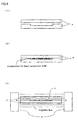
Fig. 4 shows an example of utilization of a rubber sheet shape heat conductive mold of a first embodiment of the present invention (disposed in a gap between a plurality ofheating semiconductor devices 6 and a case 7); -
Fig. 5 shows an example of one manufacturing method of the heat conductive mold of the present invention; -
Fig. 6 shows another example of one manufacturing method of the heat conductive mold of the present invention; -
Fig. 1 ∼ Fig. 4 show examples wherein the heatconductive mold 3 obtained by the present invention is interposed betweenheating semiconductor devices print circuit board 1,heat sink 5, orcase 7. InFigs. 5 and6 ,numeral 8 denotes a mold, and numeral 9 denotes a magnet. - Now, the present invention will be described in more detail based on examples. In the following examples and comparison examples, the heat conductivity was evaluated through the measurement of heat resistance value using a transistor (made by Toshiba Corp. TO-220).
- A composition is prepared by blending 100 weight parts of added type liquid silicon rubber (made by GE Toshiba Silicon, TSE3070), 80 weight parts of hexagonal crystalline system flake form boron nitride powder (Denki Kagaku Kogyo K.K., SGP average particle diameter 19µm) and 100 weight parts of hexane as solvent. The composition is charged into a plate shape die of 15mm in thickness, 20mm in length and 20 mm in width, boron nitride powder is oriented sufficiently under the magnetic field atmosphere where N pole and S pole of 2 tesla in flux density are opposed in the thickness direction, then heat dried to remove solvent hexane, and heat set, to obtain rubber sheet shape heat conductive mold of 1.5mm in thickness. The heat resistance value of the obtained heat conductive mold was 0.26°C/W.
- A composition is prepared by blending 100 weight parts of added type liquid silicon rubber (made by GE Toshiba Silicon, TSE3070), and 80 weight parts of hexagonal crystalline system flake form boron nitride powder (Denki Kagaku Kogyo K.K., S G P
average particle diameter 1 9 µm). The composition is charged into a plate shape die of 15mm in thickness, 20mm in length and 20 mm in width and heat set, to obtain rubber sheet shape heat conductive mold. The heat resistance value of the obtained heat conductive mold was 0.38°C/W. - A composition is prepared by blending 100 weight parts of liquid epoxy resin (made by Three Bond Co., Ltd. TB2280C) and 180 weight parts of hexagonal crystalline system granular boron nitride powder (Showa Denko Co., Ltd. UHP-EX average particle diameter 35 µm). The composition is charged into a plate shape die of 15mm in thickness, 20mm in length and 20 mm in width, boron nitride powder is oriented sufficiently under the magnetic field atmosphere where N pole and S pole of 6 tesla in flux density are opposed in the thickness direction, and heat set, to obtain a hard plate shape heat conductive mold as shown in
Fig. 5(1), Fig. 5(2) and Fig. 5 (3). The heat resistance value of the obtained heat conductive mold was 0.21 °C/W. - A composition is prepared by blending 100 weight parts of liquid epoxy resin (made by Three Bond Co., Ltd. TB2280C) and 180 weight parts of hexagonal crystalline system granular boron nitride powder (Showa Denko Co., Ltd. UHP-EX average particle diameter 35 µm). The composition is charged into a plate shape die of 15mm in thickness, 20mm in length and 20 mm in width, and heat set, to obtain a hard plate shape heat conductive mold. The heat resistance value of the obtained heat conductive mold was 0.32°C/W.
- A composition is prepared by blending 100 weight parts of solid portion of polyimide varnish containing N methyl pyrrolidone as solvent (made by Ube Kosan Co., Ltd., Yupifine ST, concentration of solid portion 18.5%) and 60 weight parts of hexagonal crystalline system flake form boron nitride powder (made by Showa Denko Co., Ltd. UHP-S1
average particle diameter 1 to 2 µ m). The composition is charged into a box die of 20mm in length, 20 mm in width and 40 mm in depth, boron nitride powder is oriented sufficiently under the magnetic field atmosphere where N pole and S pole of 6 tesla in flux density are opposed in the thickness direction, and heat set after having removed solvent N methyl pyrrolidone, to obtain a film shape heat conductive mold of 120µm in thickness. The heat resistance value of the obtained heat conductive mold was 0.18°C/W. - A composition is prepared by blending 100 weight parts of solid portion of polyimide varnish containing N methyl pyrrolidone as solvent (made by Ube Kosan Co., Ltd., Yupifine ST, concentration of solid portion 18.5%) and 60 weight parts of hexagonal crystalline system flake form boron nitride powder
- (made by Showa Denko Co., Ltd. UHP-S1
average particle diameter 1 to 2 µ m). The composition is charged into a box die of 20mm in length, 20 mm in width and 40 mm in depth, and heat set after having removed solvent N methyl pyrrolidone, to obtain a film shape heat conductive mold of 120 µm in thickness. The heat resistance value of the obtained heat conductive mold was 0.27°C/W. - Comparison Example 1 Comparison Example 3 are conventional molds wherein flake form boron nitride powder is charged into polymer, and Comparison Example 2 is one wherein granular boron nitride powder is charged, and they present a high heat resistance value. The heat conductive mold of Example 1, Example 2, Example 3 of the present invention are obtained by impressing magnetic field to the polymer composition containing the same amount of flake form boron nitride powder or granular boron nitride powder as the corresponding Comparison Example, field orienting boron nitride powder in the composition, and then heat setting, and each presents smaller heat resistance value and better heat conductivity than the corresponding Comparison Example.
- As described above, the present invention allows to produce a heat conductive mold of excellent heat conductivity, by impressing magnetic field to the polymer composition containing in particular flake form boron nitride powder or granular boron nitride powder, field orienting boron nitride powder in the composition to a fixed direction, and then heat setting.
- Using the heat conductive mold of the present invention, various radiation components requiring a high heat conductivity such as high heat value CPU (central processing unit) or other semiconductors, power source, light source, plasma display, printed circuit board or the like can be supplied.
Claims (6)
- A method of manufacturing a heat conductive mold, by impressing magnetic field to a polymer composition containing boron nitride powder having flake form, flat form, granular form, aggregated form, fiber form or whisker form, field orientating the boron nitride powder in the composition to a direction aligned with a direction of magnetic line of force, and then setting the same,
wherein the field orientating process includes orientating the boron nitride powder to increase the heat conductivity of the mold in said direction by using the magnetic anisotropy characteristic of the boron nitride powder, and
wherein the content of boron nitride powder is 20 to 400 weight parts to 100 weight parts of polymer. - A method of manufacturing a heat conductive mold as claimed in claim 1, wherein the polymer is at least one selected from silicon rubber, epoxy, polyimide and polyurethane.
- A method as claimed in claim 1 or 2, further comprising impressing magnetic field to a polymer composition containing boron nitride powder and solvent, and then setting the same after having removed the solvent.
- A method as claimed in any of claims 1 to 3, wherein individual average primary diameter of the boron nitride powder is in the range of 0.01 to 100 µm.
- A method as claimed in claim 1, wherein a direction of magnetic line of force is arranged in a sheet thickness direction (direction vertical to a sheet surface) with respect to a sheet-shaped polymer composition containing boron nitride powder.
- A method as claimed in claim 1, wherein a direction of magnetic line of force is arranged in a fixed direction along a sheet surface with respect to a sheet-shaped polymer composition containing boron nitride powder.
Applications Claiming Priority (2)
| Application Number | Priority Date | Filing Date | Title |
|---|---|---|---|
| JP35864699 | 1999-12-17 | ||
| JP35864699A JP2001172398A (en) | 1999-12-17 | 1999-12-17 | Thermal conduction molded product and its production method |
Publications (3)
| Publication Number | Publication Date |
|---|---|
| EP1109218A2 EP1109218A2 (en) | 2001-06-20 |
| EP1109218A3 EP1109218A3 (en) | 2003-04-02 |
| EP1109218B1 true EP1109218B1 (en) | 2010-12-01 |
Family
ID=18460395
Family Applications (1)
| Application Number | Title | Priority Date | Filing Date |
|---|---|---|---|
| EP00310713A Expired - Lifetime EP1109218B1 (en) | 1999-12-17 | 2000-12-01 | Heat conducting mold and manufacturing method thereof |
Country Status (4)
| Country | Link |
|---|---|
| US (2) | US20010004546A1 (en) |
| EP (1) | EP1109218B1 (en) |
| JP (1) | JP2001172398A (en) |
| DE (1) | DE60045301D1 (en) |
Cited By (3)
| Publication number | Priority date | Publication date | Assignee | Title |
|---|---|---|---|---|
| US8561934B2 (en) | 2009-08-28 | 2013-10-22 | Teresa M. Kruckenberg | Lightning strike protection |
| US8752279B2 (en) | 2007-01-04 | 2014-06-17 | Goodrich Corporation | Methods of protecting an aircraft component from ice formation |
| US8962130B2 (en) | 2006-03-10 | 2015-02-24 | Rohr, Inc. | Low density lightning strike protection for use in airplanes |
Families Citing this family (49)
| Publication number | Priority date | Publication date | Assignee | Title |
|---|---|---|---|---|
| JP2002069392A (en) * | 2000-08-31 | 2002-03-08 | Polymatech Co Ltd | Heat-conductive adhesive film, method for producing the same and electronic part |
| JP2003060134A (en) * | 2001-08-17 | 2003-02-28 | Polymatech Co Ltd | Heat conductive sheet |
| US6921462B2 (en) | 2001-12-17 | 2005-07-26 | Intel Corporation | Method and apparatus for producing aligned carbon nanotube thermal interface structure |
| US6965513B2 (en) | 2001-12-20 | 2005-11-15 | Intel Corporation | Carbon nanotube thermal interface structures |
| US6856016B2 (en) | 2002-07-02 | 2005-02-15 | Intel Corp | Method and apparatus using nanotubes for cooling and grounding die |
| TWI239606B (en) * | 2002-11-07 | 2005-09-11 | Kobe Steel Ltd | Heat spreader and semiconductor device and package using the same |
| US7316061B2 (en) | 2003-02-03 | 2008-01-08 | Intel Corporation | Packaging of integrated circuits with carbon nano-tube arrays to enhance heat dissipation through a thermal interface |
| US7168484B2 (en) | 2003-06-30 | 2007-01-30 | Intel Corporation | Thermal interface apparatus, systems, and methods |
| US7031162B2 (en) * | 2003-09-26 | 2006-04-18 | International Business Machines Corporation | Method and structure for cooling a dual chip module with one high power chip |
| KR100581863B1 (en) * | 2003-10-09 | 2006-05-22 | 삼성에스디아이 주식회사 | Plasma display device |
| US20050083641A1 (en) * | 2003-10-21 | 2005-04-21 | Shu-Ju Lin | Central processing unit |
| US7456052B2 (en) | 2003-12-30 | 2008-11-25 | Intel Corporation | Thermal intermediate apparatus, systems, and methods |
| US7180174B2 (en) | 2003-12-30 | 2007-02-20 | Intel Corporation | Nanotube modified solder thermal intermediate structure, systems, and methods |
| JP2005331945A (en) * | 2004-05-18 | 2005-12-02 | Samsung Sdi Co Ltd | Plasma display display |
| JP2006273948A (en) * | 2005-03-28 | 2006-10-12 | Mitsui Chemicals Inc | Thermally-conductive resin composition and use of the same |
| JP4747926B2 (en) * | 2005-05-25 | 2011-08-17 | 東ソー株式会社 | Polyarylene sulfide composition |
| BRPI0614969A2 (en) * | 2005-08-26 | 2016-09-13 | Cool Options Inc | composition and method for microelectronic matrix level conditioning |
| KR100646404B1 (en) * | 2005-10-26 | 2006-11-14 | 주식회사 만도 | Electronic control unit and electric power steering apparatus including same |
| JP4747918B2 (en) | 2005-11-04 | 2011-08-17 | 東ソー株式会社 | Polyarylene sulfide composition |
| JP2007286785A (en) * | 2006-04-14 | 2007-11-01 | Fujitsu Ltd | Electronic device and cooling part |
| JP4747931B2 (en) * | 2006-04-25 | 2011-08-17 | 東ソー株式会社 | Polyarylene sulfide composition |
| JP2007291300A (en) * | 2006-04-27 | 2007-11-08 | Tosoh Corp | Polyarylene sulfide composition |
| CN101484628A (en) | 2006-05-02 | 2009-07-15 | 罗尔股份有限公司 | Modification of reinforcing fiber tows used in composite materials by using nanoreinforcements |
| CN101535176A (en) * | 2006-10-07 | 2009-09-16 | 迈图高新材料公司 | Mixed boron nitride composition and method for making thereof |
| JP5608371B2 (en) * | 2007-01-10 | 2014-10-15 | モメンティブ パフォーマンス マテリアルズ インコーポレイテッド | Thermal interface material and manufacturing method thereof |
| JP5042899B2 (en) * | 2008-03-31 | 2012-10-03 | ポリマテック株式会社 | Thermally conductive sheet and method for producing the same |
| US7906376B2 (en) * | 2008-06-30 | 2011-03-15 | Intel Corporation | Magnetic particle-based composite materials for semiconductor packages |
| JP5308859B2 (en) * | 2008-10-20 | 2013-10-09 | 株式会社カネカ | Highly light-resistant and heat-conductive resin molded product for lighting equipment |
| US8277936B2 (en) * | 2008-12-22 | 2012-10-02 | E I Du Pont De Nemours And Company | Hexagonal boron nitride compositions characterized by interstitial ferromagnetic layers, process for preparing, and composites thereof with organic polymers |
| US8784980B2 (en) * | 2009-05-13 | 2014-07-22 | E I Du Pont De Nemours And Company | Film prepared from a casting composition comprising a polymer and surface modified hexagonal boron nitride particles |
| JP5646823B2 (en) * | 2009-05-27 | 2014-12-24 | 株式会社カネカ | High thermal conductivity polyimide film |
| JP5513840B2 (en) * | 2009-10-22 | 2014-06-04 | 電気化学工業株式会社 | Insulating sheet, circuit board, and insulating sheet manufacturing method |
| JP5759192B2 (en) * | 2010-01-29 | 2015-08-05 | 日東電工株式会社 | Backlight and liquid crystal display device |
| DE102010050900A1 (en) | 2010-11-10 | 2012-05-10 | Esk Ceramics Gmbh & Co. Kg | Boron nitride agglomerates, process for their preparation and their use |
| WO2014047274A1 (en) * | 2012-09-19 | 2014-03-27 | Momentive Performance Materials Inc. | Masterbatch comprising boron nitride, composite powders thereof, and compositions and articles comprising such materials |
| CN102924923B (en) * | 2012-10-24 | 2014-12-03 | 江苏大学 | High thermal conductive magnetic metal fiber/silicon rubber composite material and preparation method thereof |
| JP6438701B2 (en) * | 2014-08-18 | 2018-12-19 | パナソニック株式会社 | Heat dissipation rubber composition |
| US10022896B2 (en) * | 2015-11-23 | 2018-07-17 | The Boeing Company | Controlling the heating of a composite part |
| TWI588251B (en) | 2015-12-08 | 2017-06-21 | 財團法人工業技術研究院 | Magnetic and thermally conductive material and thermally conductive and dielectric layer |
| JP7120229B2 (en) * | 2017-06-09 | 2022-08-17 | 三菱瓦斯化学株式会社 | Method for manufacturing anisotropic filler-containing sheet |
| EP3460839A1 (en) * | 2017-09-21 | 2019-03-27 | GWP Gesellschaft Für Werkstoffprüfung MbH | Films for use in semiconductor technology |
| US20210074472A1 (en) * | 2018-03-09 | 2021-03-11 | Marvis White | Thermally conductive composite dielectric materials |
| US20210062061A1 (en) * | 2018-05-10 | 2021-03-04 | Georgia Tech Research Corporation | Thermal Management Materials and Methods of Making the Same |
| US10923412B2 (en) * | 2018-08-10 | 2021-02-16 | Cerebras Systems Inc. | Apparatuses and methods for implementing a sliding thermal interface between substrates with varying coefficients of thermal expansion |
| US10811187B2 (en) * | 2018-09-18 | 2020-10-20 | Toyota Motor Engineering & Manufacturing North America, Inc. | Methods of fabricating thermal composites having specifically designed particle distributions |
| JP2020055961A (en) * | 2018-10-03 | 2020-04-09 | 信越化学工業株式会社 | Resin sheet having controlled heat conductivity distribution, and method of manufacturing the same |
| US11862603B2 (en) * | 2019-11-27 | 2024-01-02 | Samsung Electronics Co., Ltd. | Semiconductor packages with chips partially embedded in adhesive |
| CN111484627A (en) * | 2020-04-26 | 2020-08-04 | 赵汉波 | Functional boron nitride in-situ modified epoxy resin insulating material and preparation method thereof |
| CN113150557A (en) * | 2021-04-08 | 2021-07-23 | 华南理工大学 | Silicon rubber composite material with directional arrangement and three-dimensional structure construction for improving heat conductivity, and preparation method and application thereof |
Family Cites Families (17)
| Publication number | Priority date | Publication date | Assignee | Title |
|---|---|---|---|---|
| JPS5029939B2 (en) * | 1972-07-05 | 1975-09-27 | ||
| ZA741474B (en) * | 1974-03-07 | 1975-10-29 | Edenvale Eng Works | Abrasive tools |
| US4256792A (en) * | 1980-01-25 | 1981-03-17 | Honeywell Inc. | Composite electronic substrate of alumina uniformly needled through with aluminum nitride |
| JPS58152033A (en) * | 1982-03-04 | 1983-09-09 | Japan Synthetic Rubber Co Ltd | Anisotropic electrically conductive rubber sheet |
| JPS6169866A (en) * | 1984-09-12 | 1986-04-10 | Polyplastics Co | Composite material composition |
| JPH0612643B2 (en) * | 1985-12-25 | 1994-02-16 | 信越化学工業株式会社 | Thermally conductive insulation sheet |
| JPH0638460B2 (en) * | 1989-11-08 | 1994-05-18 | 東海ゴム工業株式会社 | Heat dissipation sheet |
| US5660917A (en) * | 1993-07-06 | 1997-08-26 | Kabushiki Kaisha Toshiba | Thermal conductivity sheet |
| JPH0788971A (en) * | 1993-09-21 | 1995-04-04 | Tokai Rubber Ind Ltd | Semiconductive sheet |
| JP3698451B2 (en) * | 1995-03-13 | 2005-09-21 | 電気化学工業株式会社 | Sheet manufacturing method |
| JPH1160216A (en) * | 1997-08-04 | 1999-03-02 | Shin Etsu Chem Co Ltd | Heat conductive boron nitride filler and insulating heat releasing sheet |
| JP3434678B2 (en) * | 1997-09-12 | 2003-08-11 | 電気化学工業株式会社 | Rubber sheet manufacturing method |
| JP3372462B2 (en) * | 1997-11-27 | 2003-02-04 | 電気化学工業株式会社 | Rubber sheet manufacturing method |
| JP3283226B2 (en) * | 1997-12-26 | 2002-05-20 | ポリマテック株式会社 | How to make a holder |
| JP2000281802A (en) * | 1999-03-30 | 2000-10-10 | Polymatech Co Ltd | Thermoconductive formed shape, its production, and semiconductor device |
| JP4528397B2 (en) * | 1999-12-17 | 2010-08-18 | ポリマテック株式会社 | Bonding method and electronic component |
| JP2002069392A (en) * | 2000-08-31 | 2002-03-08 | Polymatech Co Ltd | Heat-conductive adhesive film, method for producing the same and electronic part |
-
1999
- 1999-12-17 JP JP35864699A patent/JP2001172398A/en active Pending
-
2000
- 2000-12-01 DE DE60045301T patent/DE60045301D1/en not_active Expired - Lifetime
- 2000-12-01 EP EP00310713A patent/EP1109218B1/en not_active Expired - Lifetime
- 2000-12-08 US US09/733,559 patent/US20010004546A1/en not_active Abandoned
-
2003
- 2003-02-18 US US10/370,301 patent/US6761842B2/en not_active Expired - Fee Related
Cited By (3)
| Publication number | Priority date | Publication date | Assignee | Title |
|---|---|---|---|---|
| US8962130B2 (en) | 2006-03-10 | 2015-02-24 | Rohr, Inc. | Low density lightning strike protection for use in airplanes |
| US8752279B2 (en) | 2007-01-04 | 2014-06-17 | Goodrich Corporation | Methods of protecting an aircraft component from ice formation |
| US8561934B2 (en) | 2009-08-28 | 2013-10-22 | Teresa M. Kruckenberg | Lightning strike protection |
Also Published As
| Publication number | Publication date |
|---|---|
| EP1109218A3 (en) | 2003-04-02 |
| US20030153665A1 (en) | 2003-08-14 |
| US20010004546A1 (en) | 2001-06-21 |
| DE60045301D1 (en) | 2011-01-13 |
| JP2001172398A (en) | 2001-06-26 |
| EP1109218A2 (en) | 2001-06-20 |
| US6761842B2 (en) | 2004-07-13 |
Similar Documents
| Publication | Publication Date | Title |
|---|---|---|
| EP1109218B1 (en) | Heat conducting mold and manufacturing method thereof | |
| US6660566B2 (en) | Heat conductive molded body and manufacturing method thereof and semiconductor device | |
| JP2002080617A (en) | Thermoconductive sheet | |
| US6918983B2 (en) | Adhesion method and electronic component | |
| US6663969B2 (en) | Heat conductive adhesive film and manufacturing method thereof and electronic component | |
| US7264869B2 (en) | Thermally conductive molded article and method of making the same | |
| US20030040563A1 (en) | Substantially non-abrasive thermally conductive polymer composition containing boron nitride | |
| JP2003321554A (en) | Heat-conductive molding and method for producing the same | |
| CN109891577B (en) | Thermally conductive sheet and semiconductor device | |
| CN1893803A (en) | Heat radiation member and production method for the same | |
| JP2000195998A (en) | Heat conductive sheet, its manufacture, and semiconductor device | |
| JP2000281995A (en) | Thermally conductive adhesive film and semiconductor device | |
| JP7384560B2 (en) | Thermal conductive sheets, mounting methods for thermal conductive sheets, manufacturing methods for electronic devices | |
| JP2000191987A (en) | Thermally conductive adhesive film and semiconductive device | |
| JP5365861B2 (en) | Heat transfer sheet and manufacturing method thereof | |
| JP2000273426A (en) | Thermal conductive adhesive, bonding and semiconductor device | |
| JP4272767B2 (en) | Thermally conductive molded body and method for producing the same, resin substrate for conductor circuit and method for producing the same | |
| US20240120254A1 (en) | Thermally-conductive sheet and electronic device | |
| KR20140094294A (en) | Heat discharging sheet of electrically insulative | |
| JP3640524B2 (en) | Heat dissipation spacer | |
| KR20140085053A (en) | Heat-transferring adhesive tape composition and heat-transferring adhesive tape and method of manufacturing the same | |
| JP2007084705A (en) | Resin composition and circuit board and package using the same | |
| TWI382083B (en) | Method for manufacturing thermal interface material |
Legal Events
| Date | Code | Title | Description |
|---|---|---|---|
| PUAI | Public reference made under article 153(3) epc to a published international application that has entered the european phase |
Free format text: ORIGINAL CODE: 0009012 |
|
| AK | Designated contracting states |
Kind code of ref document: A2 Designated state(s): AT BE CH CY DE DK ES FI FR GB GR IE IT LI LU MC NL PT SE TR |
|
| AX | Request for extension of the european patent |
Free format text: AL;LT;LV;MK;RO;SI |
|
| 17P | Request for examination filed |
Effective date: 20011113 |
|
| PUAL | Search report despatched |
Free format text: ORIGINAL CODE: 0009013 |
|
| AK | Designated contracting states |
Kind code of ref document: A3 Designated state(s): AT BE CH CY DE DK ES FI FR GB GR IE IT LI LU MC NL PT SE TR Designated state(s): AT BE CH CY DE DK ES FI FR GB GR IE IT LI LU MC NL PT SE TR |
|
| AX | Request for extension of the european patent |
Extension state: AL LT LV MK RO SI |
|
| RIC1 | Information provided on ipc code assigned before grant |
Ipc: 7H 01L 21/48 B Ipc: 7H 01L 23/433 B Ipc: 7H 01L 23/373 A |
|
| AKX | Designation fees paid |
Designated state(s): DE GB NL |
|
| 17Q | First examination report despatched |
Effective date: 20050309 |
|
| GRAP | Despatch of communication of intention to grant a patent |
Free format text: ORIGINAL CODE: EPIDOSNIGR1 |
|
| RIN1 | Information on inventor provided before grant (corrected) |
Inventor name: KIMURA, TSUNEHISAEXCEL HEIGHTS 301, Inventor name: YAMATO, MASAHUMI, Inventor name: TATEDA, SHINYA,R&D CENTER OF POLYMATCH CO., LTD Inventor name: TOBITA, MASAYUKI,R&D CENTER OF POLYMATCH CO., LTD |
|
| GRAS | Grant fee paid |
Free format text: ORIGINAL CODE: EPIDOSNIGR3 |
|
| GRAA | (expected) grant |
Free format text: ORIGINAL CODE: 0009210 |
|
| AK | Designated contracting states |
Kind code of ref document: B1 Designated state(s): DE GB NL |
|
| REG | Reference to a national code |
Ref country code: GB Ref legal event code: FG4D |
|
| REF | Corresponds to: |
Ref document number: 60045301 Country of ref document: DE Date of ref document: 20110113 Kind code of ref document: P |
|
| REG | Reference to a national code |
Ref country code: NL Ref legal event code: VDEP Effective date: 20101201 |
|
| PG25 | Lapsed in a contracting state [announced via postgrant information from national office to epo] |
Ref country code: NL Free format text: LAPSE BECAUSE OF FAILURE TO SUBMIT A TRANSLATION OF THE DESCRIPTION OR TO PAY THE FEE WITHIN THE PRESCRIBED TIME-LIMIT Effective date: 20101201 |
|
| PGFP | Annual fee paid to national office [announced via postgrant information from national office to epo] |
Ref country code: DE Payment date: 20110202 Year of fee payment: 11 |
|
| PGFP | Annual fee paid to national office [announced via postgrant information from national office to epo] |
Ref country code: GB Payment date: 20110202 Year of fee payment: 11 |
|
| PLBE | No opposition filed within time limit |
Free format text: ORIGINAL CODE: 0009261 |
|
| STAA | Information on the status of an ep patent application or granted ep patent |
Free format text: STATUS: NO OPPOSITION FILED WITHIN TIME LIMIT |
|
| 26N | No opposition filed |
Effective date: 20110902 |
|
| REG | Reference to a national code |
Ref country code: DE Ref legal event code: R097 Ref document number: 60045301 Country of ref document: DE Effective date: 20110902 |
|
| GBPC | Gb: european patent ceased through non-payment of renewal fee |
Effective date: 20111201 |
|
| REG | Reference to a national code |
Ref country code: DE Ref legal event code: R119 Ref document number: 60045301 Country of ref document: DE Effective date: 20120703 |
|
| PG25 | Lapsed in a contracting state [announced via postgrant information from national office to epo] |
Ref country code: DE Free format text: LAPSE BECAUSE OF NON-PAYMENT OF DUE FEES Effective date: 20120703 Ref country code: GB Free format text: LAPSE BECAUSE OF NON-PAYMENT OF DUE FEES Effective date: 20111201 |