EP1108540A1 - Appareil et procédé pour changer la taille des gouttes pour l'impression jet d'encre - Google Patents
Appareil et procédé pour changer la taille des gouttes pour l'impression jet d'encre Download PDFInfo
- Publication number
- EP1108540A1 EP1108540A1 EP00127697A EP00127697A EP1108540A1 EP 1108540 A1 EP1108540 A1 EP 1108540A1 EP 00127697 A EP00127697 A EP 00127697A EP 00127697 A EP00127697 A EP 00127697A EP 1108540 A1 EP1108540 A1 EP 1108540A1
- Authority
- EP
- European Patent Office
- Prior art keywords
- driving waveform
- transducer
- drops
- ink jet
- control signal
- Prior art date
- Legal status (The legal status is an assumption and is not a legal conclusion. Google has not performed a legal analysis and makes no representation as to the accuracy of the status listed.)
- Granted
Links
Images


Classifications
-
- B—PERFORMING OPERATIONS; TRANSPORTING
- B41—PRINTING; LINING MACHINES; TYPEWRITERS; STAMPS
- B41J—TYPEWRITERS; SELECTIVE PRINTING MECHANISMS, i.e. MECHANISMS PRINTING OTHERWISE THAN FROM A FORME; CORRECTION OF TYPOGRAPHICAL ERRORS
- B41J2/00—Typewriters or selective printing mechanisms characterised by the printing or marking process for which they are designed
- B41J2/005—Typewriters or selective printing mechanisms characterised by the printing or marking process for which they are designed characterised by bringing liquid or particles selectively into contact with a printing material
- B41J2/01—Ink jet
- B41J2/015—Ink jet characterised by the jet generation process
- B41J2/04—Ink jet characterised by the jet generation process generating single droplets or particles on demand
- B41J2/045—Ink jet characterised by the jet generation process generating single droplets or particles on demand by pressure, e.g. electromechanical transducers
- B41J2/04501—Control methods or devices therefor, e.g. driver circuits, control circuits
- B41J2/04581—Control methods or devices therefor, e.g. driver circuits, control circuits controlling heads based on piezoelectric elements
-
- B—PERFORMING OPERATIONS; TRANSPORTING
- B41—PRINTING; LINING MACHINES; TYPEWRITERS; STAMPS
- B41J—TYPEWRITERS; SELECTIVE PRINTING MECHANISMS, i.e. MECHANISMS PRINTING OTHERWISE THAN FROM A FORME; CORRECTION OF TYPOGRAPHICAL ERRORS
- B41J2/00—Typewriters or selective printing mechanisms characterised by the printing or marking process for which they are designed
- B41J2/005—Typewriters or selective printing mechanisms characterised by the printing or marking process for which they are designed characterised by bringing liquid or particles selectively into contact with a printing material
- B41J2/01—Ink jet
- B41J2/015—Ink jet characterised by the jet generation process
- B41J2/04—Ink jet characterised by the jet generation process generating single droplets or particles on demand
- B41J2/045—Ink jet characterised by the jet generation process generating single droplets or particles on demand by pressure, e.g. electromechanical transducers
- B41J2/04501—Control methods or devices therefor, e.g. driver circuits, control circuits
- B41J2/04588—Control methods or devices therefor, e.g. driver circuits, control circuits using a specific waveform
-
- B—PERFORMING OPERATIONS; TRANSPORTING
- B41—PRINTING; LINING MACHINES; TYPEWRITERS; STAMPS
- B41J—TYPEWRITERS; SELECTIVE PRINTING MECHANISMS, i.e. MECHANISMS PRINTING OTHERWISE THAN FROM A FORME; CORRECTION OF TYPOGRAPHICAL ERRORS
- B41J2/00—Typewriters or selective printing mechanisms characterised by the printing or marking process for which they are designed
- B41J2/005—Typewriters or selective printing mechanisms characterised by the printing or marking process for which they are designed characterised by bringing liquid or particles selectively into contact with a printing material
- B41J2/01—Ink jet
- B41J2/015—Ink jet characterised by the jet generation process
- B41J2/04—Ink jet characterised by the jet generation process generating single droplets or particles on demand
- B41J2/045—Ink jet characterised by the jet generation process generating single droplets or particles on demand by pressure, e.g. electromechanical transducers
- B41J2/04501—Control methods or devices therefor, e.g. driver circuits, control circuits
- B41J2/04593—Dot-size modulation by changing the size of the drop
-
- B—PERFORMING OPERATIONS; TRANSPORTING
- B41—PRINTING; LINING MACHINES; TYPEWRITERS; STAMPS
- B41J—TYPEWRITERS; SELECTIVE PRINTING MECHANISMS, i.e. MECHANISMS PRINTING OTHERWISE THAN FROM A FORME; CORRECTION OF TYPOGRAPHICAL ERRORS
- B41J2/00—Typewriters or selective printing mechanisms characterised by the printing or marking process for which they are designed
- B41J2/005—Typewriters or selective printing mechanisms characterised by the printing or marking process for which they are designed characterised by bringing liquid or particles selectively into contact with a printing material
- B41J2/01—Ink jet
- B41J2/21—Ink jet for multi-colour printing
- B41J2/2121—Ink jet for multi-colour printing characterised by dot size, e.g. combinations of printed dots of different diameter
- B41J2/2128—Ink jet for multi-colour printing characterised by dot size, e.g. combinations of printed dots of different diameter by means of energy modulation
Definitions
- This invention relates generally to an apparatus and method for improving resolution in gray scale printing and, more specifically, to an apparatus and method for modulated drop volume ink jet printing that utilizes a single driving waveform to produce on-demand multiple ink drop sizes from a single orifice. More specifically, knowing an input request, a combination of small drops and large drops are placed in a conventional blue noise halftone screen represented as a threshold array according to a unique drop deposition algorithm such that throughput and image quality goals are met while decreasing jetting robustness risk.
- Prior drop-on-demand ink jet print heads typically eject ink drops of a single volume that produce on a print medium dots of ink sized to provide printing at a given resolution, such as 12 dots per millimeter (300 dots per inch (dpi)).
- Single dot size printing is acceptable for most text and graphics printing applications that do not require high image quality.
- Higher image quality, such as "photographic" image quality normally requires higher resolution, which slows the print speed.
- Image quality may also be improved by adding ink color densities, which undesirably requires an increase in the number of jets in the print head.
- Another technique for improving image quality is to modulate the reflectance, or gray scale, of the dots forming the image.
- the average reflectance of an image portion is typically modulated by a process referred to as "dithering."
- the perceived intensity of an array of dots is modulated by selectively printing the array at a predetermined dot density. For example, if a 50 percent local average reflectance is desired, half of the dots in the array are printed.
- a "checker-board" pattern provides the most uniform appearing 50 percent local average reflectance. Multiple dither pattern dot densities are possible to provide a wide range of reflectance levels.
- Ink dot size modulation also referred to as drop volume and drop mass modulation.
- Ink drop volume modulation entails controlling the volume of each drop of ink ejected by the ink jet print head.
- Drop volume modulation advantageously provides greater effective printing resolution without sacrificing print speed. For example, an image printed with two dot sizes at 12 dots per millimeter (300 dots per inch) resolution may have a better appearance than the same image printed with one dot size at 24 dots per millimeter (600 dots per inch) resolution. This increase in effective resolution is possible because using two or more dot sizes in low optical density areas increases the dot density (dots/area), which in turn decreases graininess.
- varying the drop volume may also vary the drop ejection velocity and result in drop landing position errors. Constant drop volume, therefore, is taught as a way of maintaining image quality.
- the drop ejection rate is also limited to about 3000 drops per second (3 kHz), a rate that is slow compared to typical printing speed requirements.
- U.S. Pat. No. 5,124,716 for a METHOD AND APPARATUS FOR PRINTING WITH INK DROPS OF VARYING SIZES USING A DROP-ON-DEMAND INK JET PRINT HEAD assigned to the assignee of the present invention
- U.S. Pat. No. 4,639,735 for APPARATUS FOR DRIVING LIQUID JET HEAD describe circuits and PZT drive waveforms suitable for ejecting ink drops smaller than an ink jet orifice diameter.
- a separate drive waveform must be generated and applied to the PZT for each different drop size.
- the waveform generating componentry required to produce the multiple waveforms is undesirably complex and adds additional cost to the printer.
- U.S. Patent No. 5,689,291 for a METHOD AND APPARATUS FOR PRODUCING DOT SIZE MODULATED INK JET PRINTING assigned to the assignee of the present application, provides multiple PZT drive waveforms for producing various ink drop volumes.
- the various ejected ink drop volumes have substantially the same ejection velocity over a range of drop ejection repetition rates.
- a different drive waveform must be generated and applied to the PZT for each drop volume desired.
- a control signal is utilized to manipulate the driving waveform to eject the desired ink drop volume for a given pixel.
- the apparatus and method perform on-demand selection of two or more drop volumes for a given pixel without sacrificing print speed.
- an apparatus and method provide on-demand drop volume modulation by utilizing a single transducer drive waveform.
- the drive waveform includes at least a first portion and a second portion that each excites a different modal resonance of ink in an ink jet orifice to produce ink drops having different volumes.
- the apparatus and method improves resolution in gray scale printing by knowing an input request and placing a combination of small drops and large drops in a conventional blue noise halftone screen represented as a threshold array according to a unique drop deposition algorithm such that throughput and image quality goals are met while decreasing jetting robustness risk.
- the waveform generator generates the driving waveform at a frequency that ejects fluid drops from the orifice at a maximum ejection rate of between about 15,000 fluid drops per second to about 18,000 fluid drops per second.
- the control signal comprises a pulse corresponding to a first portion of the driving waveform producing one or more large drops and the second portion of the driving waveform producing one or more small drops wherein the large drops and small drops continue to fill the threshold array according to a blue noise halftone screen based on the slope of output percent digital coverage over input percent digital coverage for a given input request until no vacancies remain.
- Fig. 1 shows a schematic view of an individual ink jet 10 according to the present invention.
- the ink jet 10 is a part of a multiple-orifice ink jet print head suitable for use with this invention.
- Ink jet 10 includes an ink manifold 12 that receives ink from a reservoir (not shown). Ink flows from manifold 12 through an inlet channel 18 into an ink pressure chamber 22. Ink flows from the pressure chamber 22 into an outlet channel 28 to the ink drop forming orifice 14, from which an ink drop 16 is ejected toward a receiving surface 20.
- a typical ink jet print head includes an array of orifices that are closely spaced from one another for use in ejecting drops of ink toward a receiving surface.
- the typical print head also has at least four manifolds for receiving black, cyan, magenta and yellow ink for use in monochrome plus subtractive color printing.
- the number of such manifolds may be varied where a printer is designed to print solely in black ink, gray scale or with less than a full range of color.
- ink pressure chamber 22 is bounded on one side by a flexible diaphragm 34.
- An electro mechanical transducer 32 such as a piezoelectric transducer (PZT) is secured to diaphragm 34 by an appropriate adhesive and overlays ink pressure chamber 22.
- the transducer mechanism 32 can comprise a ceramic transducer bonded with epoxy to the diaphragm plate 34, with the transducer centered over the ink pressure chamber 22.
- the transducer may be substantially rectangular in shape, or alternatively, may be substantially circular or disc-shaped.
- transducer 32 has metal film layers 36 to which an electronic transducer driver 40 is electrically connected.
- the preferred transducer 32 is a bending-mode transducer. It will be appreciated that other types and forms of transducers may also be used, such as shear-mode, annular constrictive, electrostrictive, electromagnetic or magnetostrictive transducers.
- Transducer 32 is operated in its bending mode such that when a voltage is applied across metal film layers 34, transducer 32 attempts to change its dimensions. Because it is securely and rigidly attached to diaphragm 34, transducer 32 bends and deforms diaphragm 34, thereby displacing ink in ink pressure chamber 22 and causing the outward flow of ink through outlet channel 28 to nozzle 14. Refill of ink pressure chamber 22 following the ejection of an ink drop is accomplished by reverse bending of transducer 32 and the resulting movement of diaphragm 34.
- Ink jet 10 may be formed from multiple laminated plates or sheets, such as sheets of stainless steel, that are stacked in a superimposed relationship.
- An example of a multiple-plate ink jet is disclosed in U.S. Patent No. 5,689,291 entitled METHOD AND APPARATUS FOR PRODUCING DOT SIZE MODULATED INK JET PRINTING, and assigned to the assignee of the present application.
- U.S. Patent No. 5,689,291 is specifically incorporated by reference in pertinent part. It will be appreciated that various numbers and combinations of plates may be utilized to form the ink jet 10 and its individual components and features. Persons skilled in the art will also recognize that other modifications and additional features may be utilized with this type of ink jet to achieve a desired level of performance and/or reliability.
- acoustic filters may be incorporated into the ink jet to dampen extraneous and potentially harmful pressure waves.
- the positioning of the manifolds, pressure chambers and inlet and outlet channels in the print head may also be modified to control ink jet performance.
- a driving waveform is provided to transducer 32 from a transducer driver 40.
- Transducer 32 responds to the driving waveform by inducing pressure waves in the ink that excite ink fluid flow resonances in orifice 14 and at the ink surface meniscus. The particular resonance mode excited by the waveform determines the drop volume ejected.
- Designing drive waveforms suitable for ejecting a desired drop volume generally involves concentrating energy at frequencies near the natural frequency of a desired mode, and suppressing energy at the natural frequencies of other modes. Extraneous and parasitic resonant frequencies that compete for energy with the desired mode should also be controlled. A more detailed discussion of designing drive waveforms is found in the earlier referenced and incorporated U.S. Patent 5,689,291.
- the driving waveform 100 includes a first bi-polar portion 110 and a second bi-polar portion 120 that includes two positive pulses.
- the first portion 110 of the driving waveform 100 includes a plus 35 volt, 16 microsecond pulse component 112 and a negative 26 volt, 9 microsecond pulse component 114 separated by a 1 microsecond wait period 116.
- the second portion 120 of the driving waveform follows the first portion 110 after a 1 microsecond wait period 118.
- a preferred embodiment of the second portion waveform 120 is illustrated.
- the second portion waveform 120 includes a plus 35 volt, 13 microsecond pulse component 122 and a negative 35 volt, 4 microsecond pulse component 124 separated by a 0.5 microsecond wait period 126.
- a second positive voltage pulse comprising a plus 26 volt, 7 microsecond pulse component 130.
- the first and second portions 110, 120 of the driving waveform 100 are each designed to generate ink drops having a different volume.
- the first portion waveform 110 when utilized with an ink jet of the type shown in Fig. 1, the first portion waveform 110 generates an ink drop having a volume of approximately 58 picoliters, and the second portion waveform 120 generates an ink drop having a volume of approximately 27 picoliters.
- a control signal is applied to the driving waveform 100 to enable the desired portion of the driving waveform to actuate the transducer and eject a fluid drop having a desired volume.
- this combination of a single, multiple drop size driving waveform and control signal allows for pixel-by-pixel, on-demand selection of multiple ink drop sizes.
- the print head may eject mulitple ink drop volumes during a single rotation of the receiving surface.
- output containing multiple ink drop sizes may be created on a receiving surface at a constant speed.
- the control signal 150 is a substantially rectangular waveform that includes an actuation component 152 having a positive voltage and a cancellation component 154 having a zero voltage.
- the actuation component 152 is a 5 volt pulse having a duration substantially equal to the driving waveform portion being actuated.
- the cancellation component 154 is a 0 volt flat line having a duration substantially equal to the driving waveform portion not selected.
- Figures 2a and 2b graphically illustrate the actuation of the first portion 110 of the driving waveform 100 and the cancellation of the second portion 120 of the waveform, thereby producing a 58 picoliter ink drop.
- the actuation component 152 of the control signal 150 is applied to correspond to the second portion 120 of the waveform, and the cancellation component 154 corresponds to the first portion 110.
- the control signal enables the desired portion of the driving waveform and cancels the non-selected portion to eject the desired volume ink drop for a given pixel.
- the entire control signal 150 will be a 0 volt flat line that cancels the entire driving waveform 100 when no ink drop is desired for a given pixel.
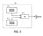
- FIG. 5 schematically illustrates apparatus representative of the transducer driver 40 (see Fig. 1) that is suitable for generating the driving waveform 100 and the control signal 150.
- the transducer driver 40 includes an image loader 42 that generates the control signal 150 and a waveform generator 44 that generates the driving waveform 100. Any suitable commercial waveform generator may be utilized, such as an A.W.G. 2005 waveform generator, manufactured by Tektronix, Inc.
- the waveform generator 44 and image loader 42 are electrically connected to an ASIC 46 that provides an output signal suitable for driving the metal film layers 34 of the transducer 32.
- the image loader 42 determines ink drop volume by generating the control signal 150 to selectively enable either the first portion 110, the second portion 120 or neither portion of the driving waveform 100 to actuate the transducer 32 for each pixel in a bit map image.
- the waveform generator 44 generates the driving waveform 100 and the image loader 42 generates the control signal 150 at a frequency that ejects fluid drops at a rate of between about 10,000 drops per second to about 50,000 drops per second, and more preferably at a rate between 15,000 to 18,000 drops per second.
- the use of a single, multiple drop size driving waveform and control signal requires only one set of waveform generating and control components, thereby simplifying and reducing the cost of an ink jet printer utilizing the present invention.
- the present method and apparatus for on-demand drop size modulation are most advantageously utilized to print low optical density images or areas.
- lower optical density images generally require a higher degree of dithering, which often results in grainy images when a single drop size is used.
- Using smaller drops in low optical density regions through drop size switching at the same printing resolution advantageously decreases graininess by increasing dot density in these regions.
- Dot position in low optical density areas is less critical than in other areas that utilize less dithering. Therefore, the preferred driving waveform portions 110 and 120 are optimized to eject an ink drop at substantially the same velocity to give a substantially equal transit time for drop travel to the receiving surface independent of drop size.
- the second portion waveform 120 may be designed to eject an ink drop with a higher velocity than an ink drop ejected by the first portion waveform 110.
- the difference in velocities may be optimized to overcome the time delay between the second portion waveform 120 and the first portion 110 to thereby improve dot position accuracy.
- a maximum firing rate of approximately 15,000 drops per second, or 15 kHz is used.
- different maximum firing rates might be utilized when switching between drop sizes.
- FIGs. 6a and 6b there is diagrammatically illustrated using a conventional blue noise halftone screen 300 in accordance with the algorithm of the present invention, as will be more fully described below. It should be understood, that the invention may be applied to any halftoning technique whether it be an error diffusion method or conventional ordered dither.
- a conventional blue noise halftone screen 300 is represented as a threshold array or grid having two potential drop locations Ln 306 and S m 302.
- each drop location L n 306 corresponds to a "large" ink drop of a desired volume that is generated by the first portion 110 of the driving waveform 100.
- Each potential drop location S m 302 corresponds to a " small” ink drop of a desired volume that is generated by the second portion 120 of the driving waveform. It will be appreciated that each drop location in Figs. 6a and 6b is addressed by one cycle of the driving waveform 100.
- the algorithm in accordance with the present invention ramps through graylevels according to PostScript convention, beginning first with small drops S m 302.
- the grid 300 continues to be filled with small drops S m 302, shown in placement order as S 0 through S 4 until a peak value is reached.
- the large drops L n 306 replace the small drops S m 302 following the placement order, shown as L 4 through L 7 in which the small drops S m 302 were initially placed.
- the large drops L n 306 continue to fill the grid 300, shown as L 8 through L 18 according to the blue noise halftone screen until no vacancies remain. Therefore, the grid 300 continues to be filled with small drops S m 302 until a peak value of 25% for a sample 4 X 4 blue noise halftone screen is reached. After 25% of the array is addressed with small drops S m 302, big drops L n 306 begin replacing the small drops S m 302.
- a drop size switching halftone cell such as grid 300 is filled according to one preferred embodiment of the present invention.
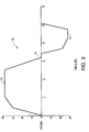
- the abscissa 310 represents the input percent digital coverage and the ordinate 312 the output digital percent coverage.
- the output may be comprised of small drops S m 302, big drops L n 306, or a combination of the two.
- small drops S m 302 increase at a slope of ml 314 (output percent digital coverage over input percent digital coverage) until the peak value (labeled Peak) 316 is reached.
- large drops L n 306 begin replacing small drops S m 302 until no small drops S m 302 remain (labeled Max) 320.
- slopes m2 318 and m3 322 are inverse of one another. Beyond the input point corresponding to Max 320, all small drops S m 302 have been replaced and large drops L n 306 continue to fill the grid 300 according to slope m4 324, which may be adjusted somewhat according to desired tone reproduction characteristics of mid to high optical density regions. Any further adjustments made to tone reproduction must be made is such a way so that the parameters described above are not overridden. Such image processing adjustments are made to the input request prior to image processing via the algorithm described above.
- Fig. 8 lists the specifics in tabular form implementing the algorithm of the present invention on an LP-3 printer as provided by the Tektronix Corporation. Therefore, Fig. 8 presents a final version of the drop size switching critical parameter usage for this type of printer. As shown, image quality and initial jetting robustness goals were met using the parameters under First Bitmap Implementation 332. In the First Postscript Implementation 336, small drop S m 302 usage was much greater than in the previous implementation, as can be seen by both the Peak 316 and Max 320 values and slopes ml 314 and m2 318. Jetting robustness issues at this operating point forced the operating frequency 334 to drop to 15 kHz. Even so, throughput goals were met.
- An ink jet printer includes a print head having multiple ink jets 10 as described above.
- Examples of an ink jet print head and an ink jet printer architecture are disclosed in U.S. Patent 5,677,718 entitled DROP-ON-DEMAND INK JET PRINT HEAD HAVING IMPROVED PURGING PERFORMANCE and U.S. Patent 5,389,958 entitled IMAGING PROCESS, both patents assigned to the assignee of the present application.
- U.S. Patents 5,677,718 and 5,389,958 are specifically incorporated by reference in pertinent part. It will be appreciated that other ink jet print head constructions and ink jet printer architectures may be utilized in practicing the present invention.
- the method and apparatus of the present invention may be practiced to jet various fluid types including, but not limited to, aqueous and phase-change inks of various colors.
- driving waveforms having various ink drop forming portions may be utilized.
- the second portion waveform 120 may precede the first portion waveform 110 in each cycle.
- this invention is useful in combination with various prior art techniques including dithering and electric field drop acceleration to provide enhanced image quality and drop landing accuracy.
- the present invention is amenable to any fluid jetting drive mechanism and architecture capable of providing the required drive waveform energy distribution to a suitable orifice and its fluid meniscus surface.
Applications Claiming Priority (4)
| Application Number | Priority Date | Filing Date | Title |
|---|---|---|---|
| US17249699P | 1999-12-17 | 1999-12-17 | |
| US172496P | 1999-12-17 | ||
| US738676 | 2000-12-14 | ||
| US09/738,676 US6629739B2 (en) | 1999-12-17 | 2000-12-14 | Apparatus and method for drop size switching in ink jet printing |
Publications (2)
| Publication Number | Publication Date |
|---|---|
| EP1108540A1 true EP1108540A1 (fr) | 2001-06-20 |
| EP1108540B1 EP1108540B1 (fr) | 2006-03-29 |
Family
ID=26868150
Family Applications (1)
| Application Number | Title | Priority Date | Filing Date |
|---|---|---|---|
| EP00127697A Expired - Lifetime EP1108540B1 (fr) | 1999-12-17 | 2000-12-18 | Appareil et procédé pour changer la taille des gouttes pour l'impression jet d'encre |
Country Status (4)
| Country | Link |
|---|---|
| US (1) | US6629739B2 (fr) |
| EP (1) | EP1108540B1 (fr) |
| JP (1) | JP2001219584A (fr) |
| DE (1) | DE60026919T2 (fr) |
Cited By (2)
| Publication number | Priority date | Publication date | Assignee | Title |
|---|---|---|---|---|
| US7767266B2 (en) | 2002-07-18 | 2010-08-03 | Mydata Automation Ab | Jetting device and method at a jetting device |
| EP2644387A1 (fr) * | 2012-03-28 | 2013-10-02 | Dainippon Screen Mfg. Co., Ltd. | Procédé et appareil dýenregistrement dýimage |
Families Citing this family (36)
| Publication number | Priority date | Publication date | Assignee | Title |
|---|---|---|---|---|
| JP3600198B2 (ja) * | 2001-08-31 | 2004-12-08 | 日本碍子株式会社 | 液滴吐出装置 |
| US20040085374A1 (en) * | 2002-10-30 | 2004-05-06 | Xerox Corporation | Ink jet apparatus |
| DE10257004A1 (de) * | 2002-12-06 | 2004-06-17 | Steag Microparts Gmbh | Vorrichtung zur parallelen Dosierung von Flüssigkeiten |
| US6739690B1 (en) * | 2003-02-11 | 2004-05-25 | Xerox Corporation | Ink jet apparatus |
| US7021733B2 (en) * | 2003-11-05 | 2006-04-04 | Xerox Corporation | Ink jet apparatus |
| US7281778B2 (en) | 2004-03-15 | 2007-10-16 | Fujifilm Dimatix, Inc. | High frequency droplet ejection device and method |
| US8491076B2 (en) | 2004-03-15 | 2013-07-23 | Fujifilm Dimatix, Inc. | Fluid droplet ejection devices and methods |
| US20060066656A1 (en) * | 2004-09-28 | 2006-03-30 | Maher Colin G | Method for reducing dot placement errors in imaging apparatus |
| US7495721B2 (en) * | 2004-12-20 | 2009-02-24 | Xerox Corporation | Methods of printing filter material to fabricate color filter |
| EP1836056B1 (fr) | 2004-12-30 | 2018-11-07 | Fujifilm Dimatix, Inc. | Impression a jet d'encre |
| US8967044B2 (en) * | 2006-02-21 | 2015-03-03 | R.R. Donnelley & Sons, Inc. | Apparatus for applying gating agents to a substrate and image generation kit |
| US9463643B2 (en) | 2006-02-21 | 2016-10-11 | R.R. Donnelley & Sons Company | Apparatus and methods for controlling application of a substance to a substrate |
| CA2643249A1 (fr) | 2006-02-21 | 2007-08-30 | Moore Wallace North America, Inc. | Systemes et procedes d'impression variable haute vitesse |
| US8881651B2 (en) | 2006-02-21 | 2014-11-11 | R.R. Donnelley & Sons Company | Printing system, production system and method, and production apparatus |
| US8869698B2 (en) * | 2007-02-21 | 2014-10-28 | R.R. Donnelley & Sons Company | Method and apparatus for transferring a principal substance |
| ATE458615T1 (de) * | 2006-05-24 | 2010-03-15 | Oce Tech Bv | Verfahren zur gewinnung eines bildes und tintenstrahldrucker zur durchführung dieses verfahrens |
| US7988247B2 (en) | 2007-01-11 | 2011-08-02 | Fujifilm Dimatix, Inc. | Ejection of drops having variable drop size from an ink jet printer |
| WO2009025809A1 (fr) | 2007-08-20 | 2009-02-26 | Rr Donnelley | Composition à base de nanoparticules compatible avec l'impression par jet d'encre et procédés associés |
| US9701120B2 (en) | 2007-08-20 | 2017-07-11 | R.R. Donnelley & Sons Company | Compositions compatible with jet printing and methods therefor |
| US8057005B2 (en) * | 2007-10-15 | 2011-11-15 | Xerox Corporation | Drop mass calibration method based on drop positional feedback |
| DE102008030972A1 (de) * | 2008-06-30 | 2009-12-31 | OCé PRINTING SYSTEMS GMBH | Verfahren zur Ermittlung der Zeichenbreite von aus Druckpunkten aufgebauten Zeichen bei einem Druck- oder Kopiergerät |
| US8419145B2 (en) | 2008-07-25 | 2013-04-16 | Eastman Kodak Company | Inkjet printhead and method of printing with multiple drop volumes |
| US8393702B2 (en) | 2009-12-10 | 2013-03-12 | Fujifilm Corporation | Separation of drive pulses for fluid ejector |
| WO2013054319A1 (fr) | 2011-10-11 | 2013-04-18 | Hewlett-Packard Industrial Printing Ltd. | Génération de données pour commander l'éjection de gouttes d'encre |
| CN105073434B (zh) | 2012-12-27 | 2017-12-26 | 科迪华公司 | 用于打印油墨体积控制以在精确公差内沉积流体的方法和系统 |
| US11673155B2 (en) | 2012-12-27 | 2023-06-13 | Kateeva, Inc. | Techniques for arrayed printing of a permanent layer with improved speed and accuracy |
| JP2015096322A (ja) * | 2013-10-07 | 2015-05-21 | 株式会社ミマキエンジニアリング | 印刷装置、インクジェットヘッド、及び印刷方法 |
| CN107825886B (zh) | 2013-12-12 | 2020-04-14 | 科迪华公司 | 制造电子设备的方法 |
| US9302468B1 (en) * | 2014-11-14 | 2016-04-05 | Ming Xu | Digital customizer system and method |
| US9781307B2 (en) | 2014-11-14 | 2017-10-03 | Sawgrass Technologies, Inc. | Networked digital imaging customization |
| US10419644B2 (en) | 2014-11-14 | 2019-09-17 | Sawgrass Technologies, Inc. | Digital image processing network |
| US10827098B2 (en) | 2015-11-02 | 2020-11-03 | Sawgrass Technologies, Inc. | Custom product imaging method |
| US10827097B2 (en) | 2015-11-02 | 2020-11-03 | Sawgrass Technologies, Inc. | Product imaging |
| CN109476158B (zh) | 2016-10-25 | 2020-12-01 | 惠普发展公司,有限责任合伙企业 | 用于维持打印质量参数的打印机和方法 |
| US9975330B1 (en) | 2017-04-17 | 2018-05-22 | Xerox Corporation | System and method for generation of non-firing electrical signals for operation of ejectors in inkjet printheads |
| JP7052568B2 (ja) * | 2018-05-31 | 2022-04-12 | セイコーエプソン株式会社 | 印刷装置および電圧決定方法 |
Citations (10)
| Publication number | Priority date | Publication date | Assignee | Title |
|---|---|---|---|---|
| US3946398A (en) | 1970-06-29 | 1976-03-23 | Silonics, Inc. | Method and apparatus for recording with writing fluids and drop projection means therefor |
| US4639735A (en) | 1983-06-14 | 1987-01-27 | Canon Kabushiki Kaisha | Apparatus for driving liquid jet head |
| US4746935A (en) | 1985-11-22 | 1988-05-24 | Hewlett-Packard Company | Multitone ink jet printer and method of operation |
| US5124716A (en) | 1990-01-08 | 1992-06-23 | Tektronix, Inc. | Method and apparatus for printing with ink drops of varying sizes using a drop-on-demand ink jet print head |
| US5389958A (en) | 1992-11-25 | 1995-02-14 | Tektronix, Inc. | Imaging process |
| EP0738598A2 (fr) * | 1995-04-19 | 1996-10-23 | Seiko Epson Corporation | Dispositif d'entraînement pour projection de gouttellettes d'encre |
| US5677718A (en) | 1992-06-04 | 1997-10-14 | Tektronix, Inc. | Drop-on-demand ink jet print head having improved purging performance |
| US5689291A (en) | 1993-07-30 | 1997-11-18 | Tektronix, Inc. | Method and apparatus for producing dot size modulated ink jet printing |
| EP0827838A2 (fr) * | 1996-09-09 | 1998-03-11 | Seiko Epson Corporation | Imprimante à jet d'encre et méthode d'impression à jet d'encre |
| EP0962323A1 (fr) * | 1998-06-02 | 1999-12-08 | Seiko Epson Corporation | Imprimante, procédé d'impression, et support d'enregistrement pour la mise en oeuvre du procédé |
Family Cites Families (12)
| Publication number | Priority date | Publication date | Assignee | Title |
|---|---|---|---|---|
| US4499479A (en) | 1982-08-30 | 1985-02-12 | International Business Machines Corporation | Gray scale printing with ink jet drop-on demand printing head |
| US4680645A (en) | 1986-08-25 | 1987-07-14 | Hewlett-Packard Company | Method for rendering gray scale images with variable dot sizes |
| US5323247A (en) | 1990-12-04 | 1994-06-21 | Research Corporation Technologies | Method and apparatus for halftoning and inverse halftoning and the transmission of such images |
| US5111310A (en) | 1990-12-04 | 1992-05-05 | Research Technologies Corporation, Inc. | Method and apparatus for halftone rendering of a gray scale image using a blue noise mask |
| US5341228A (en) | 1990-12-04 | 1994-08-23 | Research Corporation Technologies | Method and apparatus for halftone rendering of a gray scale image using a blue noise mask |
| US5742405A (en) | 1995-01-26 | 1998-04-21 | Eastman Kodak Company | Method and system for forming multi-level halftone images from an input digital image |
| US5777757A (en) * | 1995-06-05 | 1998-07-07 | Apple Computer, Inc. | Method and system for halftoning |
| JP3264422B2 (ja) * | 1996-09-09 | 2002-03-11 | セイコーエプソン株式会社 | インクジェット式プリントヘッドの駆動装置及び駆動方法 |
| JP4032490B2 (ja) * | 1998-03-09 | 2008-01-16 | セイコーエプソン株式会社 | 印刷装置および印刷方法並びに記録媒体 |
| US6352335B1 (en) * | 1998-04-14 | 2002-03-05 | Seiko Epson Corporation | Bidirectional printing capable of recording one pixel with one of dot-sizes |
| JP3414325B2 (ja) * | 1998-07-03 | 2003-06-09 | セイコーエプソン株式会社 | 印刷装置および記録媒体 |
| JP3687381B2 (ja) * | 1998-12-21 | 2005-08-24 | セイコーエプソン株式会社 | 印刷装置、印刷方法および記録媒体 |
-
2000
- 2000-12-14 US US09/738,676 patent/US6629739B2/en not_active Expired - Lifetime
- 2000-12-18 DE DE60026919T patent/DE60026919T2/de not_active Expired - Lifetime
- 2000-12-18 EP EP00127697A patent/EP1108540B1/fr not_active Expired - Lifetime
- 2000-12-18 JP JP2000384391A patent/JP2001219584A/ja active Pending
Patent Citations (10)
| Publication number | Priority date | Publication date | Assignee | Title |
|---|---|---|---|---|
| US3946398A (en) | 1970-06-29 | 1976-03-23 | Silonics, Inc. | Method and apparatus for recording with writing fluids and drop projection means therefor |
| US4639735A (en) | 1983-06-14 | 1987-01-27 | Canon Kabushiki Kaisha | Apparatus for driving liquid jet head |
| US4746935A (en) | 1985-11-22 | 1988-05-24 | Hewlett-Packard Company | Multitone ink jet printer and method of operation |
| US5124716A (en) | 1990-01-08 | 1992-06-23 | Tektronix, Inc. | Method and apparatus for printing with ink drops of varying sizes using a drop-on-demand ink jet print head |
| US5677718A (en) | 1992-06-04 | 1997-10-14 | Tektronix, Inc. | Drop-on-demand ink jet print head having improved purging performance |
| US5389958A (en) | 1992-11-25 | 1995-02-14 | Tektronix, Inc. | Imaging process |
| US5689291A (en) | 1993-07-30 | 1997-11-18 | Tektronix, Inc. | Method and apparatus for producing dot size modulated ink jet printing |
| EP0738598A2 (fr) * | 1995-04-19 | 1996-10-23 | Seiko Epson Corporation | Dispositif d'entraînement pour projection de gouttellettes d'encre |
| EP0827838A2 (fr) * | 1996-09-09 | 1998-03-11 | Seiko Epson Corporation | Imprimante à jet d'encre et méthode d'impression à jet d'encre |
| EP0962323A1 (fr) * | 1998-06-02 | 1999-12-08 | Seiko Epson Corporation | Imprimante, procédé d'impression, et support d'enregistrement pour la mise en oeuvre du procédé |
Cited By (5)
| Publication number | Priority date | Publication date | Assignee | Title |
|---|---|---|---|---|
| US7767266B2 (en) | 2002-07-18 | 2010-08-03 | Mydata Automation Ab | Jetting device and method at a jetting device |
| US8215535B2 (en) | 2002-07-18 | 2012-07-10 | Mydata Automation Ab | Jetting device and method at a jetting device |
| EP2644387A1 (fr) * | 2012-03-28 | 2013-10-02 | Dainippon Screen Mfg. Co., Ltd. | Procédé et appareil dýenregistrement dýimage |
| CN103358694A (zh) * | 2012-03-28 | 2013-10-23 | 大日本网屏制造株式会社 | 图像记录装置以及图像记录方法 |
| US9102165B2 (en) | 2012-03-28 | 2015-08-11 | SCREEN Holdings Co., Ltd. | Image recording apparatus and image recording method |
Also Published As
| Publication number | Publication date |
|---|---|
| DE60026919T2 (de) | 2006-08-17 |
| DE60026919D1 (de) | 2006-05-18 |
| JP2001219584A (ja) | 2001-08-14 |
| EP1108540B1 (fr) | 2006-03-29 |
| US20010022596A1 (en) | 2001-09-20 |
| US6629739B2 (en) | 2003-10-07 |
Similar Documents
| Publication | Publication Date | Title |
|---|---|---|
| US6629739B2 (en) | Apparatus and method for drop size switching in ink jet printing | |
| US6305773B1 (en) | Apparatus and method for drop size modulated ink jet printing | |
| EP0721840B1 (fr) | Procédé et appareil d'impression à jet d'encre à modulation de la dimension des points imprimés | |
| US5495270A (en) | Method and apparatus for producing dot size modulated ink jet printing | |
| US6257689B1 (en) | Printer and method of printing | |
| US6331040B1 (en) | Method of driving ink jet recording head | |
| US5975672A (en) | Ink jet printing apparatus and method accommodating printing mode control | |
| JP3840144B2 (ja) | 閾値マトリクス、画像処理装置、画像形成装置及びプリンタドライバ | |
| US20070030297A1 (en) | Ink jet head driving method and apparatus | |
| US8434842B2 (en) | Liquid ejecting apparatus and method of controlling liquid ejecting apparatus | |
| EP1077134A1 (fr) | Impression utilisant plusieurs types de points a modes de formation differents avec une meme quantite d'encre | |
| US5764252A (en) | Method and apparatus for producing ink intensity modulated ink jet printing | |
| US6154228A (en) | Image recording device capable of preventing deviation of ink dot on recording medium | |
| US20110090272A1 (en) | Liquid ejecting apparatus and method of controlling liquid ejecting apparatus | |
| JP2863465B2 (ja) | 傾斜階調描写を生成する方法及び同描写を生成するためのプリントヘッド | |
| JP3830038B2 (ja) | 階調再現方法、閾値マトリクス、画像処理方法、画像処理装置、画像形成装置及びプリンタドライバ | |
| JP2005001221A (ja) | 中間調処理用マスク作成方法およびインクジェット記録装置 | |
| JP2004166163A (ja) | 階調再現方法、閾値マトリクス、画像処理方法、画像形成装置及びプリンタドライバ | |
| Korol et al. | Solid Ink Printing with Dynamic Drop Size Modulation | |
| JPH1158707A (ja) | インクジェットプリンタ | |
| JP2001130032A (ja) | インクジェットプリンタ |
Legal Events
| Date | Code | Title | Description |
|---|---|---|---|
| PUAI | Public reference made under article 153(3) epc to a published international application that has entered the european phase |
Free format text: ORIGINAL CODE: 0009012 |
|
| AK | Designated contracting states |
Kind code of ref document: A1 Designated state(s): DE FR GB |
|
| AX | Request for extension of the european patent |
Free format text: AL;LT;LV;MK;RO;SI |
|
| 17P | Request for examination filed |
Effective date: 20011220 |
|
| AKX | Designation fees paid |
Free format text: DE FR GB |
|
| 17Q | First examination report despatched |
Effective date: 20050221 |
|
| GRAP | Despatch of communication of intention to grant a patent |
Free format text: ORIGINAL CODE: EPIDOSNIGR1 |
|
| GRAS | Grant fee paid |
Free format text: ORIGINAL CODE: EPIDOSNIGR3 |
|
| GRAA | (expected) grant |
Free format text: ORIGINAL CODE: 0009210 |
|
| AK | Designated contracting states |
Kind code of ref document: B1 Designated state(s): DE FR GB |
|
| REG | Reference to a national code |
Ref country code: GB Ref legal event code: FG4D |
|
| REF | Corresponds to: |
Ref document number: 60026919 Country of ref document: DE Date of ref document: 20060518 Kind code of ref document: P |
|
| ET | Fr: translation filed | ||
| PLBE | No opposition filed within time limit |
Free format text: ORIGINAL CODE: 0009261 |
|
| STAA | Information on the status of an ep patent application or granted ep patent |
Free format text: STATUS: NO OPPOSITION FILED WITHIN TIME LIMIT |
|
| 26N | No opposition filed |
Effective date: 20070102 |
|
| REG | Reference to a national code |
Ref country code: FR Ref legal event code: PLFP Year of fee payment: 16 |
|
| REG | Reference to a national code |
Ref country code: FR Ref legal event code: PLFP Year of fee payment: 17 |
|
| PGFP | Annual fee paid to national office [announced via postgrant information from national office to epo] |
Ref country code: GB Payment date: 20161128 Year of fee payment: 17 Ref country code: FR Payment date: 20161121 Year of fee payment: 17 Ref country code: DE Payment date: 20161121 Year of fee payment: 17 |
|
| REG | Reference to a national code |
Ref country code: DE Ref legal event code: R119 Ref document number: 60026919 Country of ref document: DE |
|
| GBPC | Gb: european patent ceased through non-payment of renewal fee |
Effective date: 20171218 |
|
| REG | Reference to a national code |
Ref country code: FR Ref legal event code: ST Effective date: 20180831 |
|
| PG25 | Lapsed in a contracting state [announced via postgrant information from national office to epo] |
Ref country code: DE Free format text: LAPSE BECAUSE OF NON-PAYMENT OF DUE FEES Effective date: 20180703 Ref country code: FR Free format text: LAPSE BECAUSE OF NON-PAYMENT OF DUE FEES Effective date: 20180102 |
|
| PG25 | Lapsed in a contracting state [announced via postgrant information from national office to epo] |
Ref country code: GB Free format text: LAPSE BECAUSE OF NON-PAYMENT OF DUE FEES Effective date: 20171218 |