EP1108525A2 - Verfahren zur Herstellung eines Gegenstandes aus zumindest teilweise einem wiederverwendeten Material und der durch das Verfahren hergestellte Gegenstand - Google Patents
Verfahren zur Herstellung eines Gegenstandes aus zumindest teilweise einem wiederverwendeten Material und der durch das Verfahren hergestellte Gegenstand Download PDFInfo
- Publication number
- EP1108525A2 EP1108525A2 EP00115409A EP00115409A EP1108525A2 EP 1108525 A2 EP1108525 A2 EP 1108525A2 EP 00115409 A EP00115409 A EP 00115409A EP 00115409 A EP00115409 A EP 00115409A EP 1108525 A2 EP1108525 A2 EP 1108525A2
- Authority
- EP
- European Patent Office
- Prior art keywords
- continuous layer
- filling material
- primary continuous
- primary
- manufactured item
- Prior art date
- Legal status (The legal status is an assumption and is not a legal conclusion. Google has not performed a legal analysis and makes no representation as to the accuracy of the status listed.)
- Granted
Links
Images


Classifications
-
- B—PERFORMING OPERATIONS; TRANSPORTING
- B29—WORKING OF PLASTICS; WORKING OF SUBSTANCES IN A PLASTIC STATE IN GENERAL
- B29B—PREPARATION OR PRETREATMENT OF THE MATERIAL TO BE SHAPED; MAKING GRANULES OR PREFORMS; RECOVERY OF PLASTICS OR OTHER CONSTITUENTS OF WASTE MATERIAL CONTAINING PLASTICS
- B29B17/00—Recovery of plastics or other constituents of waste material containing plastics
- B29B17/0026—Recovery of plastics or other constituents of waste material containing plastics by agglomeration or compacting
- B29B17/0042—Recovery of plastics or other constituents of waste material containing plastics by agglomeration or compacting for shaping parts, e.g. multilayered parts with at least one layer containing regenerated plastic
-
- B—PERFORMING OPERATIONS; TRANSPORTING
- B29—WORKING OF PLASTICS; WORKING OF SUBSTANCES IN A PLASTIC STATE IN GENERAL
- B29K—INDEXING SCHEME ASSOCIATED WITH SUBCLASSES B29B, B29C OR B29D, RELATING TO MOULDING MATERIALS OR TO MATERIALS FOR MOULDS, REINFORCEMENTS, FILLERS OR PREFORMED PARTS, e.g. INSERTS
- B29K2105/00—Condition, form or state of moulded material or of the material to be shaped
- B29K2105/06—Condition, form or state of moulded material or of the material to be shaped containing reinforcements, fillers or inserts
-
- Y—GENERAL TAGGING OF NEW TECHNOLOGICAL DEVELOPMENTS; GENERAL TAGGING OF CROSS-SECTIONAL TECHNOLOGIES SPANNING OVER SEVERAL SECTIONS OF THE IPC; TECHNICAL SUBJECTS COVERED BY FORMER USPC CROSS-REFERENCE ART COLLECTIONS [XRACs] AND DIGESTS
- Y02—TECHNOLOGIES OR APPLICATIONS FOR MITIGATION OR ADAPTATION AGAINST CLIMATE CHANGE
- Y02W—CLIMATE CHANGE MITIGATION TECHNOLOGIES RELATED TO WASTEWATER TREATMENT OR WASTE MANAGEMENT
- Y02W30/00—Technologies for solid waste management
- Y02W30/50—Reuse, recycling or recovery technologies
- Y02W30/62—Plastics recycling; Rubber recycling
Definitions
- the present invention relates to a process for producing a manufactured item of an at least partly recycled material, as well as to the manufactured item obtained thereby.
- thermoplastic resins have a chemical structure enabling the same to melt for an indefinite number of times, whereas thermosetting resins, once polymerized, if they are exposed to high temperatures again, loose their features in an irreversible manner.
- thermoplastic type have less recovery problems than those of a thermosetting type; on the contrary, for the composite materials having thermosetting binding agents the resin cannot be easily recovered.
- thermosetting material of the thermosetting type is typically made possible by mechanical destruction or crushing of the manufactured item itself, so as to obtain a heterogeneous material made up of broken fibres, portions of fibres forming resin clots and resin granules.
- crushed thermosetting materials of different particle sizes can be obtained.
- the material can be used in the different production steps of other composite manufactured items where particular and definite mechanical features are not required.
- the solution of mixing this recycled material with the fresh binding resin was adopted in the past, so as to help in volume creation while cutting down use of integral and complete resistant fibres and/or fresh binding resin, thereby reaching a great reduction in costs.
- thermosetting resin due to the particular nature of the thermosetting resin and the intrinsic heterogeneity of the crushed material, the modalities according to which this material is distributed over the different regions of the manufactured item cannot be defined and managed in an accurate manner, above all in connection with a working process for creation of this manufactured item; in particular, in the presently existing production systems there is a tendency to distribute the material to be recycled in a substantially homogeneous manner over the whole manufactured item so that this recycling material affects all the regions of the manufactured item in the same way. Arrangement of the fibres and of all the material resulting from crushing is typically irregular and random so that it is not possible to establish whether the added material to be recycled brings important benefits in terms of increase of the structural capacities of the manufactured item.
- thermosetting binding agents are generally adopted and for which during the production cycle a step is made necessary in which the glass fibres are chemically treated to ensure adhesion between the fibres themselves and the binding agent.
- the technical task underlying the present invention is to conceive a manufactured item of a material at least partly recycled (and a production process to make the same) capable of substantially obviating the mentioned limits.
- the technical task underlying the present invention is to conceive a process for producing a manufactured item of an at least partly recycled material capable of ensuring a real stability in coupling between the binding resin, the resistant fibres and the recycled material, so as to combine the advantageous use of low-cost materials with the substantial determination of the mechanical properties of the new manufactured item.
- Another important aim of the present invention is to find a process ensuring a distribution of the recycled material over predetermined regions and according to substantially pre-established arrangements within the new manufactured item.
- a further aim of the present invention is to devise a methodology ensuring use of the recycled material in a manner adapted to exploit the mechanical properties of the recycled fibre lengths to some extent.
- a further aim of the present invention is to devise a production process enabling an extensive use of materials from recycling operations, which will bring about advantages in terms of reduction of the environmental impact and re-use of poorly bio-degradable material.
- a still further aim of the present invention is to devise a process of simple implementation, as well as a manufactured item capable of being handled and/or used without requiring particularly skilled manpower, which will be advantageous as regards facility of use and reduction in costs.
- Another aim of the invention is to devise a process and a manufactured item having low manufacturing and installation costs.
- first arrangement of a primary continuous layer 2a and arrangement of a filling material 3 to be associated with the primary continuous layer 2a is provided.
- the primary continuous layer 2a may have a wide variety of possible embodiments, depending on the required functional qualities: for instance, the primary continuous layer 2a can be made of reinforcing fibres (glass fibres and/or aramidic fibres and/or carbon fibres and/or other fibres), or it may comprise a plurality of yarns oriented in a parallel direction, a felt of nonwoven fabric (of polyester or cellulose, for example) or a true fabric; the continuous layer may also comprise any combination of fabric and/or felt and/or parallel yarns.
- reinforcing fibres glass fibres and/or aramidic fibres and/or carbon fibres and/or other fibres
- the continuous layer may also comprise any combination of fabric and/or felt and/or parallel yarns.
- the primary continuous layer 2a can be made of a sheet element of polymeric material which in turn can be a thermoplastic or thermosetting material; in other words, the primary continuous layer 2a can be a very thin film of plastic material; in this case, the primary continuous layer 2a only acts as a receptacle for the filling material 3, but it does not show important mechanical features (except for the minimum structural cohesion required for its movement during the production process).
- the filling material 3 is on the contrary obtained from previous crushing operations carried out on the manufactured items made of composite material to be recycled, preferably of a thermosetting type, which operations in turn involve at least one grinding step. At the end of these operations the obtained filling material is in the form of different corpuscles or particles: resin and/or fibre powder, agglomerates of broken fibres and resin, lengths of isolated fibres and heterogenous resin clots.
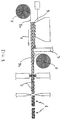
- the filling material 3 is required to be associated with the primary continuous layer 2a itself; this operation can be performed following different modalities such as for instance by drop of the filling material 3 from a hopper onto the primary continuous layer 2a set in motion by a conveyor belt (or other conventional devices such as rollers and the like) along a first operating direction 4.
- the step of setting the primary continuous layer 2a takes place by causing the primary continuous layer 2a to move forward along this first operating direction 4; during this forward movement, all working operations are carried out until the manufactured item 1 is obtained.
- the primary continuous layer 2a must offer such an interface surface with the filling material 3 that said material is unable to pass therethrough.
- the primary continuous layer 2a generally defines a continuous or netlike structure the mesh sizes of which are capable of preventing the filling material 2 from passing therethrough.
- a further step of the process involves the operation of mechanically linking the filling material 3 to the primary continuous layer 2a.
- This step can be typically obtained, by means of seaming lines 5 steadily engaging the different particle types characterizing the filling material 3 with the primary continuous layer 2a.
- the production process in accordance with the invention may provide for use of different systems of mechanical linking, such as by means of thread lengths, rope lengths, or glueing.
- the manufactured item 1 By mechanically linking the filling material 3 to the primary continuous layer 2a, the manufactured item 1 generally shown in the drawings is essentially defined.
- the step of associating the filling material 3 with the primary continuous layer 2a involves a sub-step of positioning the filling material 3 according to a predetermined geometric arrangement on the primary continuous layer 2a; obviously, selection of the particular geometric arrangement according to which the filling material 3 will be laid down on the primary continuous layer 2a is done each time, depending on the deformability and/or swelling or blowing features desired for the manufactured item 1.
- positioning of the filling material 3 can be obtained for instance by deposition of the filling material 3 on part or even all of the surface of the primary continuous layer 2a.
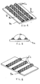
- the filling material 3 can be laid down in a predetermined number of longitudinal filling lines 6a (that can be continuous or broken, as viewed from Fig. 4) substantially parallel to the first operating direction 4; preferably, these longitudinal filling lines 6a are spaced apart the same distance from each other, for easy accomplishment and in order to ensure some structural regularity to the manufactured item 1.
- deposition of the filling material 3 can be also obtained in a predetermined number of transverse filling lines 6b (which may be continuous or broken as well), substantially oriented transversely (and preferably perpendicularly) of the first operating direction 4; in this case too, for the same reasons described above, these transverse filling lines 6b can be spaced apart the same distance from each other.
- filling material 3 onto the primary continuous layer 2a according to a predetermined arrangement of discrete filling areas 6c, in the form of cones or spherical portions for example, or generally having any polyhedric shape and disposed in an arbitrary pattern relative to each other.
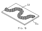
- a further alternative embodiment of the filling material positioning can be obtained in accordance with predetermined filling routes 6d; these filling routes 6d can follow any trajectory, and generally comprise a plurality of curved portions (but they may also consist of broken lines).
- the production process of the invention is such conceived that the sub-step of positioning the filling material 3 can be accomplished through a predetermined combination of longitudinal filling lines 6a and/or transverse filling lines 6b and/or discrete filling areas 6c and/or filling routes 6d, so as to ensure maximum adaptability of the manufactured item 1 to the most varied use conditions.
- the process of the present invention also involves a step of adjusting a deposition height of the filling material 3 associated with the primary continuous layer 2a; this operation can be obtained by control of the feeding speed of the primary continuous layer 2a along the first operating direction 4 (so that the filling material falling thereon will have more or less time for accumulating); alternatively, adjustment of the deposition height is obtained by control of the dropping speed and/or flow rate of the filling material 3 on the primary continuous layer 2a, or by interaction of a height-adjusting member 7 (in the form of a horizontal partition placed to a given height from the primary continuous layer 2a running under it).
- the height-adjusting member 7 is operatively active on the filling material laid down on the primary continuous layer 2a to cause a maximum thickness of same and in particular to remove the excess filling material 3 accumulating on the primary continuous layer 2a during transportation (which is therefore moved away).
- this step of adjusting the deposition height of the filling material 3 takes place simultaneously with the step of associating the filling material 3 with the primary continuous layer 2a, so as to streamline the production process.
- the manufactured item 1 can be made in different structural typologies: for instance, a particularly advantageous embodiment involves the presence of a suitably-arranged secondary continuous layer 2b (disposed close to the primary continuous layer 2a, for example, and along to the first operating direction 4).
- the secondary continuous layer 2b is put close to the primary continuous layer 2a in such a manner that the filling material 3 is (at least partly) included between the two continuous layers 2a and 2b, so as to create a "sandwich" structure wherein the filling material 3 is confined in the gap defined by the two mutually-facing continuous layers 2a and 2b.
- the secondary continuous layer 2b can be embodied either by a sheet element of polymeric preferably thermoplastic material, or a fabric, a non-woven fabric, a paper structure or a plurality of yarns disposed in parallel side by side relationship.
- the secondary continuous layer 2b can be made of a multiplicity of reinforcing fibres, typically glass fibres and/or aramidic and/or carbon fibres or the like, organized in a fabric, a non-woven fabric, a paper structure or a plurality of yarns disposed in parallel side by side relationship.
- the step of setting the secondary continuous layer 2b comes after the step of associating the filling material 3 with the primary continuous layer 2a, clearly for the purpose of enabling correct deposition of the filling material itself; in this connection it should be recognized that, for the same reason as described above, the step of setting the secondary continuous layer 2b (that obviously follows the step of arranging the primary continuous layer 2a) is carried out after the step of adjusting the deposition height of the filling material 3.
- arrangement of the secondary continuous layer 2b takes place exactly in the same manner as described with reference to the primary continuous layer 2a; in particular, arrangement of the primary continuous layer 2a and/or the secondary continuous layer 2b is carried out by unrolling a source roll 8 along the first operating direction 4 (obviously, for each continuous layer a separate roll is to be unrolled).
- source rolls 8 essentially comprise a rolled-up sheet element, that obviously can be made of any combination of features as already described with reference to the continuous layers 2a and 2b.
- the continuous layers 2a and 2b can be in turn mutually engaged by means of one or more series of seaming lines 5 for example, or other similar means such as thread lengths, localized pressure on the opposed layers, rope lengths, or glueing.
- the continuous layers 2a and 2b are made of sheets of thermoplastic polymeric material, they can be linked to each other (and simultaneously confining of the filling material 3 can be carried out) by heat-sealing; heat-sealing can be obtained by pressing the manufactured item on opposite sides between two heating elements, so that the two plastic films are fused together and consequently a closed volume within which the material 3 is held is formed.
- the heating elements for instance, they can be such shaped that approaching of said heating elements to the manufactured item 1 helps in defining the longitudinal filling lines 6a and/or the transverse filling lines 6b and/or the discrete filling areas 6c and/or the filling routes 6d (see Figs.
- the through seaming lines 5 can be conveniently made along the perimeter of the primary continuous layer 2a and the secondary continuous layer 2b or over the whole surface of the continuous layers, depending on the desired results.
- seaming lines 5 pass through the filling material 3 for the purpose not only of linking layers 2a and 2b, but also of acting as locking elements to sliding of the different particles forming the filling material 3.
- an operating step which consists in associating at least one continuous stiffening layer 2c which will be able to have all possible construction embodiments already described as regards nature of the primary and secondary continuous layers 2a, 2b; in particular, the stiffening layer 2c can be made of reinforcing fibres, the nature and mutual arrangement of which substantially correspond to all possible embodiments already described for the continuous layers 2a and 2b. Addition of this stiffening layer 2c can be accomplished by linking the latter to either of the two continuous layers 2a or 2b, or even to both of them, depending on the mechanical capacities to be given to the manufactured item 1; obviously, if required, the stiffening layer can be associated with the primary continuous layer 2a alone.
- the above described process enables achievement of a manufactured item consisting of a primary continuous layer 2a (substantially in the form of a sheet element of a netlike structure having mesh sizes smaller than the average sizes of the particles defining the filling material 3) and a predetermined amount of filling material 3 associated with the primary continuous layer 2a through a plurality of mechanical linking elements (typically the seaming lines 5).
- the filling material 3 is associated with the primary continuous layer 2a according to a predetermined geometric arrangement over the primary continuous layer 2a itself, and in particular according to any combination of filling lines 6a, 6b, discrete filling areas 6c and/or filling routes 6d.
- the manufactured item 1 can have a secondary continuous layer 2b disposed close to the primary continuous layer 2a so that the filling material 3 is sandwiched between the two layers 2a and 2b.
- the manufactured item may comprise one or more stiffening layers 2c associated with either or both of the primary and secondary continuous layers 2a, 2b.
- layers 2a, 2b and 2c substantially are sheet elements, made of polymeric material and/or reinforcing fibres, the nature and arrangement of which correspond to the above description.
- an industrial apparatus for putting into practice the process for producing the manufactured item 1 made of an at least partly recycled material in accordance with the present invention.
- the manufactured item of a reinforcing fibre with a sheet-like structure which is obtained with the process of the present invention can be advantageously employed in different applications, in making section members preferably obtained by pultrusion, for example.
- the following steps take place in succession: producing the manufactured item 1 with the above described process of the invention, impregnating the sheet-like manufactured item thus obtained with a binding substance, forming the section of the section member by forced passage through a cavity of pre-established shape (or an extruder through which partial or complete polymerisation of the resin takes place) and finally executing possible transverse cuts on the section member coming out of the moulding extruder so as to obtain finished articles of the desired length.
- the article obtained from this production process substantially is a section member of composite material, the portion of which adapted to resist mechanical stresses comprises the sheet-like manufactured item obtained with the process of the present invention.
- the core of the sheet-like manufactured item in which the filling material is stably positioned during the moulding step of the section member occupies parts of the section thereof that are not submitted to important stresses during use; on the contrary, the continuous layers 2a and 2b external to the filling material 2 can be advantageously disposed where important efforts are expected to occur, in particular tensile stresses. Due to the possibility of managing positioning of the filling material 2 in a precise manner, there is a saving in terms both of added fibres and added binding resin without any decay of the mechanical properties of the section member.
- the manufactured item of reinforcing fibre in particular in the embodiment involving the presence of more than one continuous layer of reinforcing fibre, advantageously finds application in the construction of support posts of tubular structure.
- These posts are manufactured by a production process comprising the following essential steps: arranging a plurality of manufactured items of reinforcing fibre and produced with the process of the invention and of different lengths; winding the sheet-like supports around a mandrel; introducing the mandrel holding the manufactured items into a rotating chamber and finally impregnating the sheet-like supports with a binding substance by centrifugation.
- posts of varying section are obtained, in particular tapering posts.
- the manufactured items are such arranged that one of the two continuous layers of reinforcing fibre of each manufactured item is turned inwardly (i.e. towards the cylindrical cavity of the tubular post) and the other continuous layer is turned outwardly.
- the two continuous layers enclose the filling material. In this way the continuous layers withstand the mechanical stresses, whereas the filling material stabilizes the laminate improving behaviour of same towards flexion and compression loads.
- finished or semifinished products can be made in which the filling material is confined to regions of the product where weak mechanical stresses, in particular tensile stresses are present.
- the filling material gives the section important properties such as a high moment of inertia; in the case of the above mentioned posts the filling material 2 is substantially positioned at an annulus disposed in an intermediate region of the post section, between the inner wall and outer wall of the post itself.
- the invention achieves important advantages.
- the intrinsic simplicity of the process enables the plants to have a high productivity due to the high operating speed in carrying out the described operations.
- the process enables manufacture of an item mostly made up of recycled material, which will bring about an important recovery of discarded articles for which disposal would be difficult, thereby reducing the environmental impact.
- Another advantage resulting from applying this process to production of a manufactured article made of glass fibre resides in that the fibre lengths present in the recycling material are mechanically linked to the glass fibres really working in the manufactured item, which will improve resistance to mechanical stresses.
- use of material from crushing is also useful when volume occupation is necessary, for instance in structural elements that must be provided with excellent stability to compression stresses, since in this way big spaces can be filled without use of new resistant fibres where too strong efforts (in particular tensile stresses) are not required. Therefore, in this case there is an important reduction in the used-material costs above all by introducing materials otherwise unusable into the production cycle.
- the filling material 3 suitably positioned enables the moment of inertia of the sections of the products in which it is used (section members, posts and the like) to be increased, thereby promoting efficiency of the working portions (new fibres) of the finished composite article.
- the process of the invention reduces the production costs and greatly simplifies the manufacturing processes, since the employed materials are relatively cheap and the dedicated plants are of simple construction and operation.
Landscapes
- Engineering & Computer Science (AREA)
- Environmental & Geological Engineering (AREA)
- Mechanical Engineering (AREA)
- Laminated Bodies (AREA)
- Processing And Handling Of Plastics And Other Materials For Molding In General (AREA)
- Reinforced Plastic Materials (AREA)
Priority Applications (2)
| Application Number | Priority Date | Filing Date | Title |
|---|---|---|---|
| EP20000115409 EP1108525B1 (de) | 1999-12-15 | 2000-07-17 | Verfahren zur Herstellung eines Gegenstandes aus zumindest teilweise einem wiederverwendeten Material und der durch das Verfahren hergestellte Gegenstand |
| US09/737,315 US6623575B2 (en) | 1999-12-15 | 2000-12-14 | Method for producing a manufactured item at least partly in recycled material, and the manufactured item so obtained |
Applications Claiming Priority (3)
| Application Number | Priority Date | Filing Date | Title |
|---|---|---|---|
| EP19990830779 EP1110706A1 (de) | 1999-12-15 | 1999-12-15 | Faserverstärkte Struktur und Verfahren zu ihrer Herstellung |
| EP99830779 | 1999-12-15 | ||
| EP20000115409 EP1108525B1 (de) | 1999-12-15 | 2000-07-17 | Verfahren zur Herstellung eines Gegenstandes aus zumindest teilweise einem wiederverwendeten Material und der durch das Verfahren hergestellte Gegenstand |
Publications (3)
| Publication Number | Publication Date |
|---|---|
| EP1108525A2 true EP1108525A2 (de) | 2001-06-20 |
| EP1108525A3 EP1108525A3 (de) | 2003-07-09 |
| EP1108525B1 EP1108525B1 (de) | 2009-10-14 |
Family
ID=26071177
Family Applications (1)
| Application Number | Title | Priority Date | Filing Date |
|---|---|---|---|
| EP20000115409 Expired - Lifetime EP1108525B1 (de) | 1999-12-15 | 2000-07-17 | Verfahren zur Herstellung eines Gegenstandes aus zumindest teilweise einem wiederverwendeten Material und der durch das Verfahren hergestellte Gegenstand |
Country Status (2)
| Country | Link |
|---|---|
| US (1) | US6623575B2 (de) |
| EP (1) | EP1108525B1 (de) |
Families Citing this family (4)
| Publication number | Priority date | Publication date | Assignee | Title |
|---|---|---|---|---|
| CA2277472A1 (en) * | 1997-01-10 | 1998-07-16 | Falke Garne Kg | Flat structure, in particular a non-woven fabric |
| DE10132103C1 (de) * | 2001-07-03 | 2003-04-30 | Filzfabrik Fulda Gmbh | Verfahren zur Herstellung eines gemusterten textilen Flächengebildes |
| US20070011987A1 (en) * | 2005-04-29 | 2007-01-18 | Mcaleenan Michael | Joiner panel system |
| JP7054499B2 (ja) * | 2017-06-06 | 2022-04-14 | サンコロナ小田株式会社 | 繊維強化熱可塑性樹脂シートの製造方法 |
Family Cites Families (9)
| Publication number | Priority date | Publication date | Assignee | Title |
|---|---|---|---|---|
| US3684645A (en) * | 1969-03-25 | 1972-08-15 | Ppg Industries Inc | Glass fiber reinforced thermoplastic article |
| US3614936A (en) * | 1969-05-09 | 1971-10-26 | Owens Corning Fiberglass Corp | Nonwoven reinforcement structure and method for producing it |
| FR2628448B1 (fr) * | 1988-03-14 | 1990-11-16 | Chomarat & Cie | Armature textile utilisable pour la realisation de complexes stratifies et complexes stratifies en forme comportant une telle armature |
| US5169571A (en) * | 1991-04-16 | 1992-12-08 | The C.A. Lawton Company | Mat forming process and apparatus |
| US5759927A (en) * | 1995-07-24 | 1998-06-02 | Meeker; Brian L. | Glass-fiber-containing non-woven polymer web, and process for preparing same |
| US5665185A (en) * | 1996-02-09 | 1997-09-09 | Esfi Acquisition, Inc. | Process for preparing glass fiber containing polymer sheet |
| US5743985A (en) * | 1996-10-31 | 1998-04-28 | Owens-Corning Fiberglas Technology, Inc. | Method of making an asphalt and fiber laminated insulation product |
| WO1998053978A1 (en) * | 1997-05-30 | 1998-12-03 | Ppg Industries Ohio, Inc. | Glass fiber mats, composites reinforced with the same and methods for making the same |
| US6156682A (en) * | 1998-09-18 | 2000-12-05 | Findlay Industries, Inc. | Laminated structures with multiple denier polyester core fibers, randomly oriented reinforcement fibers, and methods of manufacture |
-
2000
- 2000-07-17 EP EP20000115409 patent/EP1108525B1/de not_active Expired - Lifetime
- 2000-12-14 US US09/737,315 patent/US6623575B2/en not_active Expired - Fee Related
Also Published As
| Publication number | Publication date |
|---|---|
| EP1108525B1 (de) | 2009-10-14 |
| US20010003858A1 (en) | 2001-06-21 |
| EP1108525A3 (de) | 2003-07-09 |
| US6623575B2 (en) | 2003-09-23 |
Similar Documents
| Publication | Publication Date | Title |
|---|---|---|
| CA1331733C (en) | Process for continuously forming reinforced articles | |
| US5492580A (en) | Nonwoven moldable composite and method of manufacture | |
| EP0285705B1 (de) | Verstärkungen für das kontinuierliche Ziehen von aus verstärkten Kunststoffen bestehenden Produkten und neue, durch Pultrusion hergestellte Produkte | |
| US3889035A (en) | Fiber-reinforced plastic articles | |
| US20060125156A1 (en) | Method of production of composite materials | |
| KR20050091002A (ko) | 복합 시트의 제조방법 및 이를 위한 디바이스 | |
| DE202011110971U1 (de) | Paneel, umfassend eine Polymerverbundwerkstofflage und eine Verstärkungslage | |
| KR20100024931A (ko) | 보강 직물 아마추어 및 그 제조 방법 | |
| JP2000017605A (ja) | 人工芝生 | |
| US6623575B2 (en) | Method for producing a manufactured item at least partly in recycled material, and the manufactured item so obtained | |
| US20050170731A1 (en) | Fibrous structure which is used to produce composite materials | |
| CN102482820A (zh) | 具有连续玻璃纤维的织物芯 | |
| US4487647A (en) | Process and device for the continuous production of glass fiber reinforced sheets of thermoplastic polymers | |
| WO2002026463A2 (en) | Process of making simultaneously molded laminates | |
| JP2001521449A (ja) | 複合体およびその製造方法 | |
| US5585455A (en) | Reinforcement composites for thermosetting polymer systems | |
| WO2004030906A1 (en) | Composite materials | |
| JP2006512501A5 (de) | ||
| FI119846B (fi) | Lujitemateriaali käytettäväksi tekstiililujitteena komposiiteissa | |
| WO1995028265A1 (de) | Verfahren und anlage zur herstellung von verformbaren halbzeugmatten | |
| EP0439469B2 (de) | Mit kontinuierlichen fasern verstärktes kompositraster mit hohem wirkungsgrad | |
| JPS58167152A (ja) | 繊維強化シ−トの連続的製造法 | |
| EP3883759A1 (de) | Verfahren zur herstellung eines verbundstoffs | |
| EP1110706A1 (de) | Faserverstärkte Struktur und Verfahren zu ihrer Herstellung | |
| GB2259048A (en) | A mesh structure/fabric laminate |
Legal Events
| Date | Code | Title | Description |
|---|---|---|---|
| PUAI | Public reference made under article 153(3) epc to a published international application that has entered the european phase |
Free format text: ORIGINAL CODE: 0009012 |
|
| AK | Designated contracting states |
Kind code of ref document: A2 Designated state(s): AT BE CH CY DE DK ES FI FR GB GR IE IT LI LU MC NL PT SE |
|
| AX | Request for extension of the european patent |
Free format text: AL;LT;LV;MK;RO;SI |
|
| RIC1 | Information provided on ipc code assigned before grant |
Ipc: 7B 29B 17/00 B Ipc: 7B 29C 70/08 A Ipc: 7B 29C 70/54 B |
|
| PUAL | Search report despatched |
Free format text: ORIGINAL CODE: 0009013 |
|
| AK | Designated contracting states |
Designated state(s): AT BE CH CY DE DK ES FI FR GB GR IE IT LI LU MC NL PT SE |
|
| AX | Request for extension of the european patent |
Extension state: AL LT LV MK RO SI |
|
| 17P | Request for examination filed |
Effective date: 20030930 |
|
| AKX | Designation fees paid |
Designated state(s): AT BE CH CY DE DK ES FI FR GB GR IE IT LI LU MC NL PT SE |
|
| AXX | Extension fees paid |
Extension state: RO Payment date: 20031117 |
|
| RAP1 | Party data changed (applicant data changed or rights of an application transferred) |
Owner name: TOP GLASS S.P.A. |
|
| 17Q | First examination report despatched |
Effective date: 20051020 |
|
| GRAP | Despatch of communication of intention to grant a patent |
Free format text: ORIGINAL CODE: EPIDOSNIGR1 |
|
| GRAS | Grant fee paid |
Free format text: ORIGINAL CODE: EPIDOSNIGR3 |
|
| GRAA | (expected) grant |
Free format text: ORIGINAL CODE: 0009210 |
|
| AK | Designated contracting states |
Kind code of ref document: B1 Designated state(s): AT BE CH CY DE DK ES FI FR GB GR IE IT LI LU MC NL PT SE |
|
| AX | Request for extension of the european patent |
Extension state: RO |
|
| REG | Reference to a national code |
Ref country code: GB Ref legal event code: FG4D |
|
| REG | Reference to a national code |
Ref country code: CH Ref legal event code: EP |
|
| REG | Reference to a national code |
Ref country code: IE Ref legal event code: FG4D |
|
| REF | Corresponds to: |
Ref document number: 60043143 Country of ref document: DE Date of ref document: 20091126 Kind code of ref document: P |
|
| NLV1 | Nl: lapsed or annulled due to failure to fulfill the requirements of art. 29p and 29m of the patents act | ||
| REG | Reference to a national code |
Ref country code: ES Ref legal event code: FG2A Ref document number: 2337229 Country of ref document: ES Kind code of ref document: T3 |
|
| PG25 | Lapsed in a contracting state [announced via postgrant information from national office to epo] |
Ref country code: SE Free format text: LAPSE BECAUSE OF FAILURE TO SUBMIT A TRANSLATION OF THE DESCRIPTION OR TO PAY THE FEE WITHIN THE PRESCRIBED TIME-LIMIT Effective date: 20091014 Ref country code: FI Free format text: LAPSE BECAUSE OF FAILURE TO SUBMIT A TRANSLATION OF THE DESCRIPTION OR TO PAY THE FEE WITHIN THE PRESCRIBED TIME-LIMIT Effective date: 20091014 Ref country code: PT Free format text: LAPSE BECAUSE OF FAILURE TO SUBMIT A TRANSLATION OF THE DESCRIPTION OR TO PAY THE FEE WITHIN THE PRESCRIBED TIME-LIMIT Effective date: 20100215 |
|
| PG25 | Lapsed in a contracting state [announced via postgrant information from national office to epo] |
Ref country code: AT Free format text: LAPSE BECAUSE OF FAILURE TO SUBMIT A TRANSLATION OF THE DESCRIPTION OR TO PAY THE FEE WITHIN THE PRESCRIBED TIME-LIMIT Effective date: 20091014 |
|
| PG25 | Lapsed in a contracting state [announced via postgrant information from national office to epo] |
Ref country code: DK Free format text: LAPSE BECAUSE OF FAILURE TO SUBMIT A TRANSLATION OF THE DESCRIPTION OR TO PAY THE FEE WITHIN THE PRESCRIBED TIME-LIMIT Effective date: 20091014 |
|
| PLBE | No opposition filed within time limit |
Free format text: ORIGINAL CODE: 0009261 |
|
| STAA | Information on the status of an ep patent application or granted ep patent |
Free format text: STATUS: NO OPPOSITION FILED WITHIN TIME LIMIT |
|
| 26N | No opposition filed |
Effective date: 20100715 |
|
| PG25 | Lapsed in a contracting state [announced via postgrant information from national office to epo] |
Ref country code: GR Free format text: LAPSE BECAUSE OF FAILURE TO SUBMIT A TRANSLATION OF THE DESCRIPTION OR TO PAY THE FEE WITHIN THE PRESCRIBED TIME-LIMIT Effective date: 20100115 |
|
| PG25 | Lapsed in a contracting state [announced via postgrant information from national office to epo] |
Ref country code: MC Free format text: LAPSE BECAUSE OF NON-PAYMENT OF DUE FEES Effective date: 20100731 |
|
| REG | Reference to a national code |
Ref country code: CH Ref legal event code: PL |
|
| PG25 | Lapsed in a contracting state [announced via postgrant information from national office to epo] |
Ref country code: CH Free format text: LAPSE BECAUSE OF NON-PAYMENT OF DUE FEES Effective date: 20100731 Ref country code: LI Free format text: LAPSE BECAUSE OF NON-PAYMENT OF DUE FEES Effective date: 20100731 |
|
| PG25 | Lapsed in a contracting state [announced via postgrant information from national office to epo] |
Ref country code: IE Free format text: LAPSE BECAUSE OF NON-PAYMENT OF DUE FEES Effective date: 20100717 |
|
| PGFP | Annual fee paid to national office [announced via postgrant information from national office to epo] |
Ref country code: GB Payment date: 20110713 Year of fee payment: 12 Ref country code: ES Payment date: 20110817 Year of fee payment: 12 |
|
| PG25 | Lapsed in a contracting state [announced via postgrant information from national office to epo] |
Ref country code: CY Free format text: LAPSE BECAUSE OF FAILURE TO SUBMIT A TRANSLATION OF THE DESCRIPTION OR TO PAY THE FEE WITHIN THE PRESCRIBED TIME-LIMIT Effective date: 20091014 |
|
| PG25 | Lapsed in a contracting state [announced via postgrant information from national office to epo] |
Ref country code: LU Free format text: LAPSE BECAUSE OF NON-PAYMENT OF DUE FEES Effective date: 20100717 Ref country code: NL Free format text: LAPSE BECAUSE OF FAILURE TO SUBMIT A TRANSLATION OF THE DESCRIPTION OR TO PAY THE FEE WITHIN THE PRESCRIBED TIME-LIMIT Effective date: 20091014 |
|
| GBPC | Gb: european patent ceased through non-payment of renewal fee |
Effective date: 20120717 |
|
| PG25 | Lapsed in a contracting state [announced via postgrant information from national office to epo] |
Ref country code: GB Free format text: LAPSE BECAUSE OF NON-PAYMENT OF DUE FEES Effective date: 20120717 |
|
| REG | Reference to a national code |
Ref country code: ES Ref legal event code: FD2A Effective date: 20131018 |
|
| PG25 | Lapsed in a contracting state [announced via postgrant information from national office to epo] |
Ref country code: ES Free format text: LAPSE BECAUSE OF NON-PAYMENT OF DUE FEES Effective date: 20120718 |
|
| REG | Reference to a national code |
Ref country code: FR Ref legal event code: PLFP Year of fee payment: 16 |
|
| PGFP | Annual fee paid to national office [announced via postgrant information from national office to epo] |
Ref country code: DE Payment date: 20150714 Year of fee payment: 16 |
|
| PGFP | Annual fee paid to national office [announced via postgrant information from national office to epo] |
Ref country code: BE Payment date: 20150713 Year of fee payment: 16 Ref country code: FR Payment date: 20150629 Year of fee payment: 16 |
|
| PG25 | Lapsed in a contracting state [announced via postgrant information from national office to epo] |
Ref country code: BE Free format text: LAPSE BECAUSE OF NON-PAYMENT OF DUE FEES Effective date: 20160731 |
|
| REG | Reference to a national code |
Ref country code: DE Ref legal event code: R119 Ref document number: 60043143 Country of ref document: DE |
|
| PG25 | Lapsed in a contracting state [announced via postgrant information from national office to epo] |
Ref country code: DE Free format text: LAPSE BECAUSE OF NON-PAYMENT OF DUE FEES Effective date: 20170201 Ref country code: FR Free format text: LAPSE BECAUSE OF NON-PAYMENT OF DUE FEES Effective date: 20160801 |
|
| REG | Reference to a national code |
Ref country code: FR Ref legal event code: ST Effective date: 20170331 |
|
| PGFP | Annual fee paid to national office [announced via postgrant information from national office to epo] |
Ref country code: IT Payment date: 20190719 Year of fee payment: 20 |