EP1108494A2 - Ultrasonic vibration cutting tool and production method thereof - Google Patents
Ultrasonic vibration cutting tool and production method thereof Download PDFInfo
- Publication number
- EP1108494A2 EP1108494A2 EP00126633A EP00126633A EP1108494A2 EP 1108494 A2 EP1108494 A2 EP 1108494A2 EP 00126633 A EP00126633 A EP 00126633A EP 00126633 A EP00126633 A EP 00126633A EP 1108494 A2 EP1108494 A2 EP 1108494A2
- Authority
- EP
- European Patent Office
- Prior art keywords
- blade
- ultrasonic vibration
- ring
- shaped projection
- resonator
- Prior art date
- Legal status (The legal status is an assumption and is not a legal conclusion. Google has not performed a legal analysis and makes no representation as to the accuracy of the status listed.)
- Ceased
Links
Images


Classifications
-
- B—PERFORMING OPERATIONS; TRANSPORTING
- B23—MACHINE TOOLS; METAL-WORKING NOT OTHERWISE PROVIDED FOR
- B23P—METAL-WORKING NOT OTHERWISE PROVIDED FOR; COMBINED OPERATIONS; UNIVERSAL MACHINE TOOLS
- B23P15/00—Making specific metal objects by operations not covered by a single other subclass or a group in this subclass
- B23P15/28—Making specific metal objects by operations not covered by a single other subclass or a group in this subclass cutting tools
-
- B—PERFORMING OPERATIONS; TRANSPORTING
- B23—MACHINE TOOLS; METAL-WORKING NOT OTHERWISE PROVIDED FOR
- B23K—SOLDERING OR UNSOLDERING; WELDING; CLADDING OR PLATING BY SOLDERING OR WELDING; CUTTING BY APPLYING HEAT LOCALLY, e.g. FLAME CUTTING; WORKING BY LASER BEAM
- B23K20/00—Non-electric welding by applying impact or other pressure, with or without the application of heat, e.g. cladding or plating
- B23K20/10—Non-electric welding by applying impact or other pressure, with or without the application of heat, e.g. cladding or plating making use of vibrations, e.g. ultrasonic welding
Definitions
- the present invention relates to an ultrasonic vibration cutting tool and to a production method thereof.
- Ultrasonic vibration cutting tools are divided into two types: an integrated type in which a blade projecting outward from the peripheral surface of a resonator is integrated with the resonator and a separate type in which a disk-like blade is attached to a resonator. Since the blade and the resonator are made from the same material in the case of the integrated type, when the blade is formed from a material best suited for a member to be cut, the material of the resonator may not have excellent acoustic characteristics, or when the resonator is formed from a material having excellent acoustic characteristics, the material of the blade has poor compatibility with the member to be cut. Therefore, the material of the blade is limited inevitably.
- the blade and the resonator can be formed from different materials.
- the blade is formed from a material best suited for a member to be cut and the resonator is formed from a material having excellent acoustic characteristics.
- the transmission efficiency of ultrasonic vibration from the resonator to the blade becomes worse inevitably compared with the integrated type.
- the present invention provides an ultrasonic vibration rotary cutting tool which can optimize materials as in a separate type and can improve the transmission efficiency of ultrasonic vibration as in an integrated type, as well as a production method thereof.
- an ultrasonic vibration cutting tool comprising a ring-shaped projection and a blade essentially composed of diamond and held by the ring-shaped projection, all of which are formed on the peripheral surface of a vibration conversion portion provided on a resonator, wherein the outer diameter of the blade is made larger than the outer diameter of the ring-shaped projection.
- the blade is formed from a material best suited for a member to be cut regardless of the resonator and integrated with the resonator. Therefore, the optimization of materials as in the separate type and the improvement of the transmission efficiency of ultrasonic vibration as in the separate type can be made possible.
- an ultrasonic vibration cutting tool comprising the steps of immersing a resonator having a vibration conversion portion and a ring-shaped projection in a plating solution obtaining diamond powders and growing a blade essentially composed of diamond with the ring-shaped projection as a seed by electroplating.
- an ultrasonic vibration cutting tool which can optimize materials as in the separate type and can improve the transmission efficiency of ultrasonic vibration as in the integrated type can be easily produced.
- the outer diameter of the blade can be set properly.
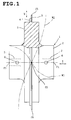
- Figs. 1 to 3 show an embodiment of the present invention.
- Fig. 1 shows the structure of an ultrasonic vibration cutting tool 1
- Fig. 2 shows the method of producing the ultrasonic vibration cutting tool 1
- Fig. 3 shows a structure for connecting the ultrasonic vibration cutting tool 1
- a booster 11 and a transducer 15 shows ultrasonic vibration cutting.
- the ultrasonic vibration cutting tool 1 comprises a resonator 2, a vibration conversion portion 3, a ring-shaped projection 4, a blade 5, tool mating portions 6, threaded holes 7 and the like.
- the resonator 2 is made from aluminum which is one of materials having excellent acoustic characteristics and has a length equal to the half of the wavelength of resonance frequency of ultrasonic vibration input from one end thereof.
- the maximum vibration amplitude points fl and f3 of a vibration waveform W1 showing the instantaneous displacement (vibration amplitude) of ultrasonic vibration in an axial direction shown by an arrow X are existent at the both ends of the resonator 2 and the minimum vibration amplitude point f2 of the vibration waveform W1 is existent at the center of the resonator 2.
- the vibration conversion portion 3 is shaped like a ring which projects outward from the peripheral surface of the resonator 2 at the minimum vibration amplitude point f2 of the vibration waveform W1 in such a manner that it is coaxial to the resonator 2.
- the vibration conversion portion 3 has a diameter larger than that of the resonator 2 and a width in an axial direction with the minimum vibration amplitude point f2 as the center and converts the transmission direction of vibration from an axial direction to a radial direction shown by an arrow Y.
- the instantaneous displacement (vibration amplitude) of ultrasonic vibration whose transmission direction has been converted to a radial direction is a vibration waveform W2.
- the maximum vibration amplitude points f4 and f5 of the vibration waveform W2 are existent on the peripheral side of the vibration conversion portion 3.
- the ring-shaped projection 4 is shaped like a ring which projects outward from the peripheral surface of the vibration conversion portion 3 in such a manner that it is coaxial to the resonator 2.
- the ring-shaped projection 4 is dislocated from the position of the minimum vibration amplitude point f2 toward one side in an axial direction and has an outer diameter smaller than the outer diameter of the blade 5.
- the blade 5 is essentially composed of diamond, is provided at the minimum vibration amplitude point f2 and has a diameter larger than the vibration conversion portion 3.
- the peripheral surface of the blade 5 vibrates in a radial direction shown by the arrow Y. The vibration of the peripheral surface of the blade 5 in a radial direction is determined by the amount of projection from the vibration conversion portion 3.
- the diameter of the blade 5 is set to a range that the edge of the blade 5 vibrates only in a direction shown by the arrow Y based on the diameter of the vibration conversion portion 3.
- the tool mating portions 6 are provided on the peripheral surface of the resonator 2 at positions where they do not interfere with the vibration conversion portion 3.
- the threaded holes 7 are formed in the interior side of the resonator 2 from the centers of the both end surfaces of the resonator 2.
- the initial shape of the resonator 2 made from aluminum is first formed.
- the resonator 2 having this initial shape comprises the vibration conversion portion 3, ring-shaped projection 4, tool mating portions 6, threaded holes 7 and the like except the blade 5.
- the resonator 2 excluding the ring-shaped projection 4, that is, the resonator 2, vibration conversion portion 3, tool mating portions 6, threaded holes 7 and the like are marked with a masking member 10.
- the masked portions shown in Fig. 2(b) are placed in a plating tank 31 to grow the diamond blade 5 on the peripheral surface of the vibration conversion portion 3 with the ring-shaped projection 4 as a seed.
- the plating tank 31 is filled with a plating solution 32 prepared by mixing a nickel sulfate solution and diamond powders, the positive electrode 33 of a power source for plating is connected to a portion other than the blade growing portion of the ring-shaped projection 4, and the negative electrode 34 of the power source for plating is connected to the plating tank 31.
- the diamond powders contained in the plating solution 32 are grown on the peripheral surface of the vibration conversion portion 3 by this electrolytic plating method with the ring-shaped projection 4 as a seed as shown in Fig. 2(d) to form the blade 5 essentially composed of diamond, and the masking member 10 is removed.
- This grown blade 5 is located at the minimum vibration amplitude point f2 shown in Fig. 3 and its thickness is several microns to 200 microns, for example.
- the peripheral portion 4a of the ring-shaped projection 4 is removed by aluminum etching so that the outer diameter of the ring-shaped projection 4 is set smaller than the outer diameter of the blade 5, and an ultrasonic vibration cutting tool 1 comprising the resonator 2 and the blade 5 which are integrated with each other as shown in Fig. 1 is obtained.
- a booster 11 is connected to one end of the resonator 2 by a headless screw 16, and a transducer 15 is connected to the other end of the booster 11 by a headless screw 17.
- the booster 11 is made from a material having excellent acoustic characteristics such as titanium, aluminum or hardened iron and has a length equal to the wavelength of resonance frequency of ultrasonic vibration transmitted from the transducer 15.
- the maximum vibration amplitude points fll and fl5 of the vibration waveform W1 are existent at both end portions of the booster 11.
- the booster 11 comprises front and rear support portions 12 and tool mating portions 13.
- Each of the support portions 12 is shaped like a crank consisting of a thick root portion 12a, a thin portion 12b and a thick portion 12c.
- the root portion 12a is shaped like a ring which projects outward from the peripheral surface of the booster 11 in a radial direction at the minimum vibration amplitude point f12 or f14 of the booster 11.
- the thin portion 12b is shaped like a cylinder which projects in a direction parallel to an axial direction from the fringe of the root portion 12a.
- the thick portion 12c is shaped like a ring which projects outward in a radial direction from the end of the thin portion 12b.
- the crank shapes of the support portions 12 are bisymmetric to each other but may face the same direction.
- the tool mating portions 13 are provided on the peripheral surface of the booster 11 at positions where they do not interfere with the support portions 12.
- the booster 11 and the transducer 15 shown in Fig. 3 are installed in the ultrasonic vibration rotation unit 21 of an ultrasonic vibration cutting apparatus 20 in such a manner that they are coaxial to the ultrasonic vibration rotation unit 21, the front and rear support portions 12 shown in Fig. 3 of the booster 11 are fitted in the ultrasonic vibration rotary unit 21, and the vibration conversion portion 3, blade 5 and ring-shaped projection 4 shown in Fig. 1 of the ultrasonic vibration cutting tool 1 are located outside the ultrasonic vibration rotary unit 21.
- the semiconductor wafer 23 incorporating ICs as a member to be cut is fixed on the mounting table 22 of the ultrasonic vibration cutting apparatus 20.
- the controller 24 instructs the CCD camera 25 of the ultrasonic vibration cutting apparatus 20 to start photographing.
- the CCD camera 25 outputs an image signal of the semiconductor wafer 23 on the mounting table 22 to the controller 24, the controller 24 outputs dislocation which is a computation result based on the image signal and reference image information to the mounting table 22 to activate the control function of the mounting table 22, thereby completing the positioning of the semiconductor wafer 23 relative to the ultrasonic vibration rotation unit 21.
- the controller 24 controls the ultrasonic vibration rotation unit 21 and the three-axis drive unit 26 of the mounting table 22, and the blade 5 rotates in one direction and draws a square locus by its linear movement in longitudinal, transverse and vertical directions while it resonates with ultrasonic vibration.
- the blade 5 cuts the semiconductor wafer 23 in one direction once by drawing one square locus.
- the semiconductor wafer 23 is cut into a plurality of belt-like pieces by repeating the movement of the three-axis drive unit 26 along the square locus.
- the controller 24 instructs the mounting table 22 to rotate at 90° by activating the control function of the mounting table 22, thereby changing the angle of the semiconductor wafer 23 with respect to the ultrasonic vibration rotation unit 21 by 90°.
- the controller 24 resumes the control of the 3-axis drive unit 26 to enable the blade 5 to further cut the belt-like pieces of the semiconductor wafer 23 into a plurality of dices, thereby completing the cutting work of one semiconductor wafer 23 by ultrasonic vibration rotation.
- the blade 5 is cooled by the cooling system 28 of the ultrasonic vibration cutting apparatus 20.
- the semiconductor wafer is used as a member to be cut.
- the member to be cut may be a sticky and soft member made from gold, silver, aluminum, solder or copper, a hard and fragile member made from ceramic, silicon or ferrite, or a laminate structure consisting of a synthetic resin and a metal, or a laminate structure consisting of an inorganic material, metal and synthetic resin.
- the ring-shaped projection 4 and the blade are located at the minimum vibration amplitude point f2.
- the ring-shaped projection 4 and the blade may be dislocated from the minimum vibration amplitude point f2 if they are on the peripheral surface in an axial direction of the vibration conversion portion 3. The reason for this is that the vibration amplitude of ultrasonic vibration converted to a radial direction shown by the vibration waveform W2 is the same at any portion of the peripheral surface of the vibration conversion portion 3.
Landscapes
- Engineering & Computer Science (AREA)
- Mechanical Engineering (AREA)
- Grinding And Polishing Of Tertiary Curved Surfaces And Surfaces With Complex Shapes (AREA)
- Polishing Bodies And Polishing Tools (AREA)
- Electroplating Methods And Accessories (AREA)
- Processing Of Stones Or Stones Resemblance Materials (AREA)
- Apparatuses For Generation Of Mechanical Vibrations (AREA)
Abstract
Description
Claims (3)
- An ultrasonic vibration cutting tool comprising a ring-shaped projection (4) and a blade (5) essentially composed of diamond and held by the ring-shaped projection (4) both of which are formed on the peripheral surface of a vibration conversion portion (3) provided on a resonator (2), the outer diameter of the blade (5) being set larger than the outer diameter of the ring-shaped projection (4).
- A method of producing an ultrasonic vibration cutting tool comprising the steps of:immersing a resonator (2) having a vibration conversion portion (3) and a ring-shaped projection (4) in a plating solution (32) containing diamond powders; andgrowing a blade (5) essentially composed of diamond with the ring-shaped projection (4) as a seed by electroplating.
- The method of producing an ultrasonic vibration cutting tool according to claim 2, wherein a peripheral portion of the ring-shaped projection (4) is removed after the growth of hte blade (5) so that the ring-shaped projection (4) is located inside a peripheral portion of the blade (5).
Applications Claiming Priority (2)
| Application Number | Priority Date | Filing Date | Title |
|---|---|---|---|
| JP35083799A JP3469516B2 (en) | 1999-12-09 | 1999-12-09 | Ultrasonic vibration cutting tool and manufacturing method thereof |
| JP35083799 | 1999-12-09 |
Publications (2)
| Publication Number | Publication Date |
|---|---|
| EP1108494A2 true EP1108494A2 (en) | 2001-06-20 |
| EP1108494A3 EP1108494A3 (en) | 2002-12-04 |
Family
ID=18413229
Family Applications (1)
| Application Number | Title | Priority Date | Filing Date |
|---|---|---|---|
| EP00126633A Ceased EP1108494A3 (en) | 1999-12-09 | 2000-12-04 | Ultrasonic vibration cutting tool and production method thereof |
Country Status (7)
| Country | Link |
|---|---|
| US (2) | US6497164B1 (en) |
| EP (1) | EP1108494A3 (en) |
| JP (1) | JP3469516B2 (en) |
| KR (1) | KR100416731B1 (en) |
| CN (1) | CN1305640C (en) |
| CA (1) | CA2327563A1 (en) |
| TW (1) | TW506873B (en) |
Cited By (3)
| Publication number | Priority date | Publication date | Assignee | Title |
|---|---|---|---|---|
| EP1658938A1 (en) * | 2004-11-19 | 2006-05-24 | Sinaptec | Ultrasonic cutting tool and cutting device comprising said cutting tool |
| EP1849569A2 (en) | 2006-04-26 | 2007-10-31 | Herrmann Ultraschalltechnik GmbH & Co. KG | Device for machining workpieces using ultrasound and method for operating such a device |
| EP4567907A1 (en) * | 2023-12-06 | 2025-06-11 | CUSTOMCELLS Holding GmbH | Methods for manufacturing a component for an energy storage device and devices therefor |
Families Citing this family (15)
| Publication number | Priority date | Publication date | Assignee | Title |
|---|---|---|---|---|
| JP2002113666A (en) * | 2000-10-10 | 2002-04-16 | Funasoo Kk | Hand saw capable of cutting glass bottle and method of manufacturing the same |
| JP3898972B2 (en) * | 2002-04-08 | 2007-03-28 | 内山工業株式会社 | Forming method of cylindrical encoder |
| US20060032332A1 (en) * | 2003-03-13 | 2006-02-16 | Kazumasa Ohnishi | Cutting tool and cutting machine |
| WO2006126298A1 (en) * | 2005-05-23 | 2006-11-30 | Kazumasa Ohnishi | Cutting device with disk-like cutting blade |
| US20100212470A1 (en) * | 2006-10-17 | 2010-08-26 | Kazumasa Ohnishi | Disklike cutting tool and cutting device |
| JP2008142798A (en) * | 2006-12-06 | 2008-06-26 | Arutekusu:Kk | Ultrasonic vibration cutting tool |
| JP5139720B2 (en) * | 2007-06-05 | 2013-02-06 | 株式会社ディスコ | Cutting equipment |
| CN103934732B (en) * | 2014-05-13 | 2016-03-30 | 航天科工哈尔滨风华有限公司 | The rotary ultrasonic grinding processing method of alumina ceramic material tape spool thin-walled convex spherical structure |
| DE102016217251A1 (en) * | 2016-09-09 | 2018-03-15 | Sauer Gmbh | A method for machining a workpiece made of hard metal for the production of a tool body on a numerically controlled machine tool with tool-carrying work spindle |
| CA3027620A1 (en) * | 2018-12-13 | 2020-06-13 | Hydro-Quebec | Cutting of soft metals by ultrasonic assistance |
| US12343894B2 (en) * | 2020-02-17 | 2025-07-01 | Corning Incorporated | Vibratory cutting apparatus and method comprising fluid bearings |
| CN113146370B (en) * | 2021-04-13 | 2022-08-05 | 南京航空航天大学 | One-way ultrasonic auxiliary forming grinding equipment and operation method |
| CN114146889B (en) * | 2021-11-15 | 2023-03-24 | 浙江师范大学 | Dual excitation longitudinal-radial mode conversion high-power ultrasonic vibration system |
| JP7756434B2 (en) * | 2022-11-11 | 2025-10-20 | 株式会社アルテクス | Cutting device and cutting method |
| CN121156470B (en) * | 2025-11-19 | 2026-03-10 | 中国工程物理研究院流体物理研究所 | Copper welding method based on wave-absorbing material film metallization |
Family Cites Families (12)
| Publication number | Priority date | Publication date | Assignee | Title |
|---|---|---|---|---|
| US3691707A (en) * | 1969-11-12 | 1972-09-19 | Sola Basic Ind | Semiconductor material cutting apparatus and method of making the same |
| US4180048A (en) * | 1978-06-12 | 1979-12-25 | Regan Barrie F | Cutting wheel |
| JPS61226269A (en) * | 1985-03-29 | 1986-10-08 | Matsutani Seisakusho:Kk | Abrasive grain sticking method |
| US4787362A (en) * | 1986-10-20 | 1988-11-29 | Thermocarbon, Inc. | Abrasive blade having a polycrystalline ceramic core |
| DE3862474D1 (en) * | 1987-02-04 | 1991-05-29 | Taga Electric Co Ltd | ULTRASONIC CUTTER. |
| JPH0277593A (en) * | 1988-09-13 | 1990-03-16 | Asahi Daiyamondo Kogyo Kk | Manufacturing method for thin-edged blades |
| JPH04164559A (en) * | 1990-10-25 | 1992-06-10 | Brother Ind Ltd | Ultrasonic drilling tool |
| US5316559A (en) * | 1991-12-18 | 1994-05-31 | St. Florian Company | Dicing blade composition |
| US5259149A (en) * | 1991-12-18 | 1993-11-09 | St. Florian Company | Dicing blade hub and method |
| FR2735412B1 (en) * | 1995-06-19 | 1997-08-22 | Unir Ultra Propre Nutrition In | ULTRASONIC CUTTING DEVICE |
| JP3128508B2 (en) * | 1996-04-12 | 2001-01-29 | 株式会社アルテクス | Ultrasonic vibration cutter |
| JP3469488B2 (en) | 1999-01-21 | 2003-11-25 | 株式会社アルテクス | Ultrasonic vibration cutting device |
-
1999
- 1999-12-09 JP JP35083799A patent/JP3469516B2/en not_active Expired - Fee Related
-
2000
- 2000-11-28 US US09/722,748 patent/US6497164B1/en not_active Expired - Lifetime
- 2000-12-04 TW TW089125741A patent/TW506873B/en not_active IP Right Cessation
- 2000-12-04 EP EP00126633A patent/EP1108494A3/en not_active Ceased
- 2000-12-05 CA CA002327563A patent/CA2327563A1/en not_active Abandoned
- 2000-12-06 KR KR10-2000-0073682A patent/KR100416731B1/en not_active Expired - Fee Related
- 2000-12-08 CN CNB001349694A patent/CN1305640C/en not_active Expired - Fee Related
-
2002
- 2002-10-08 US US10/265,721 patent/US20030029275A1/en not_active Abandoned
Cited By (4)
| Publication number | Priority date | Publication date | Assignee | Title |
|---|---|---|---|---|
| EP1658938A1 (en) * | 2004-11-19 | 2006-05-24 | Sinaptec | Ultrasonic cutting tool and cutting device comprising said cutting tool |
| FR2878180A1 (en) * | 2004-11-19 | 2006-05-26 | Sinaptec Sa | CUTTING TOOL AND ULTRASONIC CUTTING DEVICE EQUIPPED WITH SAID CUTTING TOOL |
| EP1849569A2 (en) | 2006-04-26 | 2007-10-31 | Herrmann Ultraschalltechnik GmbH & Co. KG | Device for machining workpieces using ultrasound and method for operating such a device |
| EP4567907A1 (en) * | 2023-12-06 | 2025-06-11 | CUSTOMCELLS Holding GmbH | Methods for manufacturing a component for an energy storage device and devices therefor |
Also Published As
| Publication number | Publication date |
|---|---|
| US6497164B1 (en) | 2002-12-24 |
| JP2001162493A (en) | 2001-06-19 |
| CA2327563A1 (en) | 2001-06-09 |
| CN1305640C (en) | 2007-03-21 |
| TW506873B (en) | 2002-10-21 |
| CN1298781A (en) | 2001-06-13 |
| US20030029275A1 (en) | 2003-02-13 |
| KR100416731B1 (en) | 2004-01-31 |
| JP3469516B2 (en) | 2003-11-25 |
| EP1108494A3 (en) | 2002-12-04 |
| KR20010062157A (en) | 2001-07-07 |
Similar Documents
| Publication | Publication Date | Title |
|---|---|---|
| US6497164B1 (en) | Ultrasonic vibration cutting tool and production method thereof | |
| JP3128508B2 (en) | Ultrasonic vibration cutter | |
| EP1925397B1 (en) | Method of and apparatus for working structure | |
| US11446771B2 (en) | Method for producing wafers using ultrasound | |
| KR20180094785A (en) | Method for producing wafer | |
| CN109332820A (en) | A kind of ultrasonic vibration machining gear tooth surface topography machining and control method | |
| JPH0230495A (en) | Method and device for cutting article | |
| JP3772162B2 (en) | Method for manufacturing ultrasonic vibration cutting tool | |
| CN102275231B (en) | Three-dimensional ultrasonic vibration machining working head | |
| JP2005014186A (en) | Ultrasonic vibration cutting tool and manufacturing method thereof | |
| JP2003285297A (en) | Ultrasonic vibration cutting tool and manufacturing method thereof | |
| JP2002301601A (en) | Processing device and processing method | |
| JP2007111803A (en) | Ultrasonic vibration cutting equipment | |
| KR20020072928A (en) | Automatic Polishing Apparatus for Mold using ultrasonic waves vibrating tool | |
| JPH03232575A (en) | Composite vibration driving method of ultrasonic vibrator | |
| CN112420505A (en) | A method for determining the optimal scribing direction of substrate materials | |
| JPH07108401A (en) | Vibration cutting unit using ultrasonic torsional vibration | |
| CN110270488A (en) | Clamping device and pretreating device | |
| JP2005288351A (en) | Ultrasonic compound vibrator and forming method of ultrasonic compound vibrator | |
| KR100483681B1 (en) | a manufacturing process for a material of diamond cutter | |
| JP2006339431A (en) | Nitride semiconductor substrate processing method | |
| JP3073230B2 (en) | Method and apparatus for separating an etched product from a substrate | |
| JPH09216195A (en) | Knife holder for ultrasonic cutter | |
| JP2006326705A (en) | Cutting tools | |
| JPH03234498A (en) | Composite vibrating ultrasonic cutter |
Legal Events
| Date | Code | Title | Description |
|---|---|---|---|
| PUAI | Public reference made under article 153(3) epc to a published international application that has entered the european phase |
Free format text: ORIGINAL CODE: 0009012 |
|
| AK | Designated contracting states |
Kind code of ref document: A2 Designated state(s): AT BE CH CY DE DK ES FI FR GB GR IE IT LI LU MC NL PT SE TR |
|
| AX | Request for extension of the european patent |
Free format text: AL;LT;LV;MK;RO;SI |
|
| PUAL | Search report despatched |
Free format text: ORIGINAL CODE: 0009013 |
|
| AK | Designated contracting states |
Kind code of ref document: A3 Designated state(s): AT BE CH CY DE DK ES FI FR GB GR IE IT LI LU MC NL PT SE TR |
|
| AX | Request for extension of the european patent |
Free format text: AL;LT;LV;MK;RO;SI |
|
| RIC1 | Information provided on ipc code assigned before grant |
Free format text: 7B 23K 20/10 A, 7B 26D 7/08 B, 7B 24D 18/00 B |
|
| 17P | Request for examination filed |
Effective date: 20030224 |
|
| AKX | Designation fees paid |
Designated state(s): DE FR GB |
|
| 17Q | First examination report despatched |
Effective date: 20030728 |
|
| STAA | Information on the status of an ep patent application or granted ep patent |
Free format text: STATUS: THE APPLICATION HAS BEEN REFUSED |
|
| 18R | Application refused |
Effective date: 20040418 |