EP0277823B1 - Ultrasonic vibration cutting device - Google Patents
Ultrasonic vibration cutting device Download PDFInfo
- Publication number
- EP0277823B1 EP0277823B1 EP88300903A EP88300903A EP0277823B1 EP 0277823 B1 EP0277823 B1 EP 0277823B1 EP 88300903 A EP88300903 A EP 88300903A EP 88300903 A EP88300903 A EP 88300903A EP 0277823 B1 EP0277823 B1 EP 0277823B1
- Authority
- EP
- European Patent Office
- Prior art keywords
- flexible vibrator
- tool
- vibrator
- vibration
- flexible
- Prior art date
- Legal status (The legal status is an assumption and is not a legal conclusion. Google has not performed a legal analysis and makes no representation as to the accuracy of the status listed.)
- Expired - Lifetime
Links
- 238000001514 detection method Methods 0.000 claims description 14
- 238000004804 winding Methods 0.000 claims description 14
- 239000000126 substance Substances 0.000 claims description 12
- 229910052751 metal Inorganic materials 0.000 claims description 10
- 239000002184 metal Substances 0.000 claims description 10
- 230000010287 polarization Effects 0.000 claims description 8
- 238000009413 insulation Methods 0.000 claims description 6
- 238000006073 displacement reaction Methods 0.000 description 10
- 230000004048 modification Effects 0.000 description 10
- 238000012986 modification Methods 0.000 description 10
- 230000000694 effects Effects 0.000 description 9
- 230000003247 decreasing effect Effects 0.000 description 5
- 238000002474 experimental method Methods 0.000 description 5
- BQCADISMDOOEFD-UHFFFAOYSA-N Silver Chemical compound [Ag] BQCADISMDOOEFD-UHFFFAOYSA-N 0.000 description 2
- 229910000831 Steel Inorganic materials 0.000 description 2
- 230000002159 abnormal effect Effects 0.000 description 2
- 238000005219 brazing Methods 0.000 description 2
- 238000010586 diagram Methods 0.000 description 2
- 230000005284 excitation Effects 0.000 description 2
- 229910052709 silver Inorganic materials 0.000 description 2
- 239000004332 silver Substances 0.000 description 2
- 239000010959 steel Substances 0.000 description 2
- 238000005452 bending Methods 0.000 description 1
- 238000006243 chemical reaction Methods 0.000 description 1
- 239000002131 composite material Substances 0.000 description 1
- 230000005484 gravity Effects 0.000 description 1
- 239000007788 liquid Substances 0.000 description 1
- 238000000034 method Methods 0.000 description 1
Images


Classifications
-
- B—PERFORMING OPERATIONS; TRANSPORTING
- B23—MACHINE TOOLS; METAL-WORKING NOT OTHERWISE PROVIDED FOR
- B23H—WORKING OF METAL BY THE ACTION OF A HIGH CONCENTRATION OF ELECTRIC CURRENT ON A WORKPIECE USING AN ELECTRODE WHICH TAKES THE PLACE OF A TOOL; SUCH WORKING COMBINED WITH OTHER FORMS OF WORKING OF METAL
- B23H7/00—Processes or apparatus applicable to both electrical discharge machining and electrochemical machining
- B23H7/38—Influencing metal working by using specially adapted means not directly involved in the removal of metal, e.g. ultrasonic waves, magnetic fields or laser irradiation
-
- B—PERFORMING OPERATIONS; TRANSPORTING
- B23—MACHINE TOOLS; METAL-WORKING NOT OTHERWISE PROVIDED FOR
- B23B—TURNING; BORING
- B23B29/00—Holders for non-rotary cutting tools; Boring bars or boring heads; Accessories for tool holders
- B23B29/04—Tool holders for a single cutting tool
- B23B29/12—Special arrangements on tool holders
- B23B29/125—Vibratory toolholders
-
- B—PERFORMING OPERATIONS; TRANSPORTING
- B23—MACHINE TOOLS; METAL-WORKING NOT OTHERWISE PROVIDED FOR
- B23B—TURNING; BORING
- B23B1/00—Methods for turning or working essentially requiring the use of turning-machines; Use of auxiliary equipment in connection with such methods
-
- Y—GENERAL TAGGING OF NEW TECHNOLOGICAL DEVELOPMENTS; GENERAL TAGGING OF CROSS-SECTIONAL TECHNOLOGIES SPANNING OVER SEVERAL SECTIONS OF THE IPC; TECHNICAL SUBJECTS COVERED BY FORMER USPC CROSS-REFERENCE ART COLLECTIONS [XRACs] AND DIGESTS
- Y10—TECHNICAL SUBJECTS COVERED BY FORMER USPC
- Y10S—TECHNICAL SUBJECTS COVERED BY FORMER USPC CROSS-REFERENCE ART COLLECTIONS [XRACs] AND DIGESTS
- Y10S82/00—Turning
- Y10S82/904—Vibrating method or tool
-
- Y—GENERAL TAGGING OF NEW TECHNOLOGICAL DEVELOPMENTS; GENERAL TAGGING OF CROSS-SECTIONAL TECHNOLOGIES SPANNING OVER SEVERAL SECTIONS OF THE IPC; TECHNICAL SUBJECTS COVERED BY FORMER USPC CROSS-REFERENCE ART COLLECTIONS [XRACs] AND DIGESTS
- Y10—TECHNICAL SUBJECTS COVERED BY FORMER USPC
- Y10T—TECHNICAL SUBJECTS COVERED BY FORMER US CLASSIFICATION
- Y10T82/00—Turning
- Y10T82/25—Lathe
- Y10T82/2585—Tool rest
- Y10T82/2589—Quick release tool or holder clamp
Definitions
- the present invention relates to ultrasonic working devices utilizing ultrasonic vibration, particularly ultrasonic vibration cutting devices such as a lathe, a shaper, a planer, and more specifically to a ultrasonic vibration cutting device utilizing flexible vibration as ultrasonic vibration.
- Vibration cutting devices utilizing ultrasonic vibration are known well in the prior art. For example, if a tool shank in a lathe is vibrated in flexible vibration and a tool attached to top end of the tool shank is subjected to ultrasonic vibration in tangential direction of a work for cutting thereby working is performed, cutting resistance is significantly decreased and the working accuracy is improved thus large effects can be obtained.
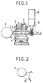
- FIG. 1 shows such a cutting device as an example in the prior art, see US-A-3732665.
- a pushing plate 2 On a tool post 1, a pushing plate 2, a tightening bolt 3, a tightening jig 4 and a tool shank (tool holder) 5 to perform bending (flexible) vibration by these are supported.
- the tightening jig 4 is set to be positioned to node portion of the tool shank 5.
- a cutting tool 7 as tool facing a work 6 is fixed to one top end of the tool shank 5.
- a vertical vibrator 8 and an amplitude enlarging horn 9 are contacted at other end side of the tool shank 5, and positioned to loop portion of vibration mode (shown by dash-and-dot line) of the tool shank 5.
- the vertical vibrator 8 is driven by a ultrasonic oscillator (not shown)
- the tool shank 5 is vibrated as in dash-and-dot line shown and top end of the cutting tool 7 is subjected to ultrasonic vibration in the cutting direction thereby the vibration cutting effects as above described can be exhibited.
- the cutting speed of the work 6 is made v
- vibration frequency of the cutting tool 7 vibrating is made f
- amplitude is made a
- the vertical vibrator 8 as generating source of ultrasonic vibration can be mounted on position remote from the cutting tool 7, the device can be easily installed to a general-purpose lathe and therefore is advantageous.
- transducer is disclosed in US-A-3 772 538 and this relies on use of two adjacent discs in order to produce a vibratory output longitudinally of the transducer assembly. This does not result in any significant vibration at right angles to the assembly, nor is the energy very concentrated.
- a first object of the invention is to provide an ultrasonic vibration cutting device which overcomes the problem of the described prior art.
- a further objective is to provide an ultrasonic vibration cutting device which is compact and enables a controlled vibration at right angles to the longitudinal axis to be achieved.
- an ultrasonic vibration cutting device comprising: a flexible vibrator having a longitudinal axis and formed by tightening metal substances integrally using a tightening tool on both surfaces of one or more electrostrictive elements and a cutting tool installed on one output portion of the flexible vibrator, the electrostrictive elements being polarised in their thickness direction, being divided uniformly in two sections in a direction transverse to the thickness direction, and being located on the longitudinal axis parallel to the thickness direction, whereby exciting voltages of selected phase may be applied to the two sections in oder to provide a vibration on the cutting tool on the output portion in a direction transverse to the longitudinal axis.
- FIGS. 3 through 11 A first embodiment of the invention will be described referring to FIGS. 3 through 11.
- a flexible vibrator 10 is installed, and enclosed and supported, for example, in a holder 11 formed upward in U-like form.
- Such flexible vibrator 10 is equivalent, for example, to that disclosed in JP-A-62 114478 by the present applicant.
- JP-A-62114478 is published after the priority date of the present application.
- a ring-shaped electrostrictive element body 12 polarized in thickness direction is installed on one surface of the electrostrictive element body 12.
- electrodes 14, 15 are formed in dividing in two about an insulation portion 13, and on other surface thereof, a common electrode 16 is formed as a whole electrode thus an electrostrictive element 17 is constituted by these.
- two electrostrictive elements 17 in such constitution are prepared and the insulation portions 13 are registered, and two electrode plates 18, 19 in U-like form as shown in FIG. 8 are interposed, and the electrodes 14, 15 are opposed and an insulation cylinder 20 is inserted in center portion.
- an output end portion 21 is made thin, and a metal substance 23 with an exponential step portion 22 to form a horn for vibration amplitude enlarging is contacted.
- a common electrode plate 24 is contacted and a metal substance 25 is contacted with the common electrode plate 24.
- the metal substance 25 is provided with a hole 27 for inserting the bolt 26, and the metal substance 23 is provided with a threaded portion 28 for threaded engagement of the bolt 26.
- the flexible vibrator 10 in composite vibrator structure used in the embodiment is constituted.
- a drive control circuit as hereinafter described is connected to such flexible vibrator 10 through the electrodes 14, 15, the common electrode 16, the electrode plates 18, 19 and the common electrode plate 24, and the flexible vibrator 10 is excited and driven by the drive control circuit.
- the drive power source which can be controlled in independent phases from each other is connected to the electrode plates 18, 19 and the common electrode plate 24, and the drive frequency is adjusted to the axial resonance frequency.
- the phase difference is made zero, same phase parallel drive is performed, and the output end portion 21 becomes the axial resonance vibration and is vibrated in similar vibration mode to that of the vertical vibrator.
- phase of drive voltage to be applied to other electrode 19 with respect to one electrode 18 is inverted, i.e., if voltage of reverse phase is applied, the output end portion 21 is bent in perpendicular direction to the axis and in dividing direction of the electrostrictive element 17 (i.e., in vertical direction shown in FIG. 6), and performs resonance vibration.
- each of the electrodes 14, 15 may be supplied with reverse polarization directions from each other in the thicknes direction. In this case, voltage of the same phase is applied to the two electrode plates 18, 19, thereby flexible vibration is generated in the output end portion 21.
- the electrostrictive element 17 may be separated and of semicircular ring-shaped element structure; and the polarization direction may be the same direction or reverse direction.
- the flexible vibrator 10 in such structure is schematically shown in FIGS. 3 through 5.
- characteristics A in FIG. 4(b) such flexible vibrator 10 is constituted to perform flexible resonance in one wave length on the axial line.
- the flexible vibrator 10 is provided with conical recesses 29 formed on four node positions N1, N2, N1′, N2′ at both lateral sides.
- the flexible vibrator 10 from the output end portion 21 to the first node positions N1, N1′ is made thin including the exponential step portion 22 so that the flexible vibration displacement at the output end portion 21 is enlarged.
- the embodiment is characterized in that the cutting tool 33 as tool to perform cutting of the work 32 is installed directly to the output end portion 21 of the flexible vibrator 10.
- the structure is quite simple and the vertical vibrator as in the ultrasonic vibration cutting device in the prior art becomes unnecessary. Thereby the structure is simplified and the workability is improved. Further, the vibration amplitude enlarging ratio is increased, and the total length may be small in comparison to the vibration system in the prior art thereby the device is made small and compact.
- FIG. 4(c) shows instantaneous vibration displacement distribution viewing from side of the flexible vibrator 10 in amount and direction of each arrow B, and the distribution in FIG. 4(c) corresponds to characteristics A of the flexible vibration displacement distribution on the axial direction shown in FIG. 4(b). L designates the loop position. As understood also from each arrow B in FIG.
- the drive system of the flexible vibrator 10 may be constituted as shown in FIG. 9.
- direction of residual polarization is shown by arrow in each of the electrostrictive elements 17a, 17b divided in two by the insulation portion 13.
- the electrode plates 18, 19 are connected to both ends of a secondary winding 35 of an output transformer 34.
- a center tap 36 of the secondary winding 35 is grounded through a detection resistor R s .
- a drive power source 38 is connected to both ends of a primary winding 37 of the output transformer 34, and one end of the drive power source 38 is grounded. Also the common electrode plate 24 is grounded.
- the vibration direction of the cutting tool 33 is tangential direction to the work 33, and as described referring to FIG. 2, if the back component force in the axial direction is applied to the cutting tool the vibration cutting effect will be eliminated. Consequently, angle of the axial line of the flexible vibrator 10 may be set so that such back component force is not applied to the cutting tool 33. In order to attain this, for example, such back component force is detected, and the back component force may be made zero (Null) at setting the angle of the axial line of the vibrator.
- the angle setting can be performed, for example, by adjustment of mounting angle of the holder 11 to the machine tool.
- signal voltage E s is generated in the detection resistor R s by piezoelectric phenomenon when stress of the same direction is applied simultaneously to both electrostrictive elements 17a, 17b. Since the extending or contracting direction is reverse in both electrostrictive elements 17a, 17b, the signal voltage E s is not detected to the load in the vibration direction component. On the other hand, if the back component force is applied during the cutting working, the signal voltage E s is generated by receiving the force in the axial direction, thereby it is discriminated whether the back component force exists or not.
- the angle setting of the axial line of the flexible vibrator 10 to the work 32 may be performed. If the detection function of the back component force is not required, the detection resistor R s may be omitted and the center tap 36 of the secondary winding 35 of the output transformer 34 may be directly grounded.
- the drive system shown in FIG. 11 may be used. That is, each of the electrode plates 18, 19 is excited by voltage in the same phase as that of the resonance frequency, and connection position of the drive power source and the detection resistor is changed in comparison to FIG. 9. Both ends of a primary winding 40 of a detection transformer 39 are connected to the electrode plates 18, 19, and a drive power source 42 is connected to a center tap 41 of the primary winding 40 and grounded. On the other hand, the detection resistor R s is connected to both ends of a secondary winding 43, and one end thereof is grounded.
- FIG. 12 shows a modification regarding support position by four points of the flexible vibrator 10. That is, the arrangement position of the electrostrictive element 17 is changed so that the electrostrictive element 17 is not disposed in the position of the conical recess 29 being the support position of the flexible vibrator 10. According to such structure, since the electrostrictive element 17 is disposed out of the support positions by four-point contacting, relative position shifting of the node position due to tightening during the vibrator assembling, i.e., shifting of the positon of the conical recess 29, can be prevented.
- flexible vibrator 10 is not limited to circular cross-section, but may be square cross-section for example.
- the number of the electrostrictive elements 17 to be used is not limited to two, but may be one or three or more.
- the cutting tool 33 is detachably installed to the flexible vibrator 10. That is, the cutting tool 33 is not installed directly to the output end portion 21 of the flexible vibrator 10, but a right-handed male screw thread 50 is formed on an outer circumferential surface thereof.
- the cutting tool 33 is fixed to one end by silver brazing method or the like, and a tool holder 52 with a left-handed male screw thread 51 of the same diameter as that of the right-handed male screw thread 50 formed on the outer circumferential surface is installed to other end.
- a spanner setter 53 is formed on a part of the outer circumferential surface of the tool holder 52. Further, a tightening ring 56 as connecting tool is installed, and a right-handed female screw thread 54 and a left-handed female screw thread 55 are formed on an inner circumferential surface of the tightening ring 56, and a spanner setter (not shown) is formed on an outer circumferential surface thereof.
- the right-handed female screw thread 54 of the tightening ring 56 is threadedly engaged with the right-handed male screw thread 50 of the flexible vibrator 10, and the left-handed female screw thread 55 is threadedly engaged with the left-handed male screw thread 52 of the tool holder 52, thereby the flexible vibrator 10 and the tool holder 52 are tightened.
- the spanner setter of the tightening ring 56 serves for the tightening
- the spanner setter 53 of the tool holder 52 serves mainly for the angle registering.
- the cutting tool 33 is detachably installed to the flexible vibrator 10. Consequently, if a plurality of tool holders 52 with various cutting tools 33 fixed thereto are provided, the cutting working by sny sort of the cutting tool 33 can be performed only by changing of the tool holder 52 without removing the flexible vibrator 10 from the holder 11. Also when regrinding of the cutting tool 33 is required, the tool holder 52 is detached from the flexible vibrator 10 and can be used for the working easily and rapidly.
- the flexible vibrator 10 is driven so that characteristics of the vibration displacement distribution becomes characteristics A shown in FIG. 13(b) and FIG. 14(b) for example. That is, the edge of the cutting tool 33 is disposed naturally to the loop position, and also the tightening ring 56 is disposed to the loop position L1. Thereby mass of the tightening ring 56 is added to the loop position L1, which contributes to enlarging of the vibration amplitude of the cutting tool 33. Moreover, since the equivalent mass of the 1/2 wave length resonance region is increased in region from the loop position L1 to the edge of the cutting tool 33, both the vibration speed and the vibration inertia of the cutting tool 33 are increased.
- the flexible vibrator 10 is constituted in that the two electrostrictive elements 17 divided in two of diameter 45 mm and thickness 5 mm are assembled between steel substances with large diameter portion of ⁇ 45 mm and small diameter portion of ⁇ 18 mm.
- the tool holder 52 is constituted in that a superhard cutting tool 33 is contacted in silver brazing to an end portion of a steel substance with large diameter portion of ⁇ 18 mm and small diameter portion of ⁇ 10 mm.
- the tightening ring 56 is a hexagon nut where a right-handed female screw thread and a left-handed female screw thread with M18 are machined on an inner circumference of diagonal 22 mm and length 16 mm.
- FIG. 15 shows an embodiment where the tightening ring 56 is of cap nut structure. That is, only when the tightening ring 56 is threadedly engaged with the flexible vibrator 10, an edge portion 52a formed on the tool holder 52 is pressed to the output end portion 21 of the flexible vibrator 10 by a step portion 56a formed on the inner circumferential surface of the tightening ring 56, thereby the flexible vibrator 10 and the tool holder 52 are fixed. According to such structure, connection between the flexible vibrator 10 and the tool holder 52 can be performed more simply and rapidly.
- FIG. 15 shows an embodiment where the tightening ring 56 is of cap nut structure. That is, only when the tightening ring 56 is threadedly engaged with the flexible vibrator 10, an edge portion 52a formed on the tool holder 52 is pressed to the output end portion 21 of the flexible vibrator 10 by a step portion 56a formed on the inner circumferential surface of the tightening ring 56, thereby the flexible vibrator 10 and the tool holder 52 are fixed. According to
- FIG. 16 shows another modification where a slit 57 is provided on each contact portion between the flexible vibrator 10 and the tool holder 52, and a positioning plate 58 as rotation preventing means is inserted in the slit 57, thereby the flexible vibrator 10 and the tool holder 52 are connected.
- tightening between the flexible vibrator 10 and the tool holder 52 is performed in that the tightening ring 56 is threadedly engaged with the right-handed male screw thread 50 of the flexible vibrator 10 and the left-handed male screw thread 51 of the tool holder 52 as shown in FIG. 16, or in the cap nut structure as shown in FIG. 15.
- Also forming position of the slit 57 is previously set to position so that the tool holder 52 is in the correct mounting direction to the flexible vibrator 10. Consequently in such structure, the positioning of the tool holder 52 during tightening becomes unnecessary.
- the cutting tool 33 is not installed directly to side of the output end portion 21 of the flexible vibrator 10, and therefore this point is common to the second embodiment and the third embodiment. Consequently, the same parts and the equivalent parts to those in the first embodiment and the second embodiment are designated by the same reference numerals, and the description shall be omitted.
- the third embodiment is different from the second embodiment in particulars of mounting structure of the tool holder 52 and characteristics of the vibration displacement distribution of the flexible vibrator 10.
- the right-handed male screw thread 50 is formed on the outer circumferential surface and a slit 60 as rotation preventing means is formed on the end surface.
- the left-handed male screw thread 51 with the same diameter as that of the right-handed male screw thread 50 and in different direction is formed on the outer circumferencial surface, and a plate-shaped projection 61 as rotation preventing means to fit to the slit 60 is projected and formed on the end surface.
- the mounting structure of the tool holder 52 may be the cap nut structure as described referring to FIG. 15.
- the vibration displacement distribution is set so that the standing wave of 1.5 wave length is produced from the rear end of the flexible vibrator 10 to the top end of the cutting tool 33, thereby the connection position between the flexible vibrator 10 and the tool holder 52 is disposed to the node position N3.
- This is the countermeasure in view of the fact that the connection point between the flexible vibrator 10 and the tool holder 52 becomes weak in the strength. That is, the connection point between the flexible vibrator 10 and the tool holder 52 is disposed to the node position N3 where strain stress is not theoretically applied, thereby weakness of the connection point in the strength is compensated.
- FIGS. 18 through 22 This embodiment relates to holding structure of the flexible vibrator 10.
- the flexible vibrator 10 to be used is similar to that described in the second embodiment where the cutting tool 33 is detachably installed. Consequently, the same parts and the equivalent parts to those described in the first embodiment and the second embodiment are designated by the same reference numerals, and the description shall be omitted.
- a ring-shaped body 71 having a setscrew 70 to support the flexible vibrator 10 at the node portion is installed on the outer circumference of the flexible vibrator 10, and is tightened by a housing 72 thereby the flexible vibrator 10 is held. Structure of the flexible vibrator 10, the ring-shaped body 71 and the housing 72 will now be described.
- R step portion 22 as step portion to form a horn portion is formed, and a groove 74 is formed on a surface where the R step portion 22 is formed and an O-ring 73 is inserted along its circumference.
- Structure of the flexible vibrator 10 of the fourth embodiment is different from that described in the second embodiment only in this point.
- the ring-shaped body 71 comprises a cylindrical sleeve 75 with both ends opened, and a ring 76 pushed in the sleeve 75.
- two tapped holes 77 are formed and positioned to the node portion N2 of the vibration of the flexible vibrator 10
- two adjusting holes 78 are formed and positioned to the node portion N3.
- Two tapped holes 79 are formed also at the ring 76 and registered with these adjusting holes 78.
- the setscrews 70 are threadedly engaged with all four tapped holes 77, 79, and top end of each setscrew 70 is locked to the conical recess 29 of the flexible vibrator 10 thereby the flexible vibrator 10 is held in the point contacting.
- a hexagon hole 70a is formed commonly on the head of the setscrew 70.
- a portion of the cutting tool 33 is projected from an opening on one end of the sleeve 75, and a flange 80 at the opening to project the cutting tool 33.
- the flange 80 is positioned so that the flexible vibrator 10 held correctly is pressed through the O-ring 73 made of rubber.
- an insulation cylinder 81 of circular ring form is inserted, in order to protect the sleeve 75 from the plasma effect which may be produced irregularly and instantaneously in the electrostrictive element 17 to which high voltage is applied.
- a cap 82 is tightened by screwing.
- a cable 83 to connect the electrode plates 18, 19 and the common electrode plate 24 to the external circuit is inserted in the cap 82.
- An O-ring 84 is fitted to the cable 83 on outside of the sleeve 75, and is pressed to the cap 82 by a cap nut 85 screwed to the cap 82.
- a groove 76a for inserting the cable 75 is cut on the ring 76 so that connection of the cable 83 to the electrodes 14, 15 and the common electrode 16 is not obstructed.
- the housing 72 is of parallelopipedon form, and a cylindrical cavity 86 to hold the sleeve 75 penetrates from one end to other end of the housing, and a split groove 87 is formed so that the cavity 86 communicates with the upper surface.
- a collar 90 having bolt holes 89 for fixing it using bolts 88 to a workbench 100 such as a tool post, a table or the like is formed.
- two inserting holes 91 are formed in horizontal direction on one thick portion, and tightening tapped holes 92 as tapped holes corresponding to these inserting holes 91 are formed in horizontal direction on other thick portion via the split groove 87.
- a bolt 93 with hexagon hole as tightening body is inserted in each inserting hole 91 and threadedly engaged with each tightening tapped hole 92, and the diameter of the cavity 86 is varied delicately by the tightening condition of these bolts 93 with hexagon hole.
- the flexible vibrator 10 is supported by the setscrews 70 at positions of the node portions N2, N3 of the vibration in the point contacting state.
- the ring-shaped body 71 to support the flexible vibrator 10 is inserted within the cavity 86 in the housing 72, and fixed with uniform and strong force by tightening the bolts 93 with hexagon hole. Consequently, the flexible vibrator 10 can be held with high rigidity against the cutting force, and the loss to the vibration can be decreased and other secondary advantages can be produced.
- the flexible vibrator 10 is held within the sleeve 75 in air tightness by the O-ring 73 made of rubber and the O-ring 84. Consequently, the cutting liquid supplied to the cutting tool 33 during cutting can be securely prevented from leaking into the electrostrictive element 17.
- FIG. 23 shows a modification of the housing 72.
- a tail 94 is provided on a side surface and fitted to a devotail groove (not shown) of a tool post, a table or the like thereby the housing 72 can be fixed at any position and can be moved in vertical direction.
Landscapes
- Engineering & Computer Science (AREA)
- Mechanical Engineering (AREA)
- Physics & Mathematics (AREA)
- Optics & Photonics (AREA)
- Chemical & Material Sciences (AREA)
- Chemical Kinetics & Catalysis (AREA)
- Electrochemistry (AREA)
- Apparatuses For Generation Of Mechanical Vibrations (AREA)
- Turning (AREA)
Description
- The present invention relates to ultrasonic working devices utilizing ultrasonic vibration, particularly ultrasonic vibration cutting devices such as a lathe, a shaper, a planer, and more specifically to a ultrasonic vibration cutting device utilizing flexible vibration as ultrasonic vibration.
- Vibration cutting devices utilizing ultrasonic vibration are known well in the prior art. For example, if a tool shank in a lathe is vibrated in flexible vibration and a tool attached to top end of the tool shank is subjected to ultrasonic vibration in tangential direction of a work for cutting thereby working is performed, cutting resistance is significantly decreased and the working accuracy is improved thus large effects can be obtained.
- FIG. 1 shows such a cutting device as an example in the prior art, see US-A-3732665. On a
tool post 1, a pushingplate 2, a tightening bolt 3, a tightening jig 4 and a tool shank (tool holder) 5 to perform bending (flexible) vibration by these are supported. In this case, the tightening jig 4 is set to be positioned to node portion of thetool shank 5. A cutting tool 7 as tool facing awork 6 is fixed to one top end of thetool shank 5. Avertical vibrator 8 and an amplitude enlarging horn 9 are contacted at other end side of thetool shank 5, and positioned to loop portion of vibration mode (shown by dash-and-dot line) of thetool shank 5. - In the ultrasonic vibration cutting device in such constitution, if the
vertical vibrator 8 is driven by a ultrasonic oscillator (not shown), thetool shank 5 is vibrated as in dash-and-dot line shown and top end of the cutting tool 7 is subjected to ultrasonic vibration in the cutting direction thereby the vibration cutting effects as above described can be exhibited. More specifically, if the cutting speed of thework 6 is made v, vibration frequency of the cutting tool 7 vibrating is made f, and amplitude is made a, the effects can be exhibited under condition that v <2πfa. - According to such structure, since the
vertical vibrator 8 as generating source of ultrasonic vibration can be mounted on position remote from the cutting tool 7, the device can be easily installed to a general-purpose lathe and therefore is advantageous. - Problems in the above-mentioned prior art will be described as follows. At first point, the
vertical vibrator 8 or the enlarging horn 9 may obstruct the working during working state. At second point, the device inevitably becomes large scale because of its structure. At third point, the cutting tool 7 must be exchanged corresponding to use, and during the changing it is difficult that thetool shank 5 is accurately mounted to thetool post 1. Consequently, derivative problems as hereinafter exemplified may occur. When the tightening jig 4 is not accurately disposed to node position of thetool shank 5, energy loss is produced and edge of the cutting tool 7 is out of the correct vibration direction thereby not only the above-mentioned cutting effects are deteriorated but harmful results are produced. Also troublesome labor and careful caution are required in changing of the cutting tool 7. At fourth point, as shown in FIG. 2, at contacts of the cutting tool 7 with thework 6, in addition to main component force Pc in tangential direction of the work, radial direction back component force Pt towards the cutting tool 7 is produced. As a result, resultant force P of these components acts on the cutting tool 7, thereby the harmful and abnormal vibration is produced and sufficient vibration cutting effect cannot be obtained. - Another form of transducer is disclosed in US-A-3 772 538 and this relies on use of two adjacent discs in order to produce a vibratory output longitudinally of the transducer assembly. This does not result in any significant vibration at right angles to the assembly, nor is the energy very concentrated.
- A first object of the invention is to provide an ultrasonic vibration cutting device which overcomes the problem of the described prior art.
- In particular, a further objective is to provide an ultrasonic vibration cutting device which is compact and enables a controlled vibration at right angles to the longitudinal axis to be achieved.
- Accordingly the invention provides an ultrasonic vibration cutting device comprising:
a flexible vibrator having a longitudinal axis and formed by tightening metal substances integrally using a tightening tool on both surfaces of one or more electrostrictive elements and a cutting tool installed on one output portion of the flexible vibrator, the electrostrictive elements being polarised in their thickness direction, being divided uniformly in two sections in a direction transverse to the thickness direction, and being located on the longitudinal axis parallel to the thickness direction, whereby exciting voltages of selected phase may be applied to the two sections in oder to provide a vibration on the cutting tool on the output portion in a direction transverse to the longitudinal axis. - Consequently structure to deteriorate the workability is not produced, and the structure can be simplified and the device as a whole can be made compact. Also in a structure that the flexible vibrator and the cutting tool is assembled or detached using a connecting tool, cutting tools os two sorts or more can be easily changed.
- Brief Description of the Drawings
- FIG. 1 is a side view of a whole device as an example in the prior art;
- FIG. 2 is a side view illustrating directions of force of a cutting tool to a work;
- FIG. 3 is a schematic perspective view of a whole device as a first embodiment of the invention;
- FIG. 4 is a side view illustrating the device including vibration mode;
- FIG. 5 is a plan view of the device;
- FIG. 6 is a longitudinal sectional view illustrating basic structure of a flexible vibrator;
- FIG. 7 is a perspective view of an electrostrictive element;
- FIG. 8 is a perspective view of an electrode plate;
- FIG. 9 is a circuit diagram of a vibration system;
- FIG. 10 is a side view illustrating directions of force of a cutting tool to a work;
- FIG. 11 is a circuit diagram illustrating a modification to the vibration system;
- FIG. 12 is a schematic side view illustrating a modification regarding support position of the flexible vibrator;
- FIG. 13 is a longitudinal sectional view illustrating a second embodiment of the invention;
- FIG. 14 is a side view illustrating by cutaway of connection structure between a flexible vibrator and a cutting tool;
- FIG. 15 is a longitudinal sectional view illustrating a modification of the connection structure between the parts;
- FIG. 16 is an exploded perspective view illustrating another modification of the parts;
- FIG. 17 is a side view illustrating a third embodiment of the invention;
- FIG. 18 is a transverse plan view of a whole device illustrating a fourth embodiment of the invention;
- FIG. 19 is a perspective view of a flexible vibrator;
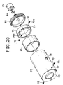
- FIG. 20 is an exploded perspective view of a ring-shaped body and its accessories;
- FIG. 21 is a perspective view of a housing;
- FIG. 22 is a front view partly cutaway of the housing; and
- FIG. 23 is a perspective view illustrating a modification of the housing.
- A first embodiment of the invention will be described referring to FIGS. 3 through 11. As shown in FIGS. 3 through 5, a
flexible vibrator 10 is installed, and enclosed and supported, for example, in aholder 11 formed upward in U-like form. - Now, basic structure and vibration operation of such
flexible vibrator 10 will be described referring to FIGS. 6 through 8. Suchflexible vibrator 10 is equivalent, for example, to that disclosed in JP-A-62 114478 by the present applicant. JP-A-62114478 is published after the priority date of the present application. As shown in FIG. 7, a ring-shapedelectrostrictive element body 12 polarized in thickness direction is installed. On one surface of theelectrostrictive element body 12,electrodes insulation portion 13, and on other surface thereof, acommon electrode 16 is formed as a whole electrode thus anelectrostrictive element 17 is constituted by these. For example, twoelectrostrictive elements 17 in such constitution are prepared and theinsulation portions 13 are registered, and twoelectrode plates electrodes insulation cylinder 20 is inserted in center portion. In oneelectrostrictive element 17 to side of thecommon electrode 16, anoutput end portion 21 is made thin, and ametal substance 23 with anexponential step portion 22 to form a horn for vibration amplitude enlarging is contacted. In otherelectrostrictive element 17 to side of thecommon electrode 16, acommon electrode plate 24 is contacted and ametal substance 25 is contacted with thecommon electrode plate 24. These members are fixed integrally by a bolt as tightening tool. That is, themetal substance 25 is provided with ahole 27 for inserting thebolt 26, and themetal substance 23 is provided with a threadedportion 28 for threaded engagement of thebolt 26. Thus theflexible vibrator 10 in composite vibrator structure used in the embodiment is constituted. - For example, a drive control circuit as hereinafter described is connected to such
flexible vibrator 10 through theelectrodes common electrode 16, theelectrode plates common electrode plate 24, and theflexible vibrator 10 is excited and driven by the drive control circuit. - The drive power source which can be controlled in independent phases from each other is connected to the
electrode plates common electrode plate 24, and the drive frequency is adjusted to the axial resonance frequency. When the phase difference is made zero, same phase parallel drive is performed, and theoutput end portion 21 becomes the axial resonance vibration and is vibrated in similar vibration mode to that of the vertical vibrator. On the contrary, if phase of drive voltage to be applied toother electrode 19 with respect to oneelectrode 18 is inverted, i.e., if voltage of reverse phase is applied, theoutput end portion 21 is bent in perpendicular direction to the axis and in dividing direction of the electrostrictive element 17 (i.e., in vertical direction shown in FIG. 6), and performs resonance vibration. - Operation principle of the
flexible vibrator 10 to be used in the embodiment has been described. Although theelectrostrictive element 17 is ring-shaped and integral, and the polarization direction of residual polarization is thickness direction in the above description, for example, each of theelectrodes electrode plates output end portion 21. Also theelectrostrictive element 17 may be separated and of semicircular ring-shaped element structure; and the polarization direction may be the same direction or reverse direction. - The
flexible vibrator 10 in such structure is schematically shown in FIGS. 3 through 5. For example, as characteristics of vibration displacement distribution are shown as characteristics A in FIG. 4(b), suchflexible vibrator 10 is constituted to perform flexible resonance in one wave length on the axial line. Theflexible vibrator 10 is provided withconical recesses 29 formed on four node positions N₁, N₂, N₁′, N₂′ at both lateral sides. Among them, to the conical recesses 29 on the node positions N₁′, N₂′, two tip end pins 30 fixed to theholder 11 is locked, and to the conical recesses 29 on the node positions N₁, N₂, top ends of twotip end bolts 31 movably installed to theholder 11 are locked, and when thesetip end bolts 31 is tightened theflexible vibrator 10 is fixed and supported by theholder 11 from both lateral sides. That is, theflexible vibrator 10 is supported at the four node positions in the point contacting state. - The
flexible vibrator 10 from theoutput end portion 21 to the first node positions N₁, N₁′ is made thin including theexponential step portion 22 so that the flexible vibration displacement at theoutput end portion 21 is enlarged. The embodiment is characterized in that the cuttingtool 33 as tool to perform cutting of thework 32 is installed directly to theoutput end portion 21 of theflexible vibrator 10. - In the state that the
flexible vibrator 10 with the cuttingtool 33 installed to theoutput end portion 21 is supported by theholder 11, if theflexible vibrator 10 is subjected to flexible vibration, the cuttingtool 33 at theoutput end portion 21 performs the resonance vibration significantly in vertical direction in the sate shown in FIG. 4(a). Consequently, if the top end of thecutting tool 33 is pushed to thework 32 rotating in the arrow direction, the vibration cutting of thework 32 is carried out. - According to the cutting device of the embodiment where the
cutting tool 33 is installed directly to theoutput end portion 21 of theflexible vibrator 10, the structure is quite simple and the vertical vibrator as in the ultrasonic vibration cutting device in the prior art becomes unnecessary. Thereby the structure is simplified and the workability is improved. Further, the vibration amplitude enlarging ratio is increased, and the total length may be small in comparison to the vibration system in the prior art thereby the device is made small and compact. - Since the
flexible vibrator 10 is fixed and held in the point contacting state at the node positions N₁, N₂, N₁′, N₂′ of the flexible vibration, holding of the vibration body (i.e., the flexible vibrator 10) becomes simple and secure. Also according to the point contacting holding, vibration loss becomes little and the drive becomes efficient. The reason will be described referring to FIG. 4(c). FIG. 4(c) shows instantaneous vibration displacement distribution viewing from side of theflexible vibrator 10 in amount and direction of each arrow B, and the distribution in FIG. 4(c) corresponds to characteristics A of the flexible vibration displacement distribution on the axial direction shown in FIG. 4(b). L designates the loop position. As understood also from each arrow B in FIG. 4(c), even at the node positions N₁, N₂, displacement in the axial direction is performed at position remote from the axial line of theflexible vibrator 10, thereby it follows that points at the node positions N₁, N₂ and designated by 1 2 on the center axis only always stand still. That is, in every neighboring node positions N₁, N₂ about thepoints 1 2, direction is changed and displacement is performed in the rotational direction. On account of such condition, if theflexible vibrator 10 is held at thepoints 1 2 as its theoretical still points in the point contacting state, the drive at little vibration loss and good efficiency becomes possible. - When any of the
electrostrictive element 17 in theflexible vibrator 10 is polarized in the same direction as the thickness direction and arranged, the drive system of theflexible vibrator 10 may be constituted as shown in FIG. 9. In FIG. 9, direction of residual polarization is shown by arrow in each of theelectrostrictive elements insulation portion 13. Theelectrode plates output transformer 34. Acenter tap 36 of the secondary winding 35 is grounded through a detection resistor Rs. On the other hand, adrive power source 38 is connected to both ends of a primary winding 37 of theoutput transformer 34, and one end of thedrive power source 38 is grounded. Also thecommon electrode plate 24 is grounded. - In such constitution, if the system is excited from the
drive power source 38 with drive frequency matched to the resonance frequency of theflexible vibrator 10, drive voltage in reverse phase to each other is applied to theelectrode plates electrostrictive element 17a is extended otherelectrostrictive element 17b is contracted, thereby theflexible vibrator 10 generates the resonance vibration. In this state, the cuttingtool 33 installed at theoutput end portion 21 is vibrated significantly in perpendicular direction to the axis (in vertical direction) by the step in the node portion, and if thecutting tool 33 is pushed to thework 32 rotating the cutting working is carried out. - The vibration direction of the
cutting tool 33 is tangential direction to thework 33, and as described referring to FIG. 2, if the back component force in the axial direction is applied to the cutting tool the vibration cutting effect will be eliminated. Consequently, angle of the axial line of theflexible vibrator 10 may be set so that such back component force is not applied to thecutting tool 33. In order to attain this, for example, such back component force is detected, and the back component force may be made zero (Null) at setting the angle of the axial line of the vibrator. The angle setting can be performed, for example, by adjustment of mounting angle of theholder 11 to the machine tool. - Now, detection of the back component force will be described referring to FIG. 9. In FIG. 9, signal voltage Es is generated in the detection resistor Rs by piezoelectric phenomenon when stress of the same direction is applied simultaneously to both
electrostrictive elements electrostrictive elements flexible vibrator 10 to thework 32 may be performed. If the detection function of the back component force is not required, the detection resistor Rs may be omitted and thecenter tap 36 of the secondary winding 35 of theoutput transformer 34 may be directly grounded. - This may be applied also when the vibration direction of the
cutting tool 33 is shifted from the perpendicular direction to the axial direction. That is, as shown in FIG. 10, when the vibration direction of the edge of thecutting tool 33 is shifted from the perpendicular direction to the axial direction, if the vibration direction is not coincident with the direction of the resultant force P including the back component force Pt from thework 32, since the axial component is applied to theflexible vibrator 10, the abnormal state of the vibration direction is found by the signal voltage Es across the detection resistor Rs. In this constitution, including shifting of the vibration direction of thecutting tool 33 from the perpendicular direction to the axial line, coincidence with the direction of reaction of thework 32 is made and therefore the good vibration cutting condition can be set. - As shown in FIG. 11, when the
flexible vibrator 10 has theelectrostrictive elements electrostrictive element 17 as the border, the drive system shown in FIG. 11 may be used. That is, each of theelectrode plates detection transformer 39 are connected to theelectrode plates drive power source 42 is connected to acenter tap 41 of the primary winding 40 and grounded. On the other hand, the detection resistor Rs is connected to both ends of a secondary winding 43, and one end thereof is grounded. - According to this constitution, since excitation output from the
drive power source 42 is applied in the same phase to bothelectrostrictive elements electrostrictive element electrostrictive element electrostrictive elements electrode plates drive power source 42. - FIG. 12 shows a modification regarding support position by four points of the
flexible vibrator 10. That is, the arrangement position of theelectrostrictive element 17 is changed so that theelectrostrictive element 17 is not disposed in the position of theconical recess 29 being the support position of theflexible vibrator 10. According to such structure, since theelectrostrictive element 17 is disposed out of the support positions by four-point contacting, relative position shifting of the node position due to tightening during the vibrator assembling, i.e., shifting of the positon of theconical recess 29, can be prevented. - Although the embodiment has been described in application to a lathe, application of the embodiment to other cutting machines such as a planer or a shaper is not obstructed.
- Also form of the
flexible vibrator 10 is not limited to circular cross-section, but may be square cross-section for example. - Further the number of the
electrostrictive elements 17 to be used is not limited to two, but may be one or three or more. - Next, a second embodiment of the invention will be described referring to FIGS. 13 and 14. The same parts and equivalent parts to those in the first embodiment are designated by the same reference numerals, and the description shall be omitted. In this embodiment, the cutting
tool 33 is detachably installed to theflexible vibrator 10. That is, the cuttingtool 33 is not installed directly to theoutput end portion 21 of theflexible vibrator 10, but a right-handedmale screw thread 50 is formed on an outer circumferential surface thereof. The cuttingtool 33 is fixed to one end by silver brazing method or the like, and atool holder 52 with a left-handedmale screw thread 51 of the same diameter as that of the right-handedmale screw thread 50 formed on the outer circumferential surface is installed to other end. Aspanner setter 53 is formed on a part of the outer circumferential surface of thetool holder 52. Further, a tighteningring 56 as connecting tool is installed, and a right-handedfemale screw thread 54 and a left-handedfemale screw thread 55 are formed on an inner circumferential surface of the tighteningring 56, and a spanner setter (not shown) is formed on an outer circumferential surface thereof. The right-handedfemale screw thread 54 of the tighteningring 56 is threadedly engaged with the right-handedmale screw thread 50 of theflexible vibrator 10, and the left-handedfemale screw thread 55 is threadedly engaged with the left-handedmale screw thread 52 of thetool holder 52, thereby theflexible vibrator 10 and thetool holder 52 are tightened. In this case, the spanner setter of the tighteningring 56 serves for the tightening, and thespanner setter 53 of thetool holder 52 serves mainly for the angle registering. - Thus the
cutting tool 33 is detachably installed to theflexible vibrator 10. Consequently, if a plurality oftool holders 52 withvarious cutting tools 33 fixed thereto are provided, the cutting working by sny sort of thecutting tool 33 can be performed only by changing of thetool holder 52 without removing theflexible vibrator 10 from theholder 11. Also when regrinding of thecutting tool 33 is required, thetool holder 52 is detached from theflexible vibrator 10 and can be used for the working easily and rapidly. - On the other hand, in the embodiment, the
flexible vibrator 10 is driven so that characteristics of the vibration displacement distribution becomes characteristics A shown in FIG. 13(b) and FIG. 14(b) for example. That is, the edge of thecutting tool 33 is disposed naturally to the loop position, and also the tighteningring 56 is disposed to the loop position L₁. Thereby mass of the tighteningring 56 is added to the loop position L₁, which contributes to enlarging of the vibration amplitude of thecutting tool 33. Moreover, since the equivalent mass of the 1/2 wave length resonance region is increased in region from the loop position L₁ to the edge of thecutting tool 33, both the vibration speed and the vibration inertia of thecutting tool 33 are increased. This contributes to increase of the instantaneous energy during cutting being proportional to product of the equivalent mass and the vibration speed. Furthermore, since the distance between N₁ and N₂ as node positions of the vibration is decreased, the distance from the support position N₂ of theflexible vibrator 10 to the edge of thecutting tool 33 is decreased thereby the mechanical rigidity is increased. These phenomena are accumulated thereby quite good vibration cutting effects can be realized. - Next, experiment examples to confirm improvement of such vibration cutting effects will be described. As a first experiment example, the
flexible vibrator 10 is constituted in that the twoelectrostrictive elements 17 divided in two of diameter 45 mm andthickness 5 mm are assembled between steel substances with large diameter portion of ∅45 mm and small diameter portion of ∅18 mm. Thetool holder 52 is constituted in that asuperhard cutting tool 33 is contacted in silver brazing to an end portion of a steel substance with large diameter portion of ∅18 mm and small diameter portion of ∅10 mm. The tighteningring 56 is a hexagon nut where a right-handed female screw thread and a left-handed female screw thread with M18 are machined on an inner circumference of diagonal 22 mm andlength 16 mm. When power of 10 W in the resonance frequency 19.05 kHz was inputted under such conditions, the vibration amplitude of 30µp-p was obtained in thecutting tool 33. As a result, the vibration speed could be increased by 15% in comparison to that without the tightening structure by the tighteningring 56. - As a second experiment example, when the tightening
ring 56 in the above-mentioned first experiment example was changed to that having a notch of the spanner setter with outer diameter ⌀30 mm andwidth 27 mm, the resonance frequency was decreased to 17.63 kHz, and when power of 11.2 W was inputted the vibration amplitude of 41µp-p was obtained in thecutting tool 33. As a result, in comparison to the first experiment result, the vibration speed ratio became 1.2 times and the vibration speed was increased by about 20% in comparison to the same excitation power. - In addition, two modifications regarding connection structure between the
flexible vibrator 10 and thetool holder 52 will be mentioned. FIG. 15 shows an embodiment where the tighteningring 56 is of cap nut structure. That is, only when the tighteningring 56 is threadedly engaged with theflexible vibrator 10, anedge portion 52a formed on thetool holder 52 is pressed to theoutput end portion 21 of theflexible vibrator 10 by astep portion 56a formed on the inner circumferential surface of the tighteningring 56, thereby theflexible vibrator 10 and thetool holder 52 are fixed. According to such structure, connection between theflexible vibrator 10 and thetool holder 52 can be performed more simply and rapidly. On the other hand, FIG. 16 shows another modification where aslit 57 is provided on each contact portion between theflexible vibrator 10 and thetool holder 52, and apositioning plate 58 as rotation preventing means is inserted in theslit 57, thereby theflexible vibrator 10 and thetool holder 52 are connected. In this case, tightening between theflexible vibrator 10 and thetool holder 52 is performed in that the tighteningring 56 is threadedly engaged with the right-handedmale screw thread 50 of theflexible vibrator 10 and the left-handedmale screw thread 51 of thetool holder 52 as shown in FIG. 16, or in the cap nut structure as shown in FIG. 15. Also forming position of theslit 57 is previously set to position so that thetool holder 52 is in the correct mounting direction to theflexible vibrator 10. Consequently in such structure, the positioning of thetool holder 52 during tightening becomes unnecessary. - Next, a third embodiment of the invention will be described referring to FIG. 17. In this embodiment, the cutting
tool 33 is not installed directly to side of theoutput end portion 21 of theflexible vibrator 10, and therefore this point is common to the second embodiment and the third embodiment. Consequently, the same parts and the equivalent parts to those in the first embodiment and the second embodiment are designated by the same reference numerals, and the description shall be omitted. On the other hand, the third embodiment is different from the second embodiment in particulars of mounting structure of thetool holder 52 and characteristics of the vibration displacement distribution of theflexible vibrator 10. These points will be described as follows. - First, mounting structure of the
tool holder 52 will be described. At theoutput end portion 21 of theflexible vibrator 10, the right-handedmale screw thread 50 is formed on the outer circumferential surface and aslit 60 as rotation preventing means is formed on the end surface. On the other hand, at other end portion of thetool holder 52 in reverse side to the fixing end of thecutting tool 33, the left-handedmale screw thread 51 with the same diameter as that of the right-handedmale screw thread 50 and in different direction is formed on the outer circumferencial surface, and a plate-shapedprojection 61 as rotation preventing means to fit to theslit 60 is projected and formed on the end surface. Consequently, in the tightening working between theflexible vibrator 10 and thetool holder 52 where the tighteningring 56 is threadedly engaged with the right-handedmale screw thread 50 and the left-handedmale screw thread 51, relative rotational movement between theflexible vibrator 10 and thetool holder 52 can be naturally prevented. Consequently, the angle registering of thetool holder 52 becomes unnecessary and the mounting and detaching working of thetool holder 52 is simplified. In addition, as a modification, the mounting structure of thetool holder 52 may be the cap nut structure as described referring to FIG. 15. - Next, characteristics of the vibration displacement distribution of the
flexible vibrator 10 will be described. In this embodiment, as shown in characteristics A in FIG. 17(a), the vibration displacement distribution is set so that the standing wave of 1.5 wave length is produced from the rear end of theflexible vibrator 10 to the top end of thecutting tool 33, thereby the connection position between theflexible vibrator 10 and thetool holder 52 is disposed to the node position N₃. This is the countermeasure in view of the fact that the connection point between theflexible vibrator 10 and thetool holder 52 becomes weak in the strength. That is, the connection point between theflexible vibrator 10 and thetool holder 52 is disposed to the node position N₃ where strain stress is not theoretically applied, thereby weakness of the connection point in the strength is compensated. - Next, a fourth embodiment of the invention will be described referring to FIGS. 18 through 22. This embodiment relates to holding structure of the
flexible vibrator 10. Theflexible vibrator 10 to be used is similar to that described in the second embodiment where thecutting tool 33 is detachably installed. Consequently, the same parts and the equivalent parts to those described in the first embodiment and the second embodiment are designated by the same reference numerals, and the description shall be omitted. - In the fourth embodiment schematically, a ring-shaped
body 71 having asetscrew 70 to support theflexible vibrator 10 at the node portion is installed on the outer circumference of theflexible vibrator 10, and is tightened by ahousing 72 thereby theflexible vibrator 10 is held. Structure of theflexible vibrator 10, the ring-shapedbody 71 and thehousing 72 will now be described. - In the
flexible vibrator 10,R step portion 22 as step portion to form a horn portion is formed, and agroove 74 is formed on a surface where theR step portion 22 is formed and an O-ring 73 is inserted along its circumference. Structure of theflexible vibrator 10 of the fourth embodiment is different from that described in the second embodiment only in this point. - The ring-shaped
body 71 comprises acylindrical sleeve 75 with both ends opened, and aring 76 pushed in thesleeve 75. At thesleeve 75, two tappedholes 77 are formed and positioned to the node portion N₂ of the vibration of theflexible vibrator 10, and two adjustingholes 78 are formed and positioned to the node portion N₃. Two tappedholes 79 are formed also at thering 76 and registered with these adjusting holes 78. Thesetscrews 70 are threadedly engaged with all four tappedholes setscrew 70 is locked to theconical recess 29 of theflexible vibrator 10 thereby theflexible vibrator 10 is held in the point contacting. Ahexagon hole 70a is formed commonly on the head of thesetscrew 70. On the other hand, a portion of thecutting tool 33 is projected from an opening on one end of thesleeve 75, and aflange 80 at the opening to project the cuttingtool 33. Theflange 80 is positioned so that theflexible vibrator 10 held correctly is pressed through the O-ring 73 made of rubber. At portion between the tappedhole 77 and thering 76 in the inner circumference of thesleeve 75, aninsulation cylinder 81 of circular ring form is inserted, in order to protect thesleeve 75 from the plasma effect which may be produced irregularly and instantaneously in theelectrostrictive element 17 to which high voltage is applied. - On an opening of the
sleeve 75 at reverse side to theflange 80 formed, acap 82 is tightened by screwing. Acable 83 to connect theelectrode plates common electrode plate 24 to the external circuit is inserted in thecap 82. An O-ring 84 is fitted to thecable 83 on outside of thesleeve 75, and is pressed to thecap 82 by acap nut 85 screwed to thecap 82. At inside of thesleeve 75, agroove 76a for inserting thecable 75 is cut on thering 76 so that connection of thecable 83 to theelectrodes common electrode 16 is not obstructed. - As shown in FIGS. 21 through 23, the
housing 72 is of parallelopipedon form, and acylindrical cavity 86 to hold thesleeve 75 penetrates from one end to other end of the housing, and asplit groove 87 is formed so that thecavity 86 communicates with the upper surface. On the bottom surface of thehousing 72, acollar 90 having bolt holes 89 for fixing it usingbolts 88 to aworkbench 100 such as a tool post, a table or the like is formed. At two thick porions opposed about thesplit groove 87, two insertingholes 91 are formed in horizontal direction on one thick portion, and tightening tappedholes 92 as tapped holes corresponding to these insertingholes 91 are formed in horizontal direction on other thick portion via thesplit groove 87. Abolt 93 with hexagon hole as tightening body is inserted in each insertinghole 91 and threadedly engaged with each tightening tappedhole 92, and the diameter of thecavity 86 is varied delicately by the tightening condition of thesebolts 93 with hexagon hole. - In the ring-shaped
body 71, theflexible vibrator 10 is supported by thesetscrews 70 at positions of the node portions N₂, N₃ of the vibration in the point contacting state. The ring-shapedbody 71 to support theflexible vibrator 10 is inserted within thecavity 86 in thehousing 72, and fixed with uniform and strong force by tightening thebolts 93 with hexagon hole. Consequently, theflexible vibrator 10 can be held with high rigidity against the cutting force, and the loss to the vibration can be decreased and other secondary advantages can be produced. - Registering of the vibration direction and the cutting direction in the
cutting tool 33 can be easily performed in that thebolt 93 with hexagon hole is loosened and the the ring-shapedbody 71 to support theflexible vibrator 10 integrally is rotated in the circumferential direction. Consequently, for example, even if thecutting tool 33 is installed slantwise with respect to the fixing direction of theflexible vibrator 10 and the center of gravity of thecutting tool 33 is shifted and the vibration slantwise to the circumferential is produced, the vibration direction of thecutting tool 33 can be rapidly adjusted to be registered with the cutting direction. - The
flexible vibrator 10 is held within thesleeve 75 in air tightness by the O-ring 73 made of rubber and the O-ring 84. Consequently, the cutting liquid supplied to thecutting tool 33 during cutting can be securely prevented from leaking into theelectrostrictive element 17. - FIG. 23 shows a modification of the
housing 72. In place of thecollar 90 on the bottom surface, atail 94 is provided on a side surface and fitted to a devotail groove (not shown) of a tool post, a table or the like thereby thehousing 72 can be fixed at any position and can be moved in vertical direction.
Claims (25)
a flexible vibrator (10) having a longitudinal axis and being formed by tightening metal substances (23, 25) integrally using a tightening tool (26) on both surfaces of one or more electrostrictive elements (17) and a cutting tool (33) installed on one output portion of the flexible vibrator (10) the electrostrictive elements (17) being polarised in their thickness direction,being divided uniformly in two sections in a direction transverse to the thickness direction, and being located on the longitudinal axis parallel to the thickness direction, whereby exciting voltages of selected phase may be applied to the two sections in order to provide a vibration on the cutting tool (33) on the output portion in a direction transverse to the longitudinal axis.
Applications Claiming Priority (6)
| Application Number | Priority Date | Filing Date | Title |
|---|---|---|---|
| JP24047/87 | 1987-02-04 | ||
| JP2404787A JPH0649242B2 (en) | 1987-02-04 | 1987-02-04 | Ultrasonic vibration cutting device |
| JP116187/87 | 1987-05-13 | ||
| JP62116187A JPS63283801A (en) | 1987-05-13 | 1987-05-13 | Ultrasonic vibration cutting device |
| JP124721/87 | 1987-05-20 | ||
| JP62124721A JPS63288601A (en) | 1987-05-20 | 1987-05-20 | Ultrasonic vibration cutting device |
Publications (2)
| Publication Number | Publication Date |
|---|---|
| EP0277823A1 EP0277823A1 (en) | 1988-08-10 |
| EP0277823B1 true EP0277823B1 (en) | 1991-04-24 |
Family
ID=27284494
Family Applications (1)
| Application Number | Title | Priority Date | Filing Date |
|---|---|---|---|
| EP88300903A Expired - Lifetime EP0277823B1 (en) | 1987-02-04 | 1988-02-03 | Ultrasonic vibration cutting device |
Country Status (4)
| Country | Link |
|---|---|
| US (1) | US4911044A (en) |
| EP (1) | EP0277823B1 (en) |
| KR (1) | KR910009624B1 (en) |
| DE (1) | DE3862474D1 (en) |
Families Citing this family (30)
| Publication number | Priority date | Publication date | Assignee | Title |
|---|---|---|---|---|
| DE4444853B4 (en) * | 1994-12-16 | 2006-09-28 | Hilti Ag | Hand tool for material-removing machining with an electro-acoustic transducer for the generation of ultrasonic vibrations |
| US5718154A (en) * | 1996-06-27 | 1998-02-17 | Bausch & Lomb, Inc. | Reciprocating tool holder assembly |
| US6404104B1 (en) * | 1997-11-27 | 2002-06-11 | Canon Kabushiki Kaisha | Vibration type actuator and vibration type driving apparatus |
| US6637303B2 (en) * | 1998-08-12 | 2003-10-28 | Toshimichi Moriwaki | Elliptical vibration cutting method and elliptical vibration cutting apparatus |
| US6202521B1 (en) * | 1998-12-14 | 2001-03-20 | Lord Corporation | Method, apparatus and controller for machining non-circular work pieces |
| JP3469516B2 (en) * | 1999-12-09 | 2003-11-25 | 株式会社アルテクス | Ultrasonic vibration cutting tool and manufacturing method thereof |
| DE10025352B4 (en) * | 2000-05-23 | 2007-09-20 | Hilti Ag | Tool device with an ultrasonic adapter |
| US7628099B2 (en) * | 2000-10-28 | 2009-12-08 | Purdue Research Foundation | Machining method to controllably produce chips with determinable shapes and sizes |
| JP3806603B2 (en) | 2001-02-23 | 2006-08-09 | Towa株式会社 | Oval vibration device and control method of elliptic vibration device |
| US7259496B2 (en) * | 2002-04-08 | 2007-08-21 | University Of North Carolina At Charlotte | Tunable vibratory actuator |
| US20050028657A1 (en) * | 2003-08-04 | 2005-02-10 | Mitro Richard John | Tunable cutting device |
| DE102005000027A1 (en) * | 2005-04-06 | 2006-10-12 | Hilti Ag | Clamping device for axially harmoniously oscillating components |
| US7587965B2 (en) * | 2005-05-03 | 2009-09-15 | Purdue Research Foundation | Tool holder assembly and method for modulation-assisted machining |
| CN100337776C (en) * | 2005-12-21 | 2007-09-19 | 杭州电子科技大学 | Knife bar node briquetting automatic adjusting device in curve vibration turning |
| US8205530B2 (en) * | 2008-10-03 | 2012-06-26 | Subramanian Sundaresa V | Processes for improving tool life and surface finish in high speed machining |
| WO2011029079A1 (en) | 2009-09-05 | 2011-03-10 | M4 Sciences, Llc | Control systems and methods for machining operations |
| NO335949B1 (en) * | 2010-05-10 | 2015-03-30 | Teeness Asa | Rod-shaped tool holder for attaching inserts at a junction |
| DE102011077568B4 (en) * | 2011-06-15 | 2023-12-07 | Dmg Mori Ultrasonic Lasertec Gmbh | Machine tool, workpiece machining process |
| TW201350234A (en) * | 2012-06-06 | 2013-12-16 | Hon Hai Prec Ind Co Ltd | Roller machining apparatus |
| CN102806361A (en) * | 2012-08-31 | 2012-12-05 | 赵显华 | Ultrasonic postpositional unidirectional vibration turning method |
| US10245652B2 (en) | 2012-11-05 | 2019-04-02 | M4 Sciences Llc | Rotating tool holder assembly for modulation assisted machining |
| US20140326116A1 (en) * | 2013-05-03 | 2014-11-06 | Tyco Electronics Corporation | Die component for a press device |
| TWI661883B (en) * | 2014-10-08 | 2019-06-11 | 日商西鐵城時計股份有限公司 | Machine tool and its control device |
| CN108025411B (en) * | 2015-09-10 | 2020-03-06 | 西铁城时计株式会社 | Control device for machine tool, and machine tool |
| US10610993B2 (en) * | 2015-09-24 | 2020-04-07 | Citizen Watch Co., Ltd. | Machine tool control device and machine tool equipped with said control device |
| US10875138B1 (en) | 2016-08-09 | 2020-12-29 | M4 Sciences Llc | Tool holder assembly for machining system |
| EP3530425B1 (en) | 2018-02-27 | 2020-10-28 | Telsonic Holding AG | Ultrasonic vibration cutting device and cutting tool for an ultrasonic vibration cutting device |
| US20190388977A1 (en) * | 2018-06-25 | 2019-12-26 | Hamilton Sundstrand Corporation | Hard turning systems and methods |
| CN109158622A (en) * | 2018-10-16 | 2019-01-08 | 东华理工大学 | A kind of longitudinal ultrasonic vibration truning fixture based on center lathe |
| CN114985556A (en) * | 2022-06-29 | 2022-09-02 | 中南大学 | Metal processing method and device |
Family Cites Families (11)
| Publication number | Priority date | Publication date | Assignee | Title |
|---|---|---|---|---|
| US2704333A (en) * | 1951-03-15 | 1955-03-15 | Raytheon Mfg Co | Ultrasonic vibratory devices |
| US2748298A (en) * | 1951-03-15 | 1956-05-29 | Raytheon Mfg Co | Ultrasonic vibratory devices |
| JPS5020289B1 (en) * | 1970-04-08 | 1975-07-14 | ||
| JPS5414784B2 (en) * | 1972-06-23 | 1979-06-09 | ||
| US3772538A (en) * | 1973-01-08 | 1973-11-13 | Kane Corp Du | Center bolt type acoustic transducer |
| US4071141A (en) * | 1975-12-05 | 1978-01-31 | Lifetime Carbide Co. | Method and product for attaching cutting tips to cutting tools |
| JPS6027298B2 (en) * | 1981-08-24 | 1985-06-28 | まさる 隈部 | tooth cutting device |
| FR2537899A1 (en) * | 1982-12-17 | 1984-06-22 | Rouchouze Sa Ets | Device which can be fitted onto machine tools such as lathes used for the manufacture of nuts. |
| US4567797A (en) * | 1984-01-30 | 1986-02-04 | Folk Donald C | Ultrasonic cutting apparatus and methods |
| JPS60255301A (en) * | 1984-05-30 | 1985-12-17 | Taga Denki Kk | Square plate resonant member resonator |
| JPS62114478A (en) * | 1985-11-11 | 1987-05-26 | Taga Denki Kk | Ultrasonic vibrator and control method for drive thereof |
-
1988
- 1988-02-03 EP EP88300903A patent/EP0277823B1/en not_active Expired - Lifetime
- 1988-02-03 DE DE8888300903T patent/DE3862474D1/en not_active Expired - Fee Related
- 1988-02-04 US US07/152,103 patent/US4911044A/en not_active Expired - Fee Related
- 1988-02-04 KR KR1019880001023A patent/KR910009624B1/en not_active IP Right Cessation
Also Published As
| Publication number | Publication date |
|---|---|
| US4911044A (en) | 1990-03-27 |
| DE3862474D1 (en) | 1991-05-29 |
| EP0277823A1 (en) | 1988-08-10 |
| KR890012736A (en) | 1989-09-19 |
| KR910009624B1 (en) | 1991-11-23 |
Similar Documents
| Publication | Publication Date | Title |
|---|---|---|
| EP0277823B1 (en) | Ultrasonic vibration cutting device | |
| US4620121A (en) | Piezoelectric apparatus for activating square plate resonator | |
| US4615688A (en) | Coupling device | |
| CA2206412C (en) | Ultrasonic vibration bonding resonator with removable workpiece-engagingportions | |
| US6098514A (en) | Ultrasonic vibration cutter | |
| US4930957A (en) | Centering system for rotary machine elements, particularly boring, milling, reaming tools and the like | |
| US4856391A (en) | Ultrasonic oscillation machining apparatus | |
| US4730958A (en) | Overhead cambearing line boring tool | |
| US4614136A (en) | Angularly adjustable mandrel assembly | |
| GB2203978A (en) | Ultrasonic vibrational cutting apparatus | |
| US5971682A (en) | Toolholder | |
| WO1995032836A1 (en) | Drive transmitting device | |
| US4242018A (en) | Boring tool | |
| US4922074A (en) | V-block holder for EDM electrode | |
| JP2022515118A (en) | Ultrasonic welder with shape connection | |
| JPH10138011A (en) | Cutting tool and edge part tool for cutting machine tool and adjusting method for edge tip position of cutting tool and cutting part tool | |
| US4638141A (en) | Modular EDM system | |
| EP0659511B1 (en) | Tool system | |
| JPH0649242B2 (en) | Ultrasonic vibration cutting device | |
| US5018309A (en) | Universal grinder | |
| JP2008149441A (en) | Ultrasonic tool holder | |
| JPH0694081B2 (en) | Deflection oscillator | |
| SU1745438A1 (en) | End cutting tool | |
| KR900002724Y1 (en) | Supporting jig for a steering wheel | |
| SU1351724A1 (en) | Arrangement for vibration drilling |
Legal Events
| Date | Code | Title | Description |
|---|---|---|---|
| PUAI | Public reference made under article 153(3) epc to a published international application that has entered the european phase |
Free format text: ORIGINAL CODE: 0009012 |
|
| AK | Designated contracting states |
Kind code of ref document: A1 Designated state(s): CH DE GB IT LI SE |
|
| 17P | Request for examination filed |
Effective date: 19890112 |
|
| 17Q | First examination report despatched |
Effective date: 19900222 |
|
| GRAA | (expected) grant |
Free format text: ORIGINAL CODE: 0009210 |
|
| AK | Designated contracting states |
Kind code of ref document: B1 Designated state(s): CH DE GB IT LI SE |
|
| ITF | It: translation for a ep patent filed | ||
| REF | Corresponds to: |
Ref document number: 3862474 Country of ref document: DE Date of ref document: 19910529 |
|
| PGFP | Annual fee paid to national office [announced via postgrant information from national office to epo] |
Ref country code: GB Payment date: 19920120 Year of fee payment: 5 |
|
| PGFP | Annual fee paid to national office [announced via postgrant information from national office to epo] |
Ref country code: SE Payment date: 19920217 Year of fee payment: 5 |
|
| PGFP | Annual fee paid to national office [announced via postgrant information from national office to epo] |
Ref country code: CH Payment date: 19920227 Year of fee payment: 5 |
|
| PLBE | No opposition filed within time limit |
Free format text: ORIGINAL CODE: 0009261 |
|
| STAA | Information on the status of an ep patent application or granted ep patent |
Free format text: STATUS: NO OPPOSITION FILED WITHIN TIME LIMIT |
|
| 26N | No opposition filed | ||
| PGFP | Annual fee paid to national office [announced via postgrant information from national office to epo] |
Ref country code: DE Payment date: 19920422 Year of fee payment: 5 |
|
| PG25 | Lapsed in a contracting state [announced via postgrant information from national office to epo] |
Ref country code: GB Effective date: 19930203 |
|
| PG25 | Lapsed in a contracting state [announced via postgrant information from national office to epo] |
Ref country code: SE Effective date: 19930204 |
|
| PG25 | Lapsed in a contracting state [announced via postgrant information from national office to epo] |
Ref country code: LI Effective date: 19930228 Ref country code: CH Effective date: 19930228 |
|
| GBPC | Gb: european patent ceased through non-payment of renewal fee |
Effective date: 19930203 |
|
| REG | Reference to a national code |
Ref country code: CH Ref legal event code: PL |
|
| PG25 | Lapsed in a contracting state [announced via postgrant information from national office to epo] |
Ref country code: DE Effective date: 19931103 |
|
| EUG | Se: european patent has lapsed |
Ref document number: 88300903.7 Effective date: 19930912 |
|
| PG25 | Lapsed in a contracting state [announced via postgrant information from national office to epo] |
Ref country code: IT Free format text: LAPSE BECAUSE OF NON-PAYMENT OF DUE FEES;WARNING: LAPSES OF ITALIAN PATENTS WITH EFFECTIVE DATE BEFORE 2007 MAY HAVE OCCURRED AT ANY TIME BEFORE 2007. THE CORRECT EFFECTIVE DATE MAY BE DIFFERENT FROM THE ONE RECORDED. Effective date: 20050203 |