EP1108385A1 - Behälter zur Erwärmung von Wasser - Google Patents
Behälter zur Erwärmung von Wasser Download PDFInfo
- Publication number
- EP1108385A1 EP1108385A1 EP00124546A EP00124546A EP1108385A1 EP 1108385 A1 EP1108385 A1 EP 1108385A1 EP 00124546 A EP00124546 A EP 00124546A EP 00124546 A EP00124546 A EP 00124546A EP 1108385 A1 EP1108385 A1 EP 1108385A1
- Authority
- EP
- European Patent Office
- Prior art keywords
- temperature sensor
- container according
- temperature
- heating element
- integrated
- Prior art date
- Legal status (The legal status is an assumption and is not a legal conclusion. Google has not performed a legal analysis and makes no representation as to the accuracy of the status listed.)
- Granted
Links
- 238000010438 heat treatment Methods 0.000 title claims description 33
- XLYOFNOQVPJJNP-UHFFFAOYSA-N water Substances O XLYOFNOQVPJJNP-UHFFFAOYSA-N 0.000 claims abstract description 13
- 235000008733 Citrus aurantifolia Nutrition 0.000 claims description 15
- 235000011941 Tilia x europaea Nutrition 0.000 claims description 15
- 239000004571 lime Substances 0.000 claims description 15
- 230000008878 coupling Effects 0.000 claims description 6
- 238000010168 coupling process Methods 0.000 claims description 6
- 238000005859 coupling reaction Methods 0.000 claims description 6
- 230000002308 calcification Effects 0.000 claims description 5
- 230000001419 dependent effect Effects 0.000 claims description 5
- 239000008236 heating water Substances 0.000 claims description 3
- 230000003287 optical effect Effects 0.000 claims description 3
- 239000004020 conductor Substances 0.000 claims description 2
- 230000008021 deposition Effects 0.000 abstract 1
- 238000013021 overheating Methods 0.000 description 5
- 235000019738 Limestone Nutrition 0.000 description 2
- 238000009835 boiling Methods 0.000 description 2
- 238000001514 detection method Methods 0.000 description 2
- 230000017525 heat dissipation Effects 0.000 description 2
- 238000009434 installation Methods 0.000 description 2
- 239000006028 limestone Substances 0.000 description 2
- XAGFODPZIPBFFR-UHFFFAOYSA-N aluminium Chemical compound [Al] XAGFODPZIPBFFR-UHFFFAOYSA-N 0.000 description 1
- 229910052782 aluminium Inorganic materials 0.000 description 1
- 230000000712 assembly Effects 0.000 description 1
- 238000000429 assembly Methods 0.000 description 1
- 230000009286 beneficial effect Effects 0.000 description 1
- 230000007547 defect Effects 0.000 description 1
- 238000011161 development Methods 0.000 description 1
- 230000018109 developmental process Effects 0.000 description 1
- 238000005265 energy consumption Methods 0.000 description 1
- 238000004519 manufacturing process Methods 0.000 description 1
- 238000000034 method Methods 0.000 description 1
- 230000036316 preload Effects 0.000 description 1
- 229910001220 stainless steel Inorganic materials 0.000 description 1
- 239000010935 stainless steel Substances 0.000 description 1
- 230000001960 triggered effect Effects 0.000 description 1
Images
Classifications
-
- A—HUMAN NECESSITIES
- A47—FURNITURE; DOMESTIC ARTICLES OR APPLIANCES; COFFEE MILLS; SPICE MILLS; SUCTION CLEANERS IN GENERAL
- A47J—KITCHEN EQUIPMENT; COFFEE MILLS; SPICE MILLS; APPARATUS FOR MAKING BEVERAGES
- A47J27/00—Cooking-vessels
- A47J27/21—Water-boiling vessels, e.g. kettles
- A47J27/21008—Water-boiling vessels, e.g. kettles electrically heated
- A47J27/21058—Control devices to avoid overheating, i.e. "dry" boiling, or to detect boiling of the water
- A47J27/21108—Control devices to avoid overheating, i.e. "dry" boiling, or to detect boiling of the water using a bimetallic element
-
- A—HUMAN NECESSITIES
- A47—FURNITURE; DOMESTIC ARTICLES OR APPLIANCES; COFFEE MILLS; SPICE MILLS; SUCTION CLEANERS IN GENERAL
- A47J—KITCHEN EQUIPMENT; COFFEE MILLS; SPICE MILLS; APPARATUS FOR MAKING BEVERAGES
- A47J27/00—Cooking-vessels
- A47J27/21—Water-boiling vessels, e.g. kettles
- A47J27/212—Water-boiling vessels, e.g. kettles with signaling means, e.g. whistling kettles
Definitions
- the invention relates to a container for heating water according to the preamble of claim 1.
- Known kettles have at least one heating surface, at least one heating element is heated, for example by a tubular heater, a thick-film heating element etc.
- a temperature sensor a so-called dry running sensor, to capture a temperature.
- the detected temperature is recorded in a device compared to a target value. If the detected temperature exceeds the target temperature by a certain amount Amount, the heating element is switched off, usually at approx. 135 ° C.
- the object of the invention is to further develop a generic container, to achieve a low energy consumption especially over the life span and to a simple and inexpensive way to protect the container from overheating could result from calcification.
- the object is achieved by the features of claim 1 solved, while advantageous refinements and developments of Invention can be found in the dependent claims.
- the invention relates to a container for heating water with at least one Temperature sensor and with a device that outputs at least one signal as soon as the detected Temperature exceeds a predetermined temperature value.
- the temperature sensor set itself as a limestone layer Temperature increase can be detected and the predetermined temperature value by a maximum permissible lime layer is determined.
- Using the temperature sensor can be advantageous Degree of calcification of the container can be detected.
- the container and one or more in the container introduced heating elements can be easily and inexpensively as a result of overheating limescale protection. It can also be done by decalcifying in time Energy saved and a short period of time from switching on a heating element to Boiling water should be maintained.
- the solution according to the invention can be special can be used advantageously in containers with at least one integrated heating element, such as in particular kettle, boiler, etc.
- the solution according to the invention is suitable however, also to detect calcification of containers in which separate heating elements Water is heated, for example pots, etc.
- Temperature sensors can be arranged distributed over the heating surface. Especially with containers with at least one heating element, however, it is known that the lime becomes larger in areas Heat supply deposits more than in areas with little heat input. It should also be noted that layers of lime often flake off in the area of greatest heat input.
- the invention proposes that the temperature sensor be arranged in one area is into which a defined heat flow is conducted over a limited cross-sectional area and which is largely thermally decoupled except for in the direction of the water, so that the supplied Heat flow can be removed almost exclusively to the water.
- the temperature sensor can be inexpensive and can be easily decoupled through a recess in the heat diffuser plate.
- Containers with integrated Thick film heating elements generally do not have a heat diffuser plate.
- Thick film heating elements can, however, be designed to be particularly flexible, which means a Decoupling simple and inexpensive due to an increased conductor spacing or an increased distance between two tracks of the thick film heater or by a separate heating circuit can be achieved that is adapted to the temperature detection.
- a separate heating circuit for temperature detection is advantageously parallel to a main heating circuit switched.
- the device have at least one integrated one
- the heating element switches off when the specified temperature value is exceeded.
- a lime-related overheating and associated damage can be safely avoided.
- the device advantageously emits an acoustic signal indicating calcification and / or optical signal.
- the signal can be triggered mechanically and / or electrically and can be issued once, several times or continuously, for example via an indicator light that indicates to the user that descaling is necessary.
- the temperature sensor is made in one piece with a dry-running sensor, additional ones can be used Components, installation space, installation effort and costs can be saved.
- the temperature sensor is also preferably configured to be adjustable in the assembled state, as a result of which manufacturing tolerances balanced and the temperature sensor simply to different device versions can be adjusted.
- the temperature sensor can be selected from various ones that appear useful to the person skilled in the art Assemblies should be formed. If the container already has an electronic circuit, the Temperature sensor advantageously formed by an electronic component, for example one temperature-dependent resistance, etc., which can be easily integrated into the circuit. In one embodiment it is proposed that the temperature sensor have at least one bimetal element having. The temperature sensor can be particularly cost-effective with a bimetal element can be realized and also the temperature-related deformation of the bimetal element be used to trigger a signal. Furthermore, the temperature sensor with a The bimetallic element can be designed to be easily adjustable with one screw.
- the device includes a continuous one Displays the thickness of the lime layer.
- the temperature sensor is preferably a temperature-dependent resistor. there the resistance can have a positive (PTC) or negative (NTC) temperature coefficient exhibit.
- the temperature sensor can preferably be used directly as Display element act. Likewise, the temperature sensor can advantageously be immediate act as a switch.
- the temperature sensor can preferably also be a control signal generate that controls a switch via a coupling.
- the temperature sensor generates a Control signal that controls a display element via a coupling.
- the temperature sensor is preferably a bimetal sensor element that at least carries a contact that interacts with at least one second contact.
- This second contact is advantageous on a heating element, in particular on a thick-film heating element applied or integrated into this. In a variant of this can the second contact is also applied to a holding device on a heating element or be integrated into it.
- the second contact can also be advantageous on an existing one Control device may be arranged.
- the temperature sensor or one assigned to it Display device or both is integrated in a control unit, the means for one electrical connection, in particular an electrical coupling.
- This control unit can also be a means of controlling a heater, especially a steam stop or dry-run protection contain.
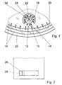
- Fig. 1 is a section of a kettle with a tubular heater 20 from below shown without cover.
- the tubular heater 20 is on a heat diffuser plate 16 attached from aluminum, which in turn attached to a container bottom 22 made of stainless steel is.
- a temperature sensor is on the heat diffuser plate 16 with a rivet pin 30 10 attached, which is formed by a bimetallic element.
- the temperature sensor 10 is at a distance from the tubular heater 20 in one area arranged, in which experience shows a permanent lime layer on the Deposits water-facing side of the container bottom 22.
- a limited cross-sectional area 12 a defined heat flow 14 passed.
- the area is largely thermally decoupled except in the direction of the water, so that the supplied Heat flow 14 can be removed almost exclusively to the water, namely the area via a crescent-shaped recess 18 in the heat diffuser plate 16 in the direction thermally decoupled from the tubular heater 20.
- the bottom of the container 22 has a much lower thermal conductivity than the heat diffuser plate 16, so that a heat flow from the area of the temperature sensor 10 over the tank bottom 22 is negligible.
- the temperature sensor 10 simultaneously represents a device via which signals are output can be, namely by a temperature-dependent deformation of the bimetal element. If there is no or little lime layer in the area of the temperature sensor 10 thermal equilibrium at a relatively low temperature. The bimetal element remains in its position. Will heat dissipation from the area of the temperature sensor 10 hindered by a layer of lime, the temperature takes in this area too. A temperature-related increase in limescale can be caused by the temperature sensor 10 can be recorded exactly.
- a maximum permissible lime layer is exceeded and thus a certain predetermined one Temperature value, is not closer to part 24 of the bimetal element shown contact is interrupted and the tubular heater 20 is switched off.
- a shutdown signal specifically at a temperature value, between a maximum possible boiling point of water of 100 ° C and a response temperature of approx. 135 ° C of a conventional dry running sensor is the maximum but also equal to the response temperature of a conventional dry running sensor can be.
- an optical display element 26 is actuated or in via the bimetal element a viewing window 28 moved. Is this the case after switching off the kettle? Bimetal element back, the display element 26 remains in its position in which it was shifted by the bimetal element.
- the display element 26 can of a user can be recognized when descaling is due. Furthermore, the reason recognized for a lime-related shutdown of the tubular heater 20 on the display element 26 become.
- the display element 26 can be manually operated by the user be returned to its original position. By resetting the display element 26 is the contact interrupted by the bimetallic element to the tubular heater 20 restored.
- the temperature sensor 10 additionally serves as a dry running sensor, i.e. becomes the kettle operated without water, the specified temperature value is exceeded and the tubular heater 20 is switched off.
- a mechanical preload of the bimetal element can be installed in the kettle via an adjusting screw, not shown, and thus the temperature sensor 10 can be calibrated exactly.
- the temperature sensor 10 can be different Containers used and it can always switch off heating elements at one largely the same lime layer can be achieved.
Landscapes
- Engineering & Computer Science (AREA)
- Food Science & Technology (AREA)
- Cookers (AREA)
Abstract
Description
Claims (20)
- Behälter zur Erwärmung von Wasser mit wenigstens einem Temperatursensor (10) und mit einer Vorrichtung, die zumindest ein Signal ausgibt, sobald die erfaßte Temperatur einen vorgegebenen Temperaturwert überschreitet, dadurch gekennzeichnet, daß mit dem Temperatursensor (10) eine sich durch eine Kalkschicht einstellende Temperaturerhöhung erfaßbar ist und der vorgegebene Temperaturwert durch eine maximal zulässige Kalkschicht bestimmt ist.
- Behälter nach Anspruch 1, dadurch gekennzeichnet, daß der Temperatursensor (10) in einem Bereich angeordnet ist, in den über eine begrenzte Querschnittsfläche (12) ein Wärmestrom (14) geleitet und der bis auf in Richtung des Wassers weitgehend thermisch entkoppelt ist, so daß der zugeführte Wärmestrom (14) nahezu ausschließlich an das Wasser abführbar ist.
- Behälter nach Anspruch 2, dadurch gekennzeichnet, daß der Temperatursensor (10) mit einer Wärmediffusorplatte (16) zumindest thermisch verbunden ist und der Bereich des Temperatursensors (10) über eine Aussparung (18) in der Wärmediffusorplatte (16) entkoppelt ist.
- Behälter nach Anspruch 2, dadurch gekennzeichnet, daß ein Dickschichtheizelement integriert und der Bereich des Temperatursensors durch wenigstens einen vergrößerten Leiterzugabstand thermisch entkoppelt ist.
- Behälter nach einem der vorhergehenden Ansprüche, dadurch gekennzeichnet, daß die Vorrichtung zumindest ein integriertes Heizelement (20) bei Überschreiten des vorgegebenen Temperaturwerts abschaltet.
- Behälter nach einem der vorhergehenden Ansprüche, dadurch gekennzeichnet, daß die Vorrichtung ein auf eine Verkalkung hinweisendes optisches und/oder akustisches Signal ausgibt.
- Behälter nach einem der vorhergehenden Ansprüche, dadurch gekennzeichnet, daß der Temperatursensor (10) einstückig mit einem Trockenlaufsensor ausgeführt ist.
- Behälter nach einem der vorhergehenden Ansprüche, dadurch gekennzeichnet, daß der Temperatursensor (10) im montierten Zustand einstellbar ist.
- Behälter nach einem der vorhergehenden Ansprüche, dadurch gekennzeichnet, daß der Temperatursensor (10) zumindest ein Bimetallelement aufweist.
- Behälter nach einem der vorhergehenden Ansprüche, dadurch gekennzeichnet, daß die Vorrichtung eine stetige Anzeige der Dicke der Kalkschicht beinhaltet.
- Behälter nach einem der vorhergehenden Ansprüche, dadurch gekennzeichnet, daß der Temperatursensor (10) ein temperaturabhängiger Widerstand ist.
- Behälter nach einem der Ansprüche 1 bis 10, dadurch gekennzeichnet, daß der Temperatursensor (10) unmittelbar als Anzeigeelement wirkt.
- Behälter nach einem der Ansprüche 1 bis 10, dadurch gekennzeichnet, daß der Temperatursensor (10) unmittelbar als Schalter wirkt.
- Behälter nach einem der vorhergehenden Ansprüche, dadurch gekennzeichnet, daß der Temperatursensor (10) ein Steuersignal erzeugt, das über eine Kopplung ein Anzeigeelement steuert.
- Behälter nach einem der Ansprüche 1 bis 12 und 14, dadurch gekennzeichnet, daß der Temperatursensor (10) ein Steuersignal erzeugt, das über eine Kopplung einen Schalter steuert.
- Behälter nach Anspruch 9, dadurch gekennzeichnet, daß der Temperatursensor (10) ein Bimetallsensorelement ist, das mindestens einen Kontakt trägt, der mit mindestens einem zweiten Kontakt zusammenwirkt.
- Behälter nach Anspruch 16, dadurch gekennzeichnet, daß der zweite Kontakt auf einem Heizelement, insbesondere auf einem Dickschichtheizelement aufgebracht oder in dieses integriert ist.
- Behälter nach Anspruch 16, dadurch gekennzeichnet, daß der zweite Kontakt auf einer Haltevorrichtung an einem Heizelement aufgebracht oder in diese integriert ist.
- Behälter nach Anspruch 16, dadurch gekennzeichnet, daß der zweite Kontakt an einer vorhandenen Steuereinrichtung angeordnet ist.
- Behälter nach einem der Ansprüche 1 bis 10, dadurch gekennzeichnet, daß der Temperatursensor (10) und/oder eine ihm zugeordnete Anzeigevorrichtung in eine Steuereinheit integriert ist, die Mittel zu einer elektrischen Verbindung, insbesondere eine elektrische Kupplung und/oder Mittel zur Steuerung einer Heizung, insbesondere ein Dampfstop oder Trockengehschutz enthalten.
Applications Claiming Priority (2)
| Application Number | Priority Date | Filing Date | Title |
|---|---|---|---|
| DE19960497 | 1999-12-15 | ||
| DE19960497A DE19960497A1 (de) | 1999-12-15 | 1999-12-15 | Behälter zur Erwärmung von Wasser |
Publications (2)
| Publication Number | Publication Date |
|---|---|
| EP1108385A1 true EP1108385A1 (de) | 2001-06-20 |
| EP1108385B1 EP1108385B1 (de) | 2005-02-16 |
Family
ID=7932763
Family Applications (1)
| Application Number | Title | Priority Date | Filing Date |
|---|---|---|---|
| EP00124546A Expired - Lifetime EP1108385B1 (de) | 1999-12-15 | 2000-11-09 | Behälter zur Erwärmung von Wasser |
Country Status (2)
| Country | Link |
|---|---|
| EP (1) | EP1108385B1 (de) |
| DE (2) | DE19960497A1 (de) |
Cited By (3)
| Publication number | Priority date | Publication date | Assignee | Title |
|---|---|---|---|---|
| WO2006038109A2 (en) | 2004-10-01 | 2006-04-13 | Merloni Termosanitari S.P.A. | Accumulator water heater, flange for accumulator water heater and control method for water heater scaling |
| WO2007017624A1 (en) * | 2005-08-11 | 2007-02-15 | Otter Controls Ltd | Scale detection on water heating elements |
| CN111928963A (zh) * | 2020-08-05 | 2020-11-13 | 合肥齐飞信息技术有限公司 | 一种热敏传感器 |
Families Citing this family (3)
| Publication number | Priority date | Publication date | Assignee | Title |
|---|---|---|---|---|
| DE10313501A1 (de) * | 2003-03-25 | 2004-10-14 | Dieter Wildfang Gmbh | Sanitäre Wasserauslaufeinheit, insbesondere Strahlregler oder Brause |
| DE102008008020B4 (de) * | 2008-02-07 | 2024-06-20 | Rational Ag | Verfahren zur Identifizierung von Fehler-Ereignissen in einem Gargerät mit zumindest einer Düse und Gargerät zur Durchführung eines solchen Verfahrens |
| DE102021215091A1 (de) | 2021-12-30 | 2023-07-06 | Robert Bosch Gesellschaft mit beschränkter Haftung | Vorrichtung zum Erhitzen von Wasser, Verfahren zum Identifizieren einer Verkalkung, Elektrogerät |
Citations (4)
| Publication number | Priority date | Publication date | Assignee | Title |
|---|---|---|---|---|
| GB1264464A (de) * | 1968-04-18 | 1972-02-23 | ||
| DE2638040A1 (de) * | 1976-08-24 | 1978-03-09 | Bosch Siemens Hausgeraete | Anzeigevorrichtung fuer den verkalkungsgrad von elektrischen hausgeraeten |
| FR2462893A1 (fr) * | 1979-08-09 | 1981-02-20 | Rowenta Werke Gmbh | Recipient de preparation de boissons chaudes avec indication d'entartrage |
| GB2292841A (en) * | 1994-08-26 | 1996-03-06 | Strix Ltd | Contact arrangement for a liquid heating vessel |
-
1999
- 1999-12-15 DE DE19960497A patent/DE19960497A1/de not_active Withdrawn
-
2000
- 2000-11-09 DE DE50009544T patent/DE50009544D1/de not_active Expired - Lifetime
- 2000-11-09 EP EP00124546A patent/EP1108385B1/de not_active Expired - Lifetime
Patent Citations (4)
| Publication number | Priority date | Publication date | Assignee | Title |
|---|---|---|---|---|
| GB1264464A (de) * | 1968-04-18 | 1972-02-23 | ||
| DE2638040A1 (de) * | 1976-08-24 | 1978-03-09 | Bosch Siemens Hausgeraete | Anzeigevorrichtung fuer den verkalkungsgrad von elektrischen hausgeraeten |
| FR2462893A1 (fr) * | 1979-08-09 | 1981-02-20 | Rowenta Werke Gmbh | Recipient de preparation de boissons chaudes avec indication d'entartrage |
| GB2292841A (en) * | 1994-08-26 | 1996-03-06 | Strix Ltd | Contact arrangement for a liquid heating vessel |
Cited By (6)
| Publication number | Priority date | Publication date | Assignee | Title |
|---|---|---|---|---|
| WO2006038109A2 (en) | 2004-10-01 | 2006-04-13 | Merloni Termosanitari S.P.A. | Accumulator water heater, flange for accumulator water heater and control method for water heater scaling |
| WO2006038109A3 (en) * | 2004-10-01 | 2006-07-13 | Merloni Termosanitari Spa | Accumulator water heater, flange for accumulator water heater and control method for water heater scaling |
| RU2419028C2 (ru) * | 2004-10-01 | 2011-05-20 | Аристон Термо С.П.А. | Накопительный водонагреватель, фланец накопительного водонагревателя и способ контроля образования накипи в водонагревателе |
| WO2007017624A1 (en) * | 2005-08-11 | 2007-02-15 | Otter Controls Ltd | Scale detection on water heating elements |
| CN111928963A (zh) * | 2020-08-05 | 2020-11-13 | 合肥齐飞信息技术有限公司 | 一种热敏传感器 |
| CN111928963B (zh) * | 2020-08-05 | 2022-01-07 | 江西浩风电器有限公司 | 一种热敏传感器 |
Also Published As
| Publication number | Publication date |
|---|---|
| DE50009544D1 (de) | 2005-03-24 |
| EP1108385B1 (de) | 2005-02-16 |
| DE19960497A1 (de) | 2001-06-21 |
Similar Documents
| Publication | Publication Date | Title |
|---|---|---|
| DE69112536T2 (de) | Temperaturfühler. | |
| EP1166698B1 (de) | Boiler und Dampfgargerät mit einem derartigen Boiler | |
| EP1152639B1 (de) | Elektrische Heizeinheit, insbesondere für flüssige Medien | |
| EP3775701B1 (de) | Haushalts-dampfbehandlungsgerät | |
| EP1108385B1 (de) | Behälter zur Erwärmung von Wasser | |
| EP1255420B1 (de) | Anzeigevorrichtung | |
| DE69328674T2 (de) | Verbesserte kontrolelemente für elektrische wasserheizkessel | |
| DE69737622T2 (de) | Temperaturregel- und Sicherheitsvorrichtung für eine glaskeramische Kochflache, angeordnet zum Vermeiden seiner Überhitzung | |
| DE3336758C2 (de) | Elektronisch betätigte Kondensat-Ablaßventilvorrichtung zum Ablassen von Kondensat aus einem Dampfsystem | |
| DE60131255T2 (de) | Temperatursensor | |
| WO2002031453A1 (de) | Kältegerät mit temperatursensor | |
| EP2775792B1 (de) | Kocheinrichtung | |
| DE102007012379A1 (de) | Kochfeldvorrichtung | |
| DE102006016956A1 (de) | Vorrichtung zum Bestimmen thermischer Größen in einem Gargerät | |
| DE102018104371A1 (de) | Dampfgenerator für ein Gargerät, Gargerät, Verfahren zum Bestimmen eines Füllzustandes eines Dampfgenerators sowie Verfahren zur Bestimmung der Verkalkung eines Heizregisters in einem Dampfgenerator | |
| DE102015205496A1 (de) | Erhitzen von Flüssigkeit in einem Haushaltsgerät | |
| DE102013102110A1 (de) | Kocheinrichtung | |
| DE102013102112A1 (de) | Kocheinrichtung | |
| DE10009515A1 (de) | Grillgerät mit zumindest einem elektrischen Heizelement | |
| DE3317100A1 (de) | Signaleinrichtung fuer kochplatten, insbesondere glaskeramik-kochplatten | |
| EP2775791B1 (de) | Kocheinrichtung | |
| DE2704146A1 (de) | Haushaltskaffeemaschine mit verkalkungsanzeige | |
| DE8914470U1 (de) | Steuereinrichtung für eine elektrische Heizeinheit | |
| DE102013102118A1 (de) | Kocheinrichtung und Verfahren zum Betreiben | |
| DE1060065B (de) | Elektrischer Fluessigkeitserhitzer mit Sicherheitsschalter |
Legal Events
| Date | Code | Title | Description |
|---|---|---|---|
| PUAI | Public reference made under article 153(3) epc to a published international application that has entered the european phase |
Free format text: ORIGINAL CODE: 0009012 |
|
| AK | Designated contracting states |
Kind code of ref document: A1 Designated state(s): DE FR GB |
|
| AX | Request for extension of the european patent |
Free format text: AL;LT;LV;MK;RO;SI |
|
| 17P | Request for examination filed |
Effective date: 20011220 |
|
| AKX | Designation fees paid |
Free format text: DE FR GB |
|
| 17Q | First examination report despatched |
Effective date: 20030715 |
|
| RAP1 | Party data changed (applicant data changed or rights of an application transferred) |
Owner name: BSH BOSCH UND SIEMENS HAUSGERAETE GMBH |
|
| GRAP | Despatch of communication of intention to grant a patent |
Free format text: ORIGINAL CODE: EPIDOSNIGR1 |
|
| GRAS | Grant fee paid |
Free format text: ORIGINAL CODE: EPIDOSNIGR3 |
|
| GRAA | (expected) grant |
Free format text: ORIGINAL CODE: 0009210 |
|
| AK | Designated contracting states |
Kind code of ref document: B1 Designated state(s): DE FR GB |
|
| REG | Reference to a national code |
Ref country code: GB Ref legal event code: FG4D Free format text: NOT ENGLISH |
|
| REF | Corresponds to: |
Ref document number: 50009544 Country of ref document: DE Date of ref document: 20050324 Kind code of ref document: P |
|
| GBT | Gb: translation of ep patent filed (gb section 77(6)(a)/1977) |
Effective date: 20050316 |
|
| ET | Fr: translation filed | ||
| PLBE | No opposition filed within time limit |
Free format text: ORIGINAL CODE: 0009261 |
|
| STAA | Information on the status of an ep patent application or granted ep patent |
Free format text: STATUS: NO OPPOSITION FILED WITHIN TIME LIMIT |
|
| 26N | No opposition filed |
Effective date: 20051117 |
|
| REG | Reference to a national code |
Ref country code: FR Ref legal event code: PLFP Year of fee payment: 16 |
|
| REG | Reference to a national code |
Ref country code: FR Ref legal event code: CD Owner name: BSH HAUSGERATE GMBH Effective date: 20151022 |
|
| REG | Reference to a national code |
Ref country code: FR Ref legal event code: PLFP Year of fee payment: 17 |
|
| PGFP | Annual fee paid to national office [announced via postgrant information from national office to epo] |
Ref country code: FR Payment date: 20161124 Year of fee payment: 17 Ref country code: DE Payment date: 20161130 Year of fee payment: 17 Ref country code: GB Payment date: 20161124 Year of fee payment: 17 |
|
| REG | Reference to a national code |
Ref country code: DE Ref legal event code: R119 Ref document number: 50009544 Country of ref document: DE |
|
| GBPC | Gb: european patent ceased through non-payment of renewal fee |
Effective date: 20171109 |
|
| REG | Reference to a national code |
Ref country code: FR Ref legal event code: ST Effective date: 20180731 |
|
| PG25 | Lapsed in a contracting state [announced via postgrant information from national office to epo] |
Ref country code: FR Free format text: LAPSE BECAUSE OF NON-PAYMENT OF DUE FEES Effective date: 20171130 Ref country code: DE Free format text: LAPSE BECAUSE OF NON-PAYMENT OF DUE FEES Effective date: 20180602 |
|
| PG25 | Lapsed in a contracting state [announced via postgrant information from national office to epo] |
Ref country code: GB Free format text: LAPSE BECAUSE OF NON-PAYMENT OF DUE FEES Effective date: 20171109 |