EP1107290A2 - Wafer scrubbing brush core - Google Patents
Wafer scrubbing brush core Download PDFInfo
- Publication number
- EP1107290A2 EP1107290A2 EP00310761A EP00310761A EP1107290A2 EP 1107290 A2 EP1107290 A2 EP 1107290A2 EP 00310761 A EP00310761 A EP 00310761A EP 00310761 A EP00310761 A EP 00310761A EP 1107290 A2 EP1107290 A2 EP 1107290A2
- Authority
- EP
- European Patent Office
- Prior art keywords
- holes
- core
- brush
- recited
- bore
- Prior art date
- Legal status (The legal status is an assumption and is not a legal conclusion. Google has not performed a legal analysis and makes no representation as to the accuracy of the status listed.)
- Withdrawn
Links
Images



Classifications
-
- H—ELECTRICITY
- H10—SEMICONDUCTOR DEVICES; ELECTRIC SOLID-STATE DEVICES NOT OTHERWISE PROVIDED FOR
- H10P—GENERIC PROCESSES OR APPARATUS FOR THE MANUFACTURE OR TREATMENT OF DEVICES COVERED BY CLASS H10
- H10P72/00—Handling or holding of wafers, substrates or devices during manufacture or treatment thereof
- H10P72/04—Apparatus for manufacture or treatment
- H10P72/0402—Apparatus for fluid treatment
- H10P72/0406—Apparatus for fluid treatment for cleaning followed by drying, rinsing, stripping, blasting or the like
- H10P72/0411—Apparatus for fluid treatment for cleaning followed by drying, rinsing, stripping, blasting or the like for wet cleaning or washing
- H10P72/0412—Apparatus for fluid treatment for cleaning followed by drying, rinsing, stripping, blasting or the like for wet cleaning or washing using mainly scrubbing means, e.g. brushes
-
- B—PERFORMING OPERATIONS; TRANSPORTING
- B08—CLEANING
- B08B—CLEANING IN GENERAL; PREVENTION OF FOULING IN GENERAL
- B08B1/00—Cleaning by methods involving the use of tools
- B08B1/30—Cleaning by methods involving the use of tools by movement of cleaning members over a surface
- B08B1/32—Cleaning by methods involving the use of tools by movement of cleaning members over a surface using rotary cleaning members
- B08B1/34—Cleaning by methods involving the use of tools by movement of cleaning members over a surface using rotary cleaning members rotating about an axis parallel to the surface
Definitions
- This invention relates generally to semiconductor wafer fabrication, and more particularly to semiconductor wafer scrubbing equipment.
- semiconductor devices are fabricated from semiconductor wafers, which are subjected to numerous processing operations. These operations include, for example, impurity implants, gate oxide generation, inter-metal oxide depositions, metallization depositions, photolithography pattering, etching operations, chemical mechanical polishing (CMP), etc. Although these processes are performed in ultra clean environments, the very nature of many of the process operations is to blame for the generation of surface particles and residues. For instance, when CMP operations are performed, a film of particles and/or metal contaminants are commonly left behind.
- wafer cleaning operations have become a standard procedural requirement after certain process steps. Although cleaning operations are rather procedural, the equipment and chemicals implemented to perform the actual cleaning are highly specialized. This specialization is important because each wafer, being at different stages of fabrication, represents a significant investment in terms of raw materials, equipment fabrication time, and associated research and development.
- the cleaning systems typically include one or more brush boxes in which wafers are scrubbed. Each brush box includes a pair of brushes, such that each brush scrubs a respective side of a wafer.
- TTB fluid delivery is accomplished by implementing brush cores that have a plurality of holes that allow fluids being fed into the brush core at a particular pressure to be released into an outer brush surface.
- the outer brush surface is made out of a very porous and soft material so that direct contact with the delicate surface of a wafer does not cause scratches or other damage.
- the outer brush surface is a made out of polyvinyl alcohol (PVA) foam.
- PVA polyvinyl alcohol
- any uneven application will have a severe impact on the wafer being processed. For instance, if more HF is applied to one part of the wafer and less is applied to another part of the wafer, the surface of the processed wafer may exhibit performance impacting etch variations due to experienced chemical concentration variations.
- engineered chemicals such as hydrofluoric acid (HF) containing etch chemicals
- Figure 1A provides a simplified diagram 10 of a prior art brush core 12 having a plurality of holes 12a.
- the brush core 12 has a center bore 12b which is configured to receive fluids from a fluid input 16 at one end of the brush core 12.
- the brush core 12 is shown having a brush 14 mounted thereon to illustrate that fluid that enters the bore 12b exits the holes 12a soaks the brush 14 that is designed to contact a wafer.
- This simplistic diagram also illustrates fluid flow lines 18a and 18b, in which fluid lines 18a illustrate that more fluid tends to flow out of holes 12a near the fluid input than at the opposite end. It is believed that this occurs because chemicals are either not applied to the brush core 12 at a sufficient pressure or the holes 12 are too large and/or are improperly arranged and thus allow gravity to pull more fluid out of the brush core 12 near the fluid input 16 than at the opposite end.
- Some of these prior art brush cores 12 have a center bore 12b that is about 0.36 inch in diameter or larger and holes 12a that are about 0.13 inch in diameter or larger. To compensate for the larger size of these dimensions and to attempt to prevent the uneven delivery of fluids, cleaning systems need to deliver fluids to the brush cores 12 at higher pressures. These higher pressures range between 30 to 35 PSI or higher. However, the application of higher pressures require the cleaning system to have access to facilities and associated equipment that can deliver the desired controlled pressures at all times. However, cleaning systems are installed in clean rooms around the world having different facilities which may or may not be able to deliver the recommended pressures. Additionally, the holes 12a of most prior art brush cores 12 are arranged such that one hole 12a' is directly opposite of another hole 12a'. This arrangement is also believed to contribute to the higher outflow of fluids near the fluid input 16 than at the opposite end.
- the present invention fills these needs by providing a brush core for use in scrubbing substrates.
- the substrate can be any substrate that may need to undergo a scrubbing operation to complete a cleaning operation, etching operation, or other preparation.
- the substrate can be a semiconductor wafer, a disk, or any other type of work piece that will benefit from a brush core that can deliver uniform controlled amounts of fluid through the brush along an entire length of the brush core.
- the present invention can be implemented in numerous ways, including as a process, an apparatus, a system, a device, or a method. Several inventive embodiments of the present invention are described below.
- a brush core for use in substrate scrubbing is disclosed.
- the brush core is defined by a tubular core extending between a first end and a second end.
- a bore is defined through a middle of the tubular core.
- a first and second plurality of holes are provided. Each hole of the first and second plurality of holes is defined through the tubular core to define a path to the bore.
- the first plurality of holes is defined along a first line that extends between the first end and the second end and the second plurality of holes is defined along a second line that extends between the first end and the second end.
- the first line and the second line are repeated around the tubular core and the first line and the second line alternate around the tubular core, and the holes of the first plurality of holes are offset relative to the holes of the second plurality of holes.
- a brush core is disclosed.
- the brush core is defined by a tubular core having a length that extends between a first end and a second end.
- the first end has an opening into a bore that is defined through a middle of the tubular core and extends along an inner length of the tubular core.
- a first plurality of holes are oriented along a plurality of first lines that extend in the direction of the length of the tubular core, and each of the first plurality of holes define paths to the bore of the tubular core.
- a second plurality of holes are oriented along a plurality of second lines that extend in the direction of the length of the tubular core, and each of the second plurality of holes define paths to the core of the tubular core.
- the plurality of first lines and the plurality of second lines alternate and the holes of the first and second plurality of holes are equally spaced apart.
- the holes of the second plurality of holes are offset relative to the holes of the first plurality of holes.
- a method of making a brush core includes providing a tubular core having a length that is configured to extend over a substrate.
- a bore is defined through a center of the tubular core.
- a first plurality of holes oriented along a plurality of first lines that extend in the direction of the length of the tubular core is defined. Each of the first plurality of holes is configured to establish paths to the bore of the tubular core.
- a second plurality of holes oriented along a plurality of second lines that extend in the direction of the length of the tubular core is defined. Each of the second plurality of holes is configured to establish paths to the core of the tubular core.
- the defined first plurality of holes are configured to be offset from the defined second plurality of holes.
- the embodiments of the present invention provide brush cores for delivering a uniform fluid distribution throughout the core.
- the uniform fluid distribution is achieved by designing specially placed and sized holes into the brush core.
- the holes define paths to a specially designed center bore, which is configured and sized to quickly pressurize the bore such that the delivered fluid exits the plurality of holes at about the same rate. Achieving this substantial even outflow of fluid from the core along the entire length of the brush core ensures that the outer brush receives equal amounts of fluids during an application process.
- even outflow of fluids is especially important when the fluids are engineered chemicals, such as etchants, that are designed to remove certain material particles, films, or layers.
- Figure 1A provides a simplified diagram of a prior art brush core having a plurality of holes.
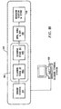
- Figure 1B shows a wafer cleaning station of the present invention that may be controlled in an automated way by a cleaning control station.
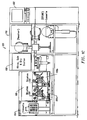
- FIG. 1C shows a more detailed schematic of an exemplary wafer cleaning station, in accordance with one embodiment of the present invention.
- Figure 2A illustrates a simplified three-dimensional diagram of a pair of brushes scrubbing a top surface and a bottom surface of a wafer, in accordance with one embodiment of the present invention.
- Figures 2B and 2C illustrate cross-sectional views of two different orientations for scrubbing a wafer, in accordance with one embodiment of the present invention.
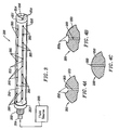
- Figure 3 illustrates a three-dimensional view of a brush core, in accordance with one embodiment of the present invention.
- Figures 4A through 4C illustrate alternative channel geometries for a tubular core, in accordance with one embodiment of the present invention.
- Figure 5A shows a cross-sectional view of the brush core, in accordance with one embodiment of the present invention.
- Figures 5B and 5C illustrate cross-sectional views A-A and B-B along a brush core, in accordance with one embodiment of the present invention.
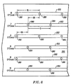
- Figure 6 illustrates a simplified diagram of a plurality of channels having a plurality of holes, in accordance with one embodiment of the present invention.
- the substrate can be any substrate that may need to undergo a scrubbing operation to complete a cleaning operation, etching operation, or other preparation. It will be obvious, however, to one skilled in the art, that the present invention may be practiced without some or all of these specific details. In other instances, well known process operations have not been described in detail in order not to unnecessarily obscure the present invention.
- FIG. 1B shows a wafer cleaning station 100 of the present invention that may be controlled in an automated way by a cleaning control station 102.
- the wafer cleaning station 100 includes a sender station 104, a cleaning stage 106, a spin-rinse and dry (SRD) station 108, and a receiver station 110.
- semiconductor wafers are initially placed into the sender station 104.
- the sender station 104 then delivers a wafer (one-at-a-time) to the cleaning stage 106.
- the cleaning stage 106 is divided into a first cleaning stage 106a and a second cleaning stage 106b, although having just one cleaning stage 106 will also work.
- the wafer is passed through an exit spray in order to remove the cleaning fluids and any contaminants.
- the SRD station 108 dries the wafer and then it is delivered to the receiver station 110 for temporary storage.
- FIG. 1C shows a more detailed schematic of an exemplary wafer cleaning station 100.
- Both the sender station 104 and the receiving station 110 are preferably adapted to receive a cassette containing a number of wafers.
- the first and second cleaning stages 106a and 106b preferably include a set of PVA brushes 120 that are very soft and porous. As will be described below, the brushes 120 are mounted on brush cores 200 of the present invention. As is well known, the brushes 120 are capable of scrubbing the wafer clean without damaging the delicate surface.
- Figure 2A illustrates a simplified three-dimensional diagram of a pair of brushes 120a and 120b for scrubbing a top surface and a bottom surface, respectively, of a wafer 130.
- the wafer 130 is caused to rotate in a particular direction while the brushes 120 rotate around an axis of rotation while the surface of the brushes 120 are in contact with the surfaces of the wafer 130.
- the brushes 120a and 120b are mounted on brush cores 200a and 200b.
- the brush cores 200 are configured to have at one end, a fluid inlet 201 which connects to tubing 202.
- the tubing 202 will thus supply the desired fluids to a bore 270 within the brush core 200.
- the brush core 200 as will be described in greater detail below, will have a plurality of holes 260 that will allow the fluids provided into the bore 270 to uniformly exit the brush core 200 (i.e., therefore evenly supplying the desired fluid to the brushes 120).
- Figures 2B and 2C illustrate cross-sectional views of two different orientations for scrubbing a wafer 130, in accordance with one embodiment of the present invention.
- the wafer is held horizontally while a top brush 120a scrubs the top surface of the wafer 130, and a bottom brush 120b scrubs the bottom surface of the wafer 130.
- the wafer 130 is configured to rotate (using rollers not shown) at the same time that the brushes 120 rotate to ensure that the entire surface area of the wafer is properly scrubbed to remove contaminants or etch the surface to a desired degree.
- Figure 2B illustrates a horizontal wafer scrubber 100b.
- Figure 2C illustrates a vertical wafer scrubber 100c in which the wafer 130 is scrubbed while in a vertical position.
- the wafer 130 sits on a pair of rollers of the scrubber 100c.
- the brushes 120 are configured to rotate in a desired direction such that both sides of the wafer 130 are evenly scrubbed, using an equal and opposite pressure on each side of the wafer 130.
- FIG. 3 illustrates a three-dimensional view of a brush core 200, in accordance with one embodiment of the present invention.
- the brush core 200 is defined by a tubular core 250 that extends between a first end 253 and a second end 251.
- the tubular core is configured to include, in one embodiment, a plurality of channels 252 which are recessed into the surface of the tubular core 250.
- a fluid source 263 supplies fluid by way of tubing (not shown) into the bore 270 of the tubular core 250 such that the fluid is evenly distributed to each of the plurality of holes 260.
- the plurality of holes 260 of one channel 252 are arranged in an offset configuration relative to holes defined in an adjacent respective channel 252.
- one channel may include a first plurality of holes 260 aligned along a first line across the length of the tubular core 250, and the next channel that is adjacent to the first channel will have its plurality of holes 260 defined along a second line across the length of the tubular core 250.
- the holes 260 defined in the adjacent channel 252 will be offset relative to the holes of its respective adjacent channel 252.
- the holes 260 will be evenly spaced apart and defined along the channel 252 that traverses the length of the tubular core 250.
- the holes 260 of the adjacent channel are shifted by an amount that is equal to about half of the separation distance between the holes of the first channel.
- the offset can be any amount so long as some offset is provided. In this manner, any fluid provided by the fluid source 263 into the bore that is defined through the tubular core 250 will evenly distribute into the bore and emanate out from all of the plurality of holes defined through the tubular core 250.
- the first end 253 of the brush core 200 includes a threaded insert 262 and an extension 264.
- This threaded insert 262 and extension 264 are configured to provide a way to connect up to an appropriate fluid line which will deliver fluids (e.g ., chemicals, DI water, or mixtures of fluids) to the bore 270 of the tubular core 250.
- the second end 251 of the brush core 200 includes a connection hole 256 for holding the second end of the brush core 200 in place when it is installed into a suitable brush box mechanism. Also shown are a plurality of locking pin holes 254 for engaging the tubular core 250 and enabling the application of a torque rotation to the brush core when the brush box requires the brush core to rotate about a defined axis.
- Figures 4A through 4C illustrate alternative channel geometries for the tubular core 250, in accordance with one embodiment of the present invention.
- a radial channel 252 can be defined into the tubular core 250 so that when the brush 120 is mounted on the brush core 200, any fluid provided through the plurality of holes 260 can be distributed along the channel and the length of the tubular core 250.
- Figure 4B illustrates an alternative embodiment of the channel 252a in which a slotted channel is provided to achieve the distribution of the fluids along the length of the tubular core 250.
- Figure 5A shows a cross-sectional view of the brush core 200, in accordance with one embodiment of the present invention.
- the brush core 200 will include a bore 270 which is defined along an inner length of the tubular core 250.
- the plurality of holes 260 illustrated along the top of the cross section are shown to be offset relative to the plurality of holes 260 defined along the bottom of the cross-sectional view. This offset design is configured to allow the even distribution of a fluid flow through the entire length of the bore 270, and thus allow an equal outflow of the fluid flow through each of the plurality of holes 260.
- the present design is configured to allow a fluid flow having a reduced pressure to rapidly fill the bore 270 and reach equilibrium such that an equal flow of fluid will emanate from the plurality of holes 260 around the entire brush core 200.
- holes such as 260a defined near the first end 253 of the brush core 200 will exhibit about the same outflow of fluids as holes such as 260b defined at the second end 251 of the brush core 200.
- Figures 5B and 5C illustrate cross-sectional views A-A and B-B along the brush core 200, in accordance with one embodiment of the present invention.
- Figure 5B illustrates the cross-sectional view of cross section A-A, and shows how the holes 260 are arranged around the tubular core 250.
- holes are defined around the tubular core 250 at 12 o'clock, 2 o'clock, 4 o'clock, 6 o'clock, 8 o'clock, and 10 o'clock.
- cross section A-A only holes 260 at 12 o'clock, 4 o'clock, and 8 o'clock, are exposed to the fluid flow that travels down the bore 270.
- the bore 270 will have a diameter ranging between about 0.060 inch and about 0.35 inch, and more preferably, between about 0.125 inch and about 0.30 inch, and most preferably at about 0.25 inch. It should be noted that the diameter of the bore 270 is substantially smaller than that typically used or suggested for brush cores of the prior art. By reducing the diameter of the bore 270 to such a reduced diameter, it has been tested that the fluid flow that enters the bore 270 will rapidly fill the volume of the bore 270 within the brush core 250.
- each of the plurality of holes 260 should have a diameter ranging between about 0.005 inch and about 0.092 inch, and most preferably, about 0.050 inch. It should be noted that the diameter of each of the plurality of holes 260 is also substantially reduced, which is configured in conjunction with the reduced bore 270 diameter to distribute any fluid flow delivered to the brush core 200 in a more even and distributed manner throughout the entire length of the brush core 200.
- the brush core 200 when the brush core 200 is designed for a 300 mm wafer scrubbing application, the brush core may have six channels 252 around the tubular core 250. Of course, more or less channels may be used ( e.g ., ranging between 2 and 12 channels).
- the total length L A of the exemplary brush core 200 is about 14 inches, and the brush 120 will thus have a length L B of about 13 inches. In this embodiment, the length L C of the channel 252 will be about 11 inches.
- the length of the brush core 200 can vary and the number of holes within the channels 252 can also vary.
- Figure 6 illustrates a simplified diagram of a plurality of channels 252 having a plurality of holes 260, in accordance with one embodiment of the present invention.
- a channel will be provided at 12 o'clock, 2 o'clock, 4 holes 260 along the channels for 12 o'clock, 4 o'clock, and 8 o'clock begin at the same location of their respective channel 252.
- Each of the plurality of holes 260 are separated by a separation distance S. In one embodiment, the separation distance is about 1.26 inch.
- the separation distance S is selected such that an even spacing can be distributed along the distance of a selected channel. Thus, if the channel is longer or shorter, the separation S will be modified to meet the desired length of a given channel.
- the channel length is about 11 inches, and therefore the separation between each of the plurality of holes 260 is as described above about 1.26 inch.
- the holes in the adjacent channels 252 defined at 2 o'clock, 6 o'clock, and 10 o'clock, are offset relative to the holes of the first plurality of channels defined at 12 o'clock, 4 o'clock, and 8 o'clock.
- This offset is preferably about half the distance of the separation parameter S.
- the offset between the channel of 12 o'clock and 2 o'clock is defined by an offset separation (OS) of about 0.63 inch. It should be understood that these parameters are only exemplary in nature and may be modified so long as some offset orientation is maintained to ensure even distribution of a fluid that may be provided into the bore 270.
- the brush core of the present invention can be modified for use in scrubbing any number of substrate types, for example, semiconductor wafers, hard drive discs, flat panel displays, and the like. Additionally, the brush core can be modified for substrate scrubbing applications of any size, for example,100 mm wafers, 200 mm wafers, 300 mm wafers, larger wafers, small hard disks, etc. It should also be noted that any number of fluids can be delivered through the brush (TTB), for example, DI water, ammonia containing chemical mixtures, HF containing chemical mixtures, surfactant containing chemical mixtures, and many other variations.
- TTB brush
Landscapes
- Cleaning Or Drying Semiconductors (AREA)
- Brushes (AREA)
Abstract
Description
In contrast, Figure 2C illustrates a
Claims (23)
- A brush core for use in substrate scrubbing, comprising:a tubular core extending between a first end and a second end;a bore defined through a middle of the tubular core;a first plurality of holes, each hole of the first plurality of holes being defined through the tubular core to define a path to the bore, the first plurality of holes being defined along a first line that extends between the first end and the second end; anda second plurality of holes, each hole of the second plurality of holes being defined through the tubular core to define the path to the bore, the second plurality of holes being defined along a second line that extends between the first end and the second end;wherein the first line and the second line are repeated around the tubular core and the first line and the second line alternate around the tubular core, and wherein the holes of the first plurality of holes are offset relative to the holes of the second plurality of holes.
- A brush core for use in substrate scrubbing as recited in claim 1, wherein each of the first lines and the second lines are defined along channels that are defined into an outer surface of the tubular core.
- A brush core for use in substrate scrubbing as recited in claim 2, wherein a first hole of the first plurality of holes is defined at a start of the channel defined along the first line that extends between the first end and the second end, and a first hole of the second plurality of holes is defined at an offset from the start of the channel defined along the second line that extends between the first end and the second end.
- A brush core for use in substrate scrubbing as recited in claim 3, further comprising:
a brush being configured to fit over the brush core. - A brush core for use in substrate scrubbing as recited in claim 1, wherein each of the first and second plurality of holes has a diameter ranging between about 0.005 inch and about 0.092 inch.
- A brush core for use in substrate scrubbing as recited in claim 5, wherein the bore has a diameter ranging between about 0.060 inch and about 0.35 inch.
- A brush core for use in substrate scrubbing as recited in claim 1, wherein the brush core is configured for a substrate in the range of 100 mm to 300 mm.
- A brush core for use in substrate scrubbing as recited in claim 3, wherein the first hole of the first plurality of holes is offset from the first hole of the second plurality of holes by about 0.36 inch, and each hole of the first and second plurality of holes is separated by about 1.26 inch.
- A brush core for use in substrate scrubbing as recited in claim 2, wherein the first plurality of holes are defined along three channels and the second plurality of holes are defined along three channels.
- A brush core for use in substrate scrubbing as recited in claim 2, wherein the 2 to 12 channels are defined around the tubular core.
- A brush core for use in substrate scrubbing as recited in claim 1, wherein a pressure ranging between about 1 PSI and 35 PSI is applied to the bore in order to distribute a fluid out of the first and second plurality of holes that extend between the first end and the second end.
- A brush core, comprising:a tubular core having a length that extends between a first end and a second end, the first end having an opening into a bore that is defined through a middle of the tubular core and extends along an inner length of the tubular core;a first plurality of holes oriented along a plurality of first lines that extend in the direction of the length of the tubular core, each of the first plurality of holes defining paths to the bore of the tubular core; anda second plurality of holes oriented along a plurality of second lines that extend in the direction of the length of the tubular core, each of the second plurality of holes defining paths to the core of the tubular core;wherein the plurality of first lines and the plurality of second lines alternate, the holes of the first and second plurality of holes are equally spaced apart, and the holes of the second plurality of holes are offset relative to the holes of the first plurality of holes.
- A brush core as recited in claim 12, further comprising:
a plurality of channels defined along the first and second plurality of lines, the plurality of channels defining recesses for distributing a fluid emanating from the bore and exiting the first and second plurality of holes. - A brush core as recited in claim 12, wherein each of the first and second plurality of holes has a diameter ranging between about 0.005 inch and about 0.092 inch.
- A brush core for using in substrate scrubbing as recited in claim 12, wherein the bore has a diameter ranging between about 0.060 inch and about 0.35 inch.
- A brush core for using in substrate scrubbing as recited in claim 12, wherein the brush core is configured for a substrate in the range of 100 mm to 300 mm.
- A brush core for using in substrate scrubbing as recited in claim 3, wherein a spacing that defines the equally spaced apart orientation of the first and second plurality of holes is about 1.26 inch for a 300 mm brush core, and the offset is about 0.36 inch.
- A method of making a brush core, comprising:providing a tubular core having a length that is configured to extend over a substrate;defining a bore through a center of the tubular core;defining a first plurality of holes oriented along a plurality of first lines that extend in the direction of the length of the tubular core, each of the first plurality of holes establishing paths to the bore of the tubular core; anddefining a second plurality of holes oriented along a plurality of second lines that extend in the direction of the length of the tubular core, each of the second plurality of holes establishing paths to the core of the tubular core;wherein the defined first plurality of holes are offset from the defined second plurality of holes.
- A method of making a brush core as recited in claim 18, further comprising:
forming a plurality of channels along the first and second plurality of lines, the plurality of channels defining recesses for distributing a fluid that is configured to emanate from the bore and exit the first and second plurality of holes. - A method of making a brush core as recited in claim 18, wherein each of the first and second plurality of holes has a diameter ranging between about 0.005 inch and about 0.092 inch.
- A method of making a brush core as recited in claim 20, wherein the bore has a diameter ranging between about 0.060 inch and about 0.35 inch.
- A method of making a brush core as recited in claim 21, further comprising:
delivering a fluid flow into the bore that is defined through the center of the tubular core, the delivered fluid flow having a pressure ranging between about 1 PSI and 15 PSI. - A method of making a brush core as recited in claim 22, wherein the fluid flow pressure is about 10 PSI.
Applications Claiming Priority (2)
| Application Number | Priority Date | Filing Date | Title |
|---|---|---|---|
| US454698 | 1999-12-03 | ||
| US09/454,698 US6240588B1 (en) | 1999-12-03 | 1999-12-03 | Wafer scrubbing brush core |
Publications (2)
| Publication Number | Publication Date |
|---|---|
| EP1107290A2 true EP1107290A2 (en) | 2001-06-13 |
| EP1107290A3 EP1107290A3 (en) | 2003-04-02 |
Family
ID=23805701
Family Applications (1)
| Application Number | Title | Priority Date | Filing Date |
|---|---|---|---|
| EP00310761A Withdrawn EP1107290A3 (en) | 1999-12-03 | 2000-12-04 | Wafer scrubbing brush core |
Country Status (4)
| Country | Link |
|---|---|
| US (2) | US6240588B1 (en) |
| EP (1) | EP1107290A3 (en) |
| JP (1) | JP3628959B2 (en) |
| TW (1) | TW476099B (en) |
Cited By (3)
| Publication number | Priority date | Publication date | Assignee | Title |
|---|---|---|---|---|
| WO2012170767A1 (en) * | 2011-06-08 | 2012-12-13 | Illinois Tool Works Inc. | Brush mandrel for pva sponge brush |
| USD727579S1 (en) | 2011-06-08 | 2015-04-21 | Illinois Tool Works Inc. | Brush core for a sponge brush |
| CN112605032A (en) * | 2020-12-03 | 2021-04-06 | 国网江苏省电力有限公司 | Energy big data service management platform |
Families Citing this family (38)
| Publication number | Priority date | Publication date | Assignee | Title |
|---|---|---|---|---|
| US6240588B1 (en) * | 1999-12-03 | 2001-06-05 | Lam Research Corporation | Wafer scrubbing brush core |
| US7955693B2 (en) * | 2001-04-20 | 2011-06-07 | Tolland Development Company, Llc | Foam composition roller brush with embedded mandrel |
| US20040049870A1 (en) * | 2002-06-21 | 2004-03-18 | Applied Materials, Inc. | Substrate scrubbing apparatus having stationary brush member in contact with edge bevel of rotating substrate |
| US20040040576A1 (en) * | 2002-08-29 | 2004-03-04 | Yuxia Sun | Wafer cleaning brush |
| US20050011535A1 (en) * | 2003-07-18 | 2005-01-20 | Randy Skocypec | Cleaning semiconductor wafers |
| WO2005016599A1 (en) | 2003-08-08 | 2005-02-24 | Mykrolys Corporation | Methods and materials for making a monolithic porous pad cast onto a rotatable base |
| WO2005065849A1 (en) * | 2003-12-26 | 2005-07-21 | Aion Co., Ltd. | Core for washing sponge roller |
| WO2005072560A2 (en) * | 2004-01-29 | 2005-08-11 | Applied Materials, Inc. | Methods and apparatus for installing a scrubber brush on a mandrel |
| ATE497255T1 (en) * | 2005-04-20 | 2011-02-15 | Freescale Semiconductor Inc | DEVICE FOR CLEANING CIRCUIT SUBSTRATES |
| WO2007067348A2 (en) * | 2005-12-06 | 2007-06-14 | Entegris, Inc. | A molded rotatable base for a porous pad |
| US7735177B1 (en) * | 2006-02-10 | 2010-06-15 | Lam Research Corporation | Brush core assembly |
| JP2009529241A (en) | 2006-03-07 | 2009-08-13 | アプライド マテリアルズ インコーポレイテッド | Scrubber brush with sleeve and brush mandrel for use with a scrubber brush |
| KR100833036B1 (en) * | 2006-07-25 | 2008-05-27 | 아이온 가부시키가이샤 | Core for Sponge Roller for Cleaning |
| WO2009147747A1 (en) * | 2008-06-06 | 2009-12-10 | アイオン株式会社 | Central core for cleaning sponge roller |
| EP2177128A1 (en) * | 2008-10-16 | 2010-04-21 | Koninklijke Philips Electronics N.V. | Fluid distributing brush assembly and method for operating the same |
| US20110182653A1 (en) * | 2010-01-26 | 2011-07-28 | Miller Kenneth C | Variable Pressure Brush/Pad |
| US8551253B2 (en) * | 2010-06-29 | 2013-10-08 | WD Media, LLC | Post polish disk cleaning process |
| USD682497S1 (en) | 2010-12-21 | 2013-05-14 | Entegris, Inc. | Substrate cleaning brush |
| USD707408S1 (en) * | 2011-04-20 | 2014-06-17 | Ebara Corporation | Roller for semiconductor wafer cleaning |
| TWD148170S (en) * | 2011-06-09 | 2012-07-11 | 荏原製作所股份有限公司 | Roller for substrate cleaning |
| US9202723B2 (en) | 2011-11-29 | 2015-12-01 | Illinois Tool Works, Inc. | Brush with cantilevered nodules |
| US8778087B2 (en) | 2012-04-03 | 2014-07-15 | Illinois Tool Works Inc. | Conical sponge brush for cleaning semiconductor wafers |
| USD735427S1 (en) * | 2013-02-01 | 2015-07-28 | Ebara Corporation | Roller shaft for substrate cleaning |
| USD728177S1 (en) * | 2013-02-01 | 2015-04-28 | Ebara Corporation | Roller shaft for substrate cleaning |
| USD735430S1 (en) * | 2013-09-24 | 2015-07-28 | Ebara Corporation | Roller shaft for substrate cleaning |
| TWD170203S (en) * | 2013-09-24 | 2015-09-01 | 荏原製作所股份有限公司 | Roller shaft for semiconductor cleaning |
| USD735429S1 (en) * | 2013-09-24 | 2015-07-28 | Ebara Corporation | Roller shaft for substrate cleaning |
| US10504753B2 (en) | 2013-12-13 | 2019-12-10 | Taiwan Semiconductor Manufacturing Co., Ltd. | Brush cleaning apparatus, chemical-mechanical polishing (CMP) system and wafer processing method |
| CN104043604A (en) * | 2014-06-26 | 2014-09-17 | 深圳市华星光电技术有限公司 | Cleaning brush structure |
| US9610615B2 (en) * | 2015-03-31 | 2017-04-04 | Taiwan Semiconductor Manufacturing Co., Ltd | Method and system for cleansing wafer in CMP process of semiconductor manufacturing fabrication |
| USD800401S1 (en) * | 2015-09-24 | 2017-10-17 | Ebara Corporation | Roller for substrate cleaning |
| JP1556809S (en) * | 2015-09-24 | 2016-08-22 | ||
| CN109037116B (en) * | 2018-08-31 | 2021-05-28 | 上海华力微电子有限公司 | Wafer cleaning device |
| TWI695741B (en) * | 2019-10-01 | 2020-06-11 | 力晶積成電子製造股份有限公司 | Post polishing cleaning apparatus |
| US11825933B2 (en) | 2020-01-08 | 2023-11-28 | Sharkninja Operating Llc | Liquid-permeable brush roll for use with cleaners including robotic cleaners |
| JP7478625B2 (en) * | 2020-08-25 | 2024-05-07 | 株式会社荏原製作所 | SUBSTRATE CLEANING APPARATUS, SUBSTRATE PROCESSING APPARATUS, SUBSTRATE C |
| WO2022115671A1 (en) * | 2020-11-30 | 2022-06-02 | Araca, Inc. | Brush for cleaning a substrate |
| JP7714819B2 (en) * | 2022-05-31 | 2025-07-29 | インテグリス・インコーポレーテッド | Cleaning brushes for semiconductor fabrication processes |
Family Cites Families (28)
| Publication number | Priority date | Publication date | Assignee | Title |
|---|---|---|---|---|
| DE448290C (en) | 1926-12-04 | 1927-08-15 | Demag Akt Ges | Device for brushing off rolling stock |
| DE674645C (en) | 1937-02-19 | 1939-04-19 | Bergedorfer Eisenwerk Akt Ges | Device for cleaning thin-walled objects, e.g. Insert plate for centrifugal drums |
| US2565743A (en) | 1946-03-05 | 1951-08-28 | Albert W Schaefer | Applicator for paints and the like |
| US2563048A (en) | 1946-05-17 | 1951-08-07 | Liebelt John Emanuel | Self-dispensing roller for applying paint |
| US2563049A (en) | 1947-09-05 | 1951-08-07 | John E Liebelt | Self-dispensing roller for applying paints |
| US2606334A (en) | 1949-02-21 | 1952-08-12 | James Warren Co | Roller paint applicator |
| FR1035235A (en) | 1951-04-09 | 1953-08-19 | Rodanet & Cie Ets | Improvements to paint rollers, automatic feed and hand |
| US2889696A (en) | 1954-05-24 | 1959-06-09 | Celanese Corp | Apparatus for treating yarn with a liquid |
| US3826581A (en) | 1972-08-10 | 1974-07-30 | B Henderson | Fountain liquid applicator |
| US4008503A (en) * | 1976-06-01 | 1977-02-22 | Tharp Marvin E | Rotary shower brush |
| JPS58182234A (en) | 1982-04-17 | 1983-10-25 | Dainippon Screen Mfg Co Ltd | Washing apparatus allowing use of plural kinds of brushes |
| US4461052A (en) | 1982-09-27 | 1984-07-24 | Mostul Thomas A | Scrubbing brush, rinse and sweeping equipment |
| JPS5986226A (en) * | 1982-11-08 | 1984-05-18 | Mitsubishi Electric Corp | Cleaning device for thin plate material |
| JPS59193029A (en) | 1983-04-15 | 1984-11-01 | Hitachi Ltd | Cleaning method and equipment |
| US4569695A (en) | 1983-04-21 | 1986-02-11 | Nec Corporation | Method of cleaning a photo-mask |
| JP2683940B2 (en) | 1989-08-09 | 1997-12-03 | 信越半導体 株式会社 | Automatic work cleaning device |
| DE9011982U1 (en) * | 1990-08-18 | 1990-12-13 | Schrandt, Wilhelm, 2914 Barßelermoor | Additional device for a drive device |
| US5345639A (en) | 1992-05-28 | 1994-09-13 | Tokyo Electron Limited | Device and method for scrubbing and cleaning substrate |
| US5639311A (en) | 1995-06-07 | 1997-06-17 | International Business Machines Corporation | Method of cleaning brushes used in post CMP semiconductor wafer cleaning operations |
| WO1997013590A1 (en) * | 1995-10-13 | 1997-04-17 | Ontrak Systems, Inc. | Method and apparatus for chemical delivery through the brush |
| US5713095A (en) * | 1996-05-30 | 1998-02-03 | Incredicoat, Inc. | Bifurcated paint roller and painting method |
| US5745945A (en) | 1996-06-28 | 1998-05-05 | International Business Machines Corporation | Brush conditioner for a semiconductor cleaning brush |
| US5875507A (en) | 1996-07-15 | 1999-03-02 | Oliver Design, Inc. | Wafer cleaning apparatus |
| US6070284A (en) * | 1998-02-04 | 2000-06-06 | Silikinetic Technology, Inc. | Wafer cleaning method and system |
| US6247197B1 (en) * | 1998-07-09 | 2001-06-19 | Lam Research Corporation | Brush interflow distributor |
| US6248009B1 (en) * | 1999-02-18 | 2001-06-19 | Ebara Corporation | Apparatus for cleaning substrate |
| US6240588B1 (en) * | 1999-12-03 | 2001-06-05 | Lam Research Corporation | Wafer scrubbing brush core |
| US6206599B1 (en) * | 2000-06-26 | 2001-03-27 | Franklyn Buchanan | Paint roller handle construction having a self contained paint supply |
-
1999
- 1999-12-03 US US09/454,698 patent/US6240588B1/en not_active Expired - Lifetime
-
2000
- 2000-12-01 TW TW089125667A patent/TW476099B/en not_active IP Right Cessation
- 2000-12-01 JP JP2000366826A patent/JP3628959B2/en not_active Expired - Fee Related
- 2000-12-04 EP EP00310761A patent/EP1107290A3/en not_active Withdrawn
-
2001
- 2001-05-22 US US09/863,781 patent/US6543084B2/en not_active Expired - Lifetime
Cited By (7)
| Publication number | Priority date | Publication date | Assignee | Title |
|---|---|---|---|---|
| WO2012170767A1 (en) * | 2011-06-08 | 2012-12-13 | Illinois Tool Works Inc. | Brush mandrel for pva sponge brush |
| CN103648666A (en) * | 2011-06-08 | 2014-03-19 | 伊利诺斯工具制品有限公司 | Brush mandrel for PVA sponge brush |
| US8898845B2 (en) | 2011-06-08 | 2014-12-02 | Llinois Tool Works, Inc. | Brush mandrel for PVA sponge brush |
| USD727579S1 (en) | 2011-06-08 | 2015-04-21 | Illinois Tool Works Inc. | Brush core for a sponge brush |
| CN103648666B (en) * | 2011-06-08 | 2015-09-23 | 伊利诺斯工具制品有限公司 | For the brush axle of polyvinylalcohol sponge brush |
| US9455163B2 (en) | 2011-06-08 | 2016-09-27 | Illinois Tool Works Inc. | Brush mandrel for PVA sponge brush |
| CN112605032A (en) * | 2020-12-03 | 2021-04-06 | 国网江苏省电力有限公司 | Energy big data service management platform |
Also Published As
| Publication number | Publication date |
|---|---|
| JP3628959B2 (en) | 2005-03-16 |
| US6240588B1 (en) | 2001-06-05 |
| US6543084B2 (en) | 2003-04-08 |
| TW476099B (en) | 2002-02-11 |
| JP2001237210A (en) | 2001-08-31 |
| US20010022008A1 (en) | 2001-09-20 |
| EP1107290A3 (en) | 2003-04-02 |
Similar Documents
| Publication | Publication Date | Title |
|---|---|---|
| US6240588B1 (en) | Wafer scrubbing brush core | |
| US5868863A (en) | Method and apparatus for cleaning of semiconductor substrates using hydrofluoric acid (HF) | |
| US8533895B2 (en) | Methods and materials for making a monolithic porous pad cast onto a rotatable base | |
| US5725414A (en) | Apparatus for cleaning the side-edge and top-edge of a semiconductor wafer | |
| US5723019A (en) | Drip chemical delivery method and apparatus | |
| US6616516B1 (en) | Method and apparatus for asymmetric processing of front side and back side of semiconductor substrates | |
| US6733596B1 (en) | Substrate cleaning brush preparation sequence, method, and system | |
| US6187684B1 (en) | Methods for cleaning substrate surfaces after etch operations | |
| US6550091B1 (en) | Double-sided wafer edge scrubbing apparatus and method for using the same | |
| US7879724B2 (en) | Method of manufacturing a semiconductor device and a semiconductor manufacturing equipment | |
| US20020094684A1 (en) | Foam cleaning process in semiconductor manufacturing | |
| US20040216841A1 (en) | Substrate processing apparatus | |
| US6093254A (en) | Method of HF-HF Cleaning | |
| US6557202B1 (en) | Wafer scrubbing brush core having an internal motor and method of making the same | |
| EP1459363B1 (en) | Method for post-etch and strip residue removal on coral films | |
| US6824622B2 (en) | Cleaner and method for removing fluid from an object | |
| US20030190810A1 (en) | Method of reducing particulate contamination during polishing of a wafer | |
| US20040000796A1 (en) | Wafer transfer apparatus and device and method for cleaning robot arm in wafer transfer apparatus | |
| KR20250065180A (en) | Brush aging pad, chemical mechanical polishing cleaning apparatus and method for aging brush |
Legal Events
| Date | Code | Title | Description |
|---|---|---|---|
| PUAI | Public reference made under article 153(3) epc to a published international application that has entered the european phase |
Free format text: ORIGINAL CODE: 0009012 |
|
| AK | Designated contracting states |
Kind code of ref document: A2 Designated state(s): AT BE CH CY DE DK ES FI FR GB GR IE IT LI LU MC NL PT SE TR |
|
| AX | Request for extension of the european patent |
Free format text: AL;LT;LV;MK;RO;SI |
|
| PUAL | Search report despatched |
Free format text: ORIGINAL CODE: 0009013 |
|
| AK | Designated contracting states |
Kind code of ref document: A3 Designated state(s): AT BE CH CY DE DK ES FI FR GB GR IE IT LI LU MC NL PT SE TR Designated state(s): AT BE CH CY DE DK ES FI FR GB GR IE IT LI LU MC NL PT SE TR |
|
| AX | Request for extension of the european patent |
Extension state: AL LT LV MK RO SI |
|
| RIC1 | Information provided on ipc code assigned before grant |
Ipc: 7B 08B 1/04 B Ipc: 7H 01L 21/00 A |
|
| 17P | Request for examination filed |
Effective date: 20030922 |
|
| AKX | Designation fees paid |
Designated state(s): AT BE CH CY DE DK ES FI FR GB GR IE IT LI LU MC NL PT SE TR |
|
| 17Q | First examination report despatched |
Effective date: 20071127 |
|
| STAA | Information on the status of an ep patent application or granted ep patent |
Free format text: STATUS: THE APPLICATION IS DEEMED TO BE WITHDRAWN |
|
| 18D | Application deemed to be withdrawn |
Effective date: 20110315 |