EP1107286A1 - Hochdruck-Quecksilberdampfentladungslampe - Google Patents
Hochdruck-Quecksilberdampfentladungslampe Download PDFInfo
- Publication number
- EP1107286A1 EP1107286A1 EP99124135A EP99124135A EP1107286A1 EP 1107286 A1 EP1107286 A1 EP 1107286A1 EP 99124135 A EP99124135 A EP 99124135A EP 99124135 A EP99124135 A EP 99124135A EP 1107286 A1 EP1107286 A1 EP 1107286A1
- Authority
- EP
- European Patent Office
- Prior art keywords
- sealing body
- end area
- discharge vessel
- high pressure
- mercury lamp
- Prior art date
- Legal status (The legal status is an assumption and is not a legal conclusion. Google has not performed a legal analysis and makes no representation as to the accuracy of the status listed.)
- Withdrawn
Links
Images


Classifications
-
- H—ELECTRICITY
- H01—ELECTRIC ELEMENTS
- H01J—ELECTRIC DISCHARGE TUBES OR DISCHARGE LAMPS
- H01J61/00—Gas-discharge or vapour-discharge lamps
- H01J61/02—Details
- H01J61/36—Seals between parts of vessels; Seals for leading-in conductors; Leading-in conductors
- H01J61/366—Seals for leading-in conductors
-
- H—ELECTRICITY
- H01—ELECTRIC ELEMENTS
- H01J—ELECTRIC DISCHARGE TUBES OR DISCHARGE LAMPS
- H01J61/00—Gas-discharge or vapour-discharge lamps
- H01J61/02—Details
- H01J61/36—Seals between parts of vessels; Seals for leading-in conductors; Leading-in conductors
- H01J61/361—Seals between parts of vessel
- H01J61/363—End-disc seals or plug seals
Definitions
- the invention relates to a high pressure mercury lamp.
- the invention relates especially to a super-high pressure mercury lamp in which a discharge vessel is filled with mercury in an amount greater than or equal to 0.16 mg/mm 3 , in which furthermore the mercury vapor pressure during operation is greater than or equal to a hundred and some dozen atm, and which is used as a backlight of a liquid crystal display device or the like.
- a metal halide lamp which is filled with mercury and a metal halide is used as the light source. Furthermore, smaller and smaller metal halide lamps, and more and more often point light sources have recently been produced, and lamps with extremely small distances between the electrodes have been used in practice.
- lamps with an extremely high mercury vapor pressure for example, with a vapor pressure greater than or equal to 200 bar (roughly 197 atm).
- the increased mercury vapor pressure suppresses broadening of the arc (the arc is contracted) and a considerable increase of the light intensity is desired; this is disclosed, for example, in Japanese patent disclosure document HEI 2-148561 (U.S. Patent No. 5,109,181) and in Japanese patent disclosure document HEI 6-52830 (U.S. Patent No. 5,497,049).
- Japanese patent disclosure document HEI 2-148561 discloses a high pressure mercury lamp in which a discharge vessel which has a pair of tungsten electrodes is filled with a rare gas, greater than or equal to 0.2 mg/mm 3 mercury and halogen in the range from 1 x 10 -6 to 1 x 10 -4 ⁇ mol/mm 3 , and which is operated with a wall load of greater than or equal to 1 W/mm 2 .
- the reason for the amount of mercury added being greater than or equal to 0.2 mg/mm 3 is to raise the mercury pressure, to multiply the continuous spectrum in the visible radiation range, especially in the red range, and to improve the color reproduction.
- the reason for the wall load of greater than or equal to 1 W/mm 2 is to increase the temperature in the coolest portion in order to increase the mercury pressure.
- Japanese patent disclosure document HEI 6-52830 discloses that, in addition to the above described amount of mercury, the value of the wall load, the amount of halogen, the shape of the discharge vessel, and the distance between the electrodes are fixed.
- this lamp is suited for a light source for a projector. Furthermore, it is described herein that the degree of maintenance of the screen illuminance is greater than when using a conventional lamp.
- a discharge vessel 61 has a hermetically sealed portion 62 formed on each of its two ends and in which a metal foil 63 made of molybdenum or the like is inserted.
- An electrode 64 is connected to the side of the respective metal foil 63 which points into the discharge vessel 61, while an outer lead 65 is connected to its side which points toward the exterior.
- Fig. 7 is a cross section taken along line 7-7 in Fig. 6. Between the metal foil 63 and the electrode 64, a gap S inevitably forms.
- a primary object of the present invention is to devise a super-high pressure mercury lamp with an internal pressure during operation of one hundred and some dozen atm, which has a new arrangement in which in the hermetically sealed portions neither damage the lamp nor shorten its operating service life.
- a side tube part is formed on each end of this discharge vessel which has a sealing body formed of a functional gradient material which is formed essentially of a dielectric material and an electrically conductive material with a ratio to one another which changes in the lengthwise direction of the sealing body, and which has a dielectric end area and an electrically conductive end area, and in that the sealing body in its dielectric end area is connected to the side tube and is connected to the electrode at its electrically conductive end area.
- the object is furthermore advantageously achieved according to the invention when the high pressure mercury lamp has the above described arrangement and the condition a / b ⁇ 0.25 is met, where a is the value of the outside diameter on the end face of the sealing body on the side of the discharge vessel and b is the value of the outside diameter of the side tube in this area.
- the high pressure mercury lamp in accordance with the present invention is characterized by the hermetically sealed portion being provided with a sealing body of a functional gradient material to achieve the object of the invention, i.e., to devise a new hermetically sealed arrangement in which neither damage to the lamp nor shortening of the operating service life are caused.
- Fig. 1 schematically shows a high pressure mercury lamp according to the invention in which a silica glass mercury lamp 1 has a discharge vessel 2 in the middle.
- Narrow side tubes 3 are connected to the two ends of the discharge vessel 2.
- the discharge vessel 2 hereinafter also called the "emission space"
- an anode 4 and a cathode 5 spaced from each other at a distance of roughly 1.2 mm.
- the back ends of the anode 4 and the cathode 5 are each welded to a sealing body 6 in the side tube 3.
- an outer lead 7 projects outwardly from the sealing body 6.
- the emission space is filled with mercury as the emission material and a rare gas, such as argon, xenon or the like, as the starter gas for operation.
- the amount of mercury added is at least equal to 0.16 mg/mm 3 , by which the vapor pressure during stable operation is at least one hundred and some dozen atmospheres.
- the mercury pressure can be raised, the continuous spectrum in the visible radiation range, especially in the red range, can be multiplied, and the color reproduction can be improved.
- wall load is at least 0.8 W/mm 2 , the temperature in the coolest portion of the arc tube can be increased until the temperature necessary to increase the mercury pressure is reached.
- a halogen such as bromine, iodine or the like can be added. In this way, using the so-called halogen cycle phenomenon, the operating service life can be prolonged.
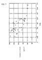
- Fig. 2 shows the spectral distribution in the above described high pressure mercury lamp.
- Fig. 2 shows the spectral distribution in the above described high pressure mercury lamp.
- the figure shows, in the area of visible radiation with wavelengths of roughly 380 to 780 nm effective radiation is obtained.
- in the red range with wavelengths from 600 to 780 nm continuous radiation occurs to a large extent, which in comparison to a lamp containing less than or equal to 0.05 mg/mm 3 of mercury added was clearly multiplied.
- the sealing body 6 has, as is shown in Fig. 3, a essentially cylindrical overall shape. Its end which points towards the emission space is tapered.
- This sealing body 6 is essentially made up of a dielectric component and an electrically conductive component. It is formed, for example, in such a way that a layer 6a with a ratio of molybdenum to silicon dioxide of 0 : 100, a layer 6b with a ratio of molybdenum to silicon dioxide of 25 : 75, a layer 6c with a ratio of molybdenum to silicon dioxide of 50 : 50, a layer 6d with a ratio of molybdenum to silicon dioxide of 75 : 25, and a layer 6e with a ratio of molybdenum to silicon dioxide of 100 : 0, follow one after the other.
- the mixing ratio of molybdenum and silicon dioxide differs in the direction from the mixed layer 6a to the mixed layer 6e gradually or incrementally.
- the property of the sealing body 6 itself thus has a functional gradient.
- One such sealing body is formed, for example, with a length of 22 mm and an outside diameter of 3 mm.
- the layer 6e with a percentage by weight of the silicon dioxide component of 0% and a percentage by weight of the molybdenum component of 100% is located outside the discharge vessel.
- the connection to the outer lead 7 takes place in this area.
- the layer 6a with 100% of the silicon dioxide component is connected to the side tube.
- the ratios of the composition and the number of layers are however not unconditionally limited to the above described numerical values.
- These sealing bodies with a functional gradient are produced by weighing out powders of the electrically conductive component (molybdenum) and the dielectric component (silicon dioxide) while changing of the mixing ratio in the above described manner. More accurately, there are two powders, not mixed powders, since here the other powder at the time is mixed in with 0%. For the sake of simplicity however also these powders are called "mixed powders.” The five mixed powders which have been produced in this way are compressed. This compression takes place in that the above described mixed powders are gradually mixed into a compression casting mold in a sequence in which one of the two components increases quantitatively.
- the sealing body is made by sintering the whole.
- One such sealing body formed of a functional gradient material is disclosed, for example, in published Japanese Patent Application HEI 8-138555.
- molybdenum nickel, tungsten, tantalum, chromium or the like can be used as the electrically conductive component.
- silicon dioxide, aluminum oxide, zirconia, magnesium oxide, silicon carbide, titanium carbide or the like can be used as the dielectric component.
- borosilicate glass powder can be mixed in as the binder.
- the compressive strength can be increased by a sealing body with a functional gradient acting as the hermetically sealed component.
- a / b is established where a is the value of the outside diameter on the end face of the sealing body 6 on the side of the discharge vessel and b is the value of the outside diameter of the side tube in this area, makes it possible to increase the compressive strength even more, as is shown in Fig. 4.
- the reason for establishing a / b in this way is that there are cases in which cracks form at the location at which the end face of the sealing body on the side of the discharge vessel and the side tube of the discharge vessel are welded to one another, although by using the sealing body with a functional gradient, the compressive strength can be sufficiently increased.
- the invention is furthermore characterized in that the ratio a / b is less than or equal to 0.25 where a is the value of the outside diameter on the end face of the sealing body 6 on the side of the discharge vessel and b is the value of the outside diameter of the side tube in this area.
- Fig. 5 shows the compressive strength when the value a / b changes from 0.06 to 0.38.
- the x-axis plots the value of a / b while the y-axis plots the compressive strength. The test was run in the following manner:
- the sealing body 6 was sealed in the silica glass tube such that the dimension of a differs. The dimensions of a and b were measured. Afterwards gas was pressed in from the side of the discharge vessel. The numerical values were read off when destruction occurred.
- the compressive strength is greater at least 130 atm when the value of a / b does not exceed 0.25; this is suitable for the super high-pressure mercury lamp in accordance with the invention.
- the high pressure mercury lamp according to the invention is not limited to only a lamp of the dc operating type, but it can also be a lamp of the ac operating type.
- a side tube part is made which has a sealing body formed of a functional gradient material, which is essentially composed of a dielectric material and a electrically conductive material with a ratio to one another which changes in the lengthwise direction of the sealing body, and which has a dielectric end area and an electrically conductive end area, and in that the sealing body in its dielectric end area is connected to the side tube and in its electrically conductive end area it is connected to the outer lead.
- This arrangement can advantageously eliminate the defect in a foil-seal sealing arrangement, specifically the formation of cracks.
- a mercury lamp with high compressive strength can be devised.
- the object can be advantageously achieved in accordance with the invention by condition a / b ⁇ 0.25 being met, where a is the value of the outside diameter on the end face of the sealing body 6 facing into the discharge vessel and b is the value of the outside diameter of the side tube in this area.
- the compressive strength can be increased even more by this arrangement even if the sealing body has a functional gradient.
Priority Applications (2)
| Application Number | Priority Date | Filing Date | Title |
|---|---|---|---|
| EP99124135A EP1107286A1 (de) | 1999-12-02 | 1999-12-02 | Hochdruck-Quecksilberdampfentladungslampe |
| US09/453,445 US6462471B1 (en) | 1999-12-02 | 1999-12-03 | High pressure mercury lamp provided with a sealing body made of a functional gradient material |
Applications Claiming Priority (2)
| Application Number | Priority Date | Filing Date | Title |
|---|---|---|---|
| EP99124135A EP1107286A1 (de) | 1999-12-02 | 1999-12-02 | Hochdruck-Quecksilberdampfentladungslampe |
| US09/453,445 US6462471B1 (en) | 1999-12-02 | 1999-12-03 | High pressure mercury lamp provided with a sealing body made of a functional gradient material |
Publications (1)
| Publication Number | Publication Date |
|---|---|
| EP1107286A1 true EP1107286A1 (de) | 2001-06-13 |
Family
ID=26153187
Family Applications (1)
| Application Number | Title | Priority Date | Filing Date |
|---|---|---|---|
| EP99124135A Withdrawn EP1107286A1 (de) | 1999-12-02 | 1999-12-02 | Hochdruck-Quecksilberdampfentladungslampe |
Country Status (2)
| Country | Link |
|---|---|
| US (1) | US6462471B1 (de) |
| EP (1) | EP1107286A1 (de) |
Cited By (1)
| Publication number | Priority date | Publication date | Assignee | Title |
|---|---|---|---|---|
| US6597115B2 (en) | 2000-10-31 | 2003-07-22 | Ushiodenki Kabushiki Kaisha | Light source device |
Families Citing this family (1)
| Publication number | Priority date | Publication date | Assignee | Title |
|---|---|---|---|---|
| US7804172B2 (en) * | 2006-01-10 | 2010-09-28 | Halliburton Energy Services, Inc. | Electrical connections made with dissimilar metals |
Citations (8)
| Publication number | Priority date | Publication date | Assignee | Title |
|---|---|---|---|---|
| EP0338637A2 (de) * | 1988-04-21 | 1989-10-25 | Philips Patentverwaltung GmbH | Hochdruck-Quecksilberdampfentladungslampe |
| US4881009A (en) * | 1983-12-05 | 1989-11-14 | Gte Products Corporation | Electrode for high intensity discharge lamps |
| US4959587A (en) * | 1989-01-13 | 1990-09-25 | Venture Lighting International, Inc. | Arc tube assembly |
| DE9206727U1 (de) * | 1992-05-18 | 1992-07-16 | Patent-Treuhand-Gesellschaft Fuer Elektrische Gluehlampen Mbh, 8000 Muenchen, De | |
| EP0650184A1 (de) * | 1992-07-09 | 1995-04-26 | Toto Ltd. | Struktur von abtichtungsteil einer bogenröhre und verfahren zur herstellung derselben |
| JPH0896750A (ja) * | 1994-09-28 | 1996-04-12 | Toshiba Lighting & Technol Corp | 高圧放電灯、放電灯点灯装置および光源装置 |
| JPH08138555A (ja) * | 1994-11-02 | 1996-05-31 | Toto Ltd | 傾斜機能材料の製造方法及び傾斜機能材料を用いた電子管の封止構造 |
| JPH10125284A (ja) * | 1996-10-18 | 1998-05-15 | Toto Ltd | 発光管の封止部構造及び封止部用キャップの製造方法 |
Family Cites Families (4)
| Publication number | Priority date | Publication date | Assignee | Title |
|---|---|---|---|---|
| US5497049A (en) | 1992-06-23 | 1996-03-05 | U.S. Philips Corporation | High pressure mercury discharge lamp |
| JPH1040868A (ja) * | 1996-07-25 | 1998-02-13 | Ushio Inc | 放電ランプ |
| JP3419275B2 (ja) * | 1997-09-30 | 2003-06-23 | ウシオ電機株式会社 | 放電ランプのシール方法 |
| JP2948200B1 (ja) * | 1998-04-08 | 1999-09-13 | ウシオ電機株式会社 | 高圧水銀ランプ |
-
1999
- 1999-12-02 EP EP99124135A patent/EP1107286A1/de not_active Withdrawn
- 1999-12-03 US US09/453,445 patent/US6462471B1/en not_active Expired - Fee Related
Patent Citations (8)
| Publication number | Priority date | Publication date | Assignee | Title |
|---|---|---|---|---|
| US4881009A (en) * | 1983-12-05 | 1989-11-14 | Gte Products Corporation | Electrode for high intensity discharge lamps |
| EP0338637A2 (de) * | 1988-04-21 | 1989-10-25 | Philips Patentverwaltung GmbH | Hochdruck-Quecksilberdampfentladungslampe |
| US4959587A (en) * | 1989-01-13 | 1990-09-25 | Venture Lighting International, Inc. | Arc tube assembly |
| DE9206727U1 (de) * | 1992-05-18 | 1992-07-16 | Patent-Treuhand-Gesellschaft Fuer Elektrische Gluehlampen Mbh, 8000 Muenchen, De | |
| EP0650184A1 (de) * | 1992-07-09 | 1995-04-26 | Toto Ltd. | Struktur von abtichtungsteil einer bogenröhre und verfahren zur herstellung derselben |
| JPH0896750A (ja) * | 1994-09-28 | 1996-04-12 | Toshiba Lighting & Technol Corp | 高圧放電灯、放電灯点灯装置および光源装置 |
| JPH08138555A (ja) * | 1994-11-02 | 1996-05-31 | Toto Ltd | 傾斜機能材料の製造方法及び傾斜機能材料を用いた電子管の封止構造 |
| JPH10125284A (ja) * | 1996-10-18 | 1998-05-15 | Toto Ltd | 発光管の封止部構造及び封止部用キャップの製造方法 |
Non-Patent Citations (3)
| Title |
|---|
| PATENT ABSTRACTS OF JAPAN vol. 1996, no. 08 30 August 1996 (1996-08-30) * |
| PATENT ABSTRACTS OF JAPAN vol. 1996, no. 09 30 September 1996 (1996-09-30) * |
| PATENT ABSTRACTS OF JAPAN vol. 1998, no. 10 31 August 1998 (1998-08-31) * |
Cited By (1)
| Publication number | Priority date | Publication date | Assignee | Title |
|---|---|---|---|---|
| US6597115B2 (en) | 2000-10-31 | 2003-07-22 | Ushiodenki Kabushiki Kaisha | Light source device |
Also Published As
| Publication number | Publication date |
|---|---|
| US6462471B1 (en) | 2002-10-08 |
Similar Documents
| Publication | Publication Date | Title |
|---|---|---|
| US6903509B2 (en) | Ultrahigh pressure discharge lamp of the short arc type with improved metal foil to electrode connection arrangement | |
| JPH01149359A (ja) | 高圧ナトリウム放電ランプ | |
| KR100914112B1 (ko) | 쇼트아크형 방전등 | |
| US6861806B2 (en) | Super-high pressure discharge lamp of the short arc type | |
| US6713957B2 (en) | Super-high pressure discharge lamp of the short arc type | |
| US6462471B1 (en) | High pressure mercury lamp provided with a sealing body made of a functional gradient material | |
| US7560865B2 (en) | Discharge lamp of the short arc type | |
| EP1805784B1 (de) | Hochdruck-gasentladungslampe | |
| US6911775B2 (en) | Short-arc, ultra-high pressure discharge lamp | |
| EP1729325B1 (de) | Ultrahochdruck-Quecksilberlampe | |
| US6940217B2 (en) | Short arc ultra-high pressure discharge lamp | |
| US7002298B2 (en) | Ultra-high pressure discharge lamp | |
| US7973482B2 (en) | High-pressure discharge lamp with halogens | |
| US20060158092A1 (en) | High-Pressure Discharge Lamp | |
| EP1684329A2 (de) | Ultrahochdruck-Quecksilberlampe | |
| JP2000058001A (ja) | 高圧水銀ランプ | |
| JPH11111226A (ja) | ショートアーク型超高圧放電ランプ | |
| JP3447706B2 (ja) | 高圧放電灯およびそのバルブの封止方法 | |
| JP2002251978A (ja) | 高圧水銀ランプ | |
| US20020190668A1 (en) | High-pressure discharge lamp | |
| JP2003282024A (ja) | 高圧放電灯およびそのバルブの封止方法 | |
| JP2005026128A (ja) | 超高圧放電ランプ |
Legal Events
| Date | Code | Title | Description |
|---|---|---|---|
| PUAI | Public reference made under article 153(3) epc to a published international application that has entered the european phase |
Free format text: ORIGINAL CODE: 0009012 |
|
| 17P | Request for examination filed |
Effective date: 20000512 |
|
| AK | Designated contracting states |
Kind code of ref document: A1 Designated state(s): DE FR NL |
|
| AX | Request for extension of the european patent |
Free format text: AL;LT;LV;MK;RO;SI |
|
| AKX | Designation fees paid |
Free format text: DE FR NL |
|
| 17Q | First examination report despatched |
Effective date: 20021203 |
|
| STAA | Information on the status of an ep patent application or granted ep patent |
Free format text: STATUS: THE APPLICATION IS DEEMED TO BE WITHDRAWN |
|
| 18D | Application deemed to be withdrawn |
Effective date: 20030415 |