EP1107164B1 - Kartenlesevorrichtung - Google Patents
Kartenlesevorrichtung Download PDFInfo
- Publication number
- EP1107164B1 EP1107164B1 EP00122578A EP00122578A EP1107164B1 EP 1107164 B1 EP1107164 B1 EP 1107164B1 EP 00122578 A EP00122578 A EP 00122578A EP 00122578 A EP00122578 A EP 00122578A EP 1107164 B1 EP1107164 B1 EP 1107164B1
- Authority
- EP
- European Patent Office
- Prior art keywords
- unit
- slot
- reading unit
- locking element
- locking
- Prior art date
- Legal status (The legal status is an assumption and is not a legal conclusion. Google has not performed a legal analysis and makes no representation as to the accuracy of the status listed.)
- Expired - Lifetime
Links
Images
Classifications
-
- G—PHYSICS
- G06—COMPUTING OR CALCULATING; COUNTING
- G06K—GRAPHICAL DATA READING; PRESENTATION OF DATA; RECORD CARRIERS; HANDLING RECORD CARRIERS
- G06K13/00—Conveying record carriers from one station to another, e.g. from stack to punching mechanism
- G06K13/02—Conveying record carriers from one station to another, e.g. from stack to punching mechanism the record carrier having longitudinal dimension comparable with transverse dimension, e.g. punched card
- G06K13/08—Feeding or discharging cards
- G06K13/0868—Feeding or discharging cards using an arrangement for keeping the feeding or insertion slot of the card station clean of dirt, or to avoid feeding of foreign or unwanted objects into the slot
- G06K13/0875—Feeding or discharging cards using an arrangement for keeping the feeding or insertion slot of the card station clean of dirt, or to avoid feeding of foreign or unwanted objects into the slot the arrangement comprising a shutter for blocking at least part of the card insertion slot
-
- G—PHYSICS
- G06—COMPUTING OR CALCULATING; COUNTING
- G06K—GRAPHICAL DATA READING; PRESENTATION OF DATA; RECORD CARRIERS; HANDLING RECORD CARRIERS
- G06K13/00—Conveying record carriers from one station to another, e.g. from stack to punching mechanism
- G06K13/02—Conveying record carriers from one station to another, e.g. from stack to punching mechanism the record carrier having longitudinal dimension comparable with transverse dimension, e.g. punched card
- G06K13/08—Feeding or discharging cards
-
- G—PHYSICS
- G06—COMPUTING OR CALCULATING; COUNTING
- G06K—GRAPHICAL DATA READING; PRESENTATION OF DATA; RECORD CARRIERS; HANDLING RECORD CARRIERS
- G06K7/00—Methods or arrangements for sensing record carriers, e.g. for reading patterns
- G06K7/0008—General problems related to the reading of electronic memory record carriers, independent of its reading method, e.g. power transfer
Definitions
- the invention relates to a card reading device according to the preamble of patent claim 1
- Card readers are usually attached to a door of a vending machine or the like. They have a slot for a card, which can be closed by a protective flap. There is a reading unit on the back of the wall. It picks up the card during the reading process and contains appropriate scanning means. The reading unit is connected to a control unit which processes the signals coming from the reading unit, e.g. identifies the card and reads the contents of the memory and, if necessary, debits an amount, etc.
- Out DE 30 32 686 A has become known a card reading device in which an approximately trapezoidal console is set against a wall having a hinged door in which a slot for inserting a card is formed.
- a receptacle On the back of the door a receptacle is mounted by screwing into which a cassette-like arrangement of the reading unit is inserted.
- the receptacle includes two spring-biased locking elements to lock the cassette in the receptacle.
- the invention has for its object to provide a card reading device in which the reading unit can be solved in a particularly simple manner without tools by hand from the slot unit. This object is solved by the features of patent claim 1.
- a resiliently biased locking element which cooperates with a locking portion
- an oblong actuating element is arranged laterally of the reading unit with a rear handle for actuating the locking element for the purpose of disengaging from the locking section.
- an actuating element is arranged on each side of the reading unit, and each actuating element acts on a locking element.
- the lugs of the slot unit are preferably received by socket sections of the reading unit.
- the unlocking can be done easily by hand in the rear of the reading unit. Complicated and time-consuming manipulations that may require tools are therefore not required.
- the locking element is associated with the socket and cooperates with a recess of the approach.
- the locking element is integrally formed with a release lever, which is mounted near the rear end pivotally mounted on the reading unit. In order to hold the locking element in operative engagement with the locking portion, in such an embodiment an additional spring would be provided which biases the locking element in the direction of the locking portion.
- the unlocking lever is formed with its locking arm supporting arm as a flat spring, which cooperates with a counter bearing of the reading unit such that the flat spring is bent upon actuation of the release lever outwardly swinging away a locking nose from the recess.
- This embodiment has the further advantage that the handles can be moved towards each other at both ends of the release lever by gripping between thumb and forefinger to accomplish unlocking. It is understood that the described mechanism can also be effective in the inversion, ie, when the operating portions of the release levers move apart from each other, but then the position of the locking recesses in the lugs are on the opposite side of the lever arm.
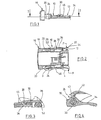
- FIG. 1 shows a reading unit 10, details of which are not intended to be described. It contains a frame-like support 12 for a printed circuit board, not shown, and for a contacting unit (not shown), which engages with a chip card in order to be able to communicate with it.
- the reading unit 10 is shown assembled with a slot unit 16 by two rearwardly projecting lugs 18, 20 in socket sections 22, 24 are inserted.
- a certain distance which is normally occupied by the wall or the door of a machine or the like.
- the slot unit is usually arranged at the front of the wall, with the lugs 18, 20 being guided through an opening to the rear.
- the lugs 18, 20 are in the rear area in cross section rectangular and hollow. They each have a locking recess on the outside into which a locking nose 28 of an unlocking lever 30 engages.
- the lugs 18, 20 engage approximately fitting in the socket sections 22, 24, whose cross-section is correspondingly shaped complementarily.
- the unlocking lever 30 are pivotally mounted about an axis 32 and have a first arm, which is designed as a handle 34.
- the other arm 36 is longer and thinner and extends to the locking lug 28, which is integrally formed with the arm 36.
- the lever 30 is made of a suitable flexible plastic material.
- a projection 40 of the lever 28 abuts against a stop 42 which is connected to the support of the reading unit 10.
- the arrangement of the projection 40 which extends radially away from the axis of rotation 32, is such that the locking lug 28 is biased in the direction of the recess 26.
- This bias is achieved in that the arm 36 of the lever 30 is formed as an elongate spring element and is still under tension when the nose 28 engages completely in the recess 26. If the slot unit with the lugs 18, 20 inserted into the socket sections 22, 24, the nose 28 runs on the inside of the associated approach 18 or 20, after it was previously deflected over its ramp-like portion 44 inwardly until the nose 28 in the Recess 26 snaps. In this way, reading unit 10 and slot unit 16 are locked together.
- a force in the direction F is applied to the handle 34 by grasping the handle 34 between the thumb and forefinger.
- the lever arm 36 bears against a fixed stop 52 and is bent in the area between stop 52 and axis of rotation 32 to the outside, wherein the bend is further enhanced by the fact that on the outside of the otherwise flat arm 36, a rib 46 is formed through which is ensured that in particular the area of the lever arm 36 near the fixed point or stop 52 is bent particularly strong outwards.
- the locking lug 28 moves out of the recess 26 and the reading unit 10 can be removed from the slot unit 16, which is suitably connected to the wall, not shown, of a machine or the like.
Landscapes
- Engineering & Computer Science (AREA)
- Physics & Mathematics (AREA)
- General Physics & Mathematics (AREA)
- Theoretical Computer Science (AREA)
- Artificial Intelligence (AREA)
- Computer Vision & Pattern Recognition (AREA)
- Lock And Its Accessories (AREA)
- Holo Graphy (AREA)
- Credit Cards Or The Like (AREA)
- Mounting Of Printed Circuit Boards And The Like (AREA)
Description
- Die Erfindung bezieht sich auf eine Kartenlesevorrichtung nach dem Oberbegriff des Patentanspruchs 1
- Kartenlesevorrichtungen sind üblicherweise an einer Tür eines Automaten oder dergleichen angebracht. Sie weisen einen Einsteckschlitz für eine Karte auf, der durch eine Schutzklappe verschlossen sein kann. Auf der Rückseite der Wand ist eine Leseeinheit angebracht. Sie nimmt die Karte während des Leseprozesses auf und enthält entsprechende Abtastmittel. Die Leseeinheit ist mit einer Steuereinheit verbunden, welche die von der Leseeinheit kommenden Signale verarbeitet, z.B. die Karte identifiz ert und den Speicherinhalt abliest und ggf. einen Betrag abbucht usw.
- Aus
DE 197 38 412 ist eine Kartenlesevorrichtung bekannt geworden, bei der eine getrennte Schlitzeinheit vorgesehen ist, die an der Vorderseite der Wand montiert wird und mit sich nach hinten erstreckenden Ansätzen durch die Öffnung in der Wand hindurch geführt ist. Die Ansätze greifen in Fassungsabschnitte eines Trägers für die Leseeinheit und werden über eine lösbare, ein federnd vorgespanntes Verriegelungselement aufweisende Schnappverbindung verbunden werden. Für den Ausbau der Leseeinheit zwecks Austausch oder Wartung braucht sie lediglich von dem rückwärtigen Teil der Schlitzeinheit gelöst zu werden. Die Schlitzeinheit kann an der Wand verbleiben. - Aus
DE 30 32 686 A ist eine Kartenlesevorrichtung bekannt geworden, bei der eine annähernd trapezoide Konsole gegen eine Wand gesetzt ist die eine aufklappbare Tür aufweist, in der ein Schlitz zum Einschieben einer Karte geformt ist. An der Türrückseite ist durch Verschraubung eine Aufnahme angebracht, in die eine kassettenartige Anordnung der Leseeinheit einschiebbar ist. Die Aufnahme enthält zwei federvorgespannte Verriegelungselemente, um die Kassette in der Aufnahme zu verriegeln. - Der Erfindung liegt die Aufgabe zugrunde, eine Kartenlesevorrichtung zu schaffen, bei der die Leseeinheit auf besonders einfache Weise ohne Werkzeuge von Hand von der Schlitzeinheit gelöst werden kann. Diese Aufgabe wird durch die Merkmale des Patentanspruchs 1 gelöst.
- Bei der Erfindung wirkt wie im bekannten Fall zwischen mindestens einem Ansatz und mindestens einem mit dem Ansatz teleskopisch zusammenwirkenden Abschnitt der Leseeinheit ein federnd vorgespanntes Verriegelungselement, das mit einem Verriegelungsabschnitt zusammenwirkt.
- Erfindungsgemäß ist seitlich der Leseeinheit ist ein längliches Betätigungselement angeordnet mit einer hinteren Handhabe zur Betätigung des Verriegelungselements zwecks Außereingriffbringens mit dem Verriegelungsabschnitt. Vorzugsweise ist auf jeder Seite der Leseeinheit ein Betätigungselement angeordnet, und jedes Betätigungselement wirkt auf ein Verriegelungselement. Die Ansätze der Schlitzeinheit werden vorzugsweise von Fassungsabschnitten der Leseeinheit aufgenommen.
- Bei der Erfindung kann die Entriegelung auf einfache Weise von Hand im hinteren Bereich der Leseeinheit vorgenommen werden. Komplizierte und zeitraubende Manipulationen, die eventuell auch Werkzeuge erfordern, sind mithin nicht erforderlich.
- Es sind verschiedene Verriegelungs- bzw. Entriegelungsmechanismen denkbar. Bei einer Ausgestaltung der Erfindung ist das Verriegelungselement der Fassung zugeordnet und wirkt mit einer Ausnehmung des Ansatzes zusammen. Nach einer weiteren Ausgestaltung der Erfindung ist das Verriegelungselement einteilig mit einem Entriegelungshebel geformt, der nahe dem hinteren Ende schwenkbar an der Leseeinheit gelagert ist. Um das Verriegelungselement in wirksamem Eingriff mit dem Verriegelungsabschnitt zu halten, wäre bei einer solchen Ausführungsform eine zusätzliche Feder vorzusehen, welche das Verriegelungselement in Richtung Verriegelungsabschnitt vorspannt. Eine solche Feder kann in Fortfall kommen, wenn nach einer weiteren Ausgestaltung der Erfindung der Entriegelungshebel mit seinem das Verriegelungselement tragenden Arm als Flachfeder ausgebildet ist, die mit einem Gegenlager der Leseeinheit derart zusammenwirkt, dass die Flachfeder bei Betätigung des Entriegelungshebels nach außen gebogen wird unter Wegschwenken einer Verriegelungsnase aus der Ausnehmung. Diese Ausgestaltung hat den weiteren Vorteil, dass die Handhaben an beiden Enden der Entriegelungshebel durch Ergreifen zwischen Daumen und Zeigefinger aufeinander zu bewegt werden können, um eine Entriegelung zu bewerkstelligen. Es versteht sich, dass der beschriebene Mechanismus auch in der Umkehrung wirksam sein kann, d.h. bei Auseinanderbewegen der Betätigungsabschnitte der Entriegelungshebel voneinander fort, wobei dann jedoch die Lage der Verriegelungsausnehmungen in den Ansätzen auf der gegenüberliegenden Seite des Hebelarms liegen.
- Es ist auch denkbar, das Betätigungselement um seine Längsachse drehbar oder in einer anderen Ebene schwenkbar zu lagern, um das Verriegelungselement zu betätigen.
- Die Erfindung wird nachfolgend anhand eines in Zeichnungen dargestellten Ausführungsbeispiels näher erläutert.
- Fig. 1
- zeigt schematisch in Seitenansicht eine Schlitzeinheit und eine Leseeinheit nach der Erfindung.
- Fig. 2
- zeigt einen Schnitt durch die Darstellung nach Fig. 1 entlang der Linie 2-2.
- Fig. 3
- zeigt vergrößert die Einzelheit 3 der Darstellung nach Fig. 2.
- Fig. 4
- zeigt vergrößert die Einzelheit 4 nach Fig. 2.
- In Fig. 1 ist eine Leseeinheit 10 zu erkennen, von der Einzelheiten nicht beschrieben werden sollen. Sie enthält einen rahmenartigen Träger 12 für eine nicht gezeigte Leiterplatte und für eine Kontaktierungseinheit (nicht gezeigt), welche mit einer Chipkarte in Eingriff tritt, um mit dieser kommunizieren zu können. In Fig. 1 und 2 ist die Leseeinheit 10 mit einer Schlitzeinheit 16 zusammengebaut gezeigt, indem zwei nach hinten ragende Ansätze 18, 20 in Fassungsabschnitte 22, 24 eingesteckt sind. Wie aus Fig. 1 und 2 zu erkennen, ist zwischen der Rückseite der Schlitzeinheit 16 und den Fassungsabschnitten 22, 24 ein gewisser Abstand, der normalerweise von der Wand oder der Tür eines Automaten oder dergleichen eingenommen wird. Die Schlitzeinheit wird üblicherweise an der Vorderseite der Wand angeordnet, wobei die Ansätze 18, 20 durch eine Öffnung hindurch nach hinten geführt sind.
- Die Ansätze 18, 20 sind im hinteren Bereich im Querschnitt rechteckig und hohl. Sie weisen an der Außenseite jeweils eine Verriegelungsausnehmung auf, in welche eine Verriegelungsnase 28 eines Entriegelungshebels 30 eingreift. Die Ansätze 18, 20 greifen annähernd passend in die Fassungsabschnitte 22, 24 ein, deren Querschnitt dementsprechend komplementär geformt ist.
- Die Entriegelungshebel 30 sind um eine Achse 32 schwenkbar gelagert und weisen einen ersten Arm auf, der als Handhabe 34 ausgebildet ist. Der andere Arm 36 ist länger ausgebildet und dünner und reicht bis zur Verriegelungsnase 28, die einteilig mit dem Arm 36 geformt ist. Der Hebel 30 besteht aus einem geeigneten flexiblen Kunststoffmaterial.
- Wie besser aus Fig. 4 hervorgeht, liegt ein Vorsprung 40 des Hebels 28 gegen einen Anschlag 42 an, der mit dem Träger der Leseeinheit 10 verbunden ist. Die Anordnung des Vorsprungs 40, der sich radial von der Drehachse 32 fort erstreckt, ist derart, dass die Verriegelungsnase 28 in Richtung Ausnehmung 26 vorgespannt ist. Diese Vorspannung wird dadurch erzielt, dass der Arm 36 des Hebels 30 als längliches Federelement ausgebildet ist und auch dann noch unter Spannung steht, wenn die Nase 28 vollständig in die Ausnehmung 26 eingreift. Wird die Schlitzeinheit mit den Ansätzen 18, 20 in die Fassungsabschnitte 22, 24 eingesteckt, läuft die Nase 28 an der Innenseite des zugeordneten Ansatzes 18 oder 20, nachdem sie zuvor über ihren rampenartigen Abschnitt 44 nach innen ausgelenkt wurde, bis die Nase 28 in die Ausnehmung 26 einschnappt. Auf diese Weise sind Leseeinheit 10 und Schlitzeinheit 16 verriegelt miteinander verbunden.
- Soll eine Demontage erfolgen, wird durch Ergreifen der Handhaben 34 zwischen Daumen und Zeigefinger eine Kraft in Richtung F auf die Handhaben 34 ausgeübt. Der Hebelarm 36 legt sich dabei gegen einen festen Anschlag 52 und wird in dem Bereich zwischen Anschlag 52 und Drehachse 32 nach außen gebogen, wobei die Biegung noch dadurch verstärkt wird, dass an der Außenseite des ansonsten flachen Arms 36 eine Rippe 46 geformt ist, durch welche sicher gestellt ist, dass insbesondere der Bereich des Hebelarms 36 nahe dem Festpunkt oder Anschlag 52 besonders stark nach außen gebogen wird. Dadurch bewegt sich die Verriegelungsnase 28 aus der Ausnehmung 26 hinaus und die Leseeinheit 10 kann von der Schlitzeinheit 16 entfernt werden, welche in geeigneter Art und Weise mit der nicht gezeigten Wand eines Automaten oder dergleichen verbunden ist.
Claims (7)
- Kartenlesevorrichtung, die an einer Wand angebracht werden kann, mit einer Schlitzeinheit (16), die einen Einsteckschlitz für eine Karte aufweist, in der eine Schlitzklappe verschwenkbar gelagert sein kann und die an der Wand befestigt ist und sich beidseitig der Wandöffnung erstreckt und einer zum Einsteckschlitz ausgerichteten Leseeinheit (10), in die die Karte eingeführt wird, wenn sie in den Einsteckschlitz eingeschoben wird und die einen Träger (12) aufweist, der an der Rückseite der Schlitzeinheit (16) angebracht ist und einer mit der Leseeinheit (10) verbundenen Steuereinheit, wobei die Schlitzeinheit (16) zwei sich durch die Wandöffnung erstreckende Ansätze (18, 20) aufweist, welche mit dem Träger (12) der Leseeinheit (10) eine lösbare Schnappverbindung bilden, wobei zwischen mindestens einem Ansatz (18, 20) und einem mit dem Ansatz (18, 20) teleskopisch zusammenwirkenden Abschnitt (22, 24) der Leseeinheit (10) ein federnd vorgespanntes Verriegelungselement (28) wirkt, das mit einem Verriegelungsabschnitt (26) zusammenwirkt, dadurch gekennzeichnet, daß seitlich an der Leseeinheit (10) ein längliches Betätigungselement (30) angeordnet ist mit einer hinteren Handhabe (34) zur Betätigung des Verriegelungselements zwecks Außereingriffbringens mit dem Verriegelungsabschnitt (26).
- Lesevorrichtung nach Anspruch 1, dadurch gekennzeichnet, dass auf jeder Seite der Leseeinheit (10) ein Betätigungselement (30) angeordnet ist und jedes Betätigungselement (30) mit einem Verriegelungselement (28) für einen Ansatz (18, 20) bzw. einen Abschnitt (24, 26) der Leseeinheit (10) zusammenwirkt.
- Kartenlesevorrichtung nach Anspruch 1 oder 2, dadurch gekennzeichnet, dass das Verriegelungselement (28) mit einer Ausnehmung (26) des Ansatzes (18, 20) zusammenwirkt.
- Kartenlesevorrichtung nach einem der Ansprüche 1 bis 3, dadurch gekennzeichnet, dass das Verriegelungselement (28) einteilig mit einem Entriegelungshebel geformt ist, der nahe dem hinteren Ende schwenkbar (32) oder um seine Längsachse drehbar an der Leseeinheit (10) gelagert ist.
- Kartenlesevorrichtung nach Anspruch 4, dadurch gekennzeichnet, dass der Entriegelungshebel mit seinem das Verriegelungselement (28) tragenden Arm als längliche Feder ausgebildet ist, die mit einem Gegenlager (52) der Leseeinheit (10) derart zusammenwirkt, dass die Feder bei Betätigung der Handhabe nach außen gebogen wird unter Wegschwenken des Verriegelungselements (28) aus der Ausnehmung.
- Kartenlesevorrichtung nach Anspruch 5, dadurch gekennzeichnet, dass das Verriegelungselement (28) von einer Verriegelungsnase gebildet ist, die zum freien Ende hin eine Auflauframpe (44) aufweist.
- Kartenlesevorrichtung nach Anspruch 5 oder 6, dadurch gekennzeichnet, dass die Vorspannung durch den federnden Arm des Entriegelungshebels erfolgt, der über zwei Anschläge (40, 42) an einem Verschwenken in der entgegengesetzten Richtung gehindert ist.
Applications Claiming Priority (2)
| Application Number | Priority Date | Filing Date | Title |
|---|---|---|---|
| DE19959464A DE19959464C2 (de) | 1999-12-10 | 1999-12-10 | Kartenlesevorrichtung |
| DE19959464 | 1999-12-10 |
Publications (3)
| Publication Number | Publication Date |
|---|---|
| EP1107164A2 EP1107164A2 (de) | 2001-06-13 |
| EP1107164A3 EP1107164A3 (de) | 2002-05-29 |
| EP1107164B1 true EP1107164B1 (de) | 2007-08-22 |
Family
ID=7932058
Family Applications (1)
| Application Number | Title | Priority Date | Filing Date |
|---|---|---|---|
| EP00122578A Expired - Lifetime EP1107164B1 (de) | 1999-12-10 | 2000-10-17 | Kartenlesevorrichtung |
Country Status (4)
| Country | Link |
|---|---|
| EP (1) | EP1107164B1 (de) |
| AT (1) | ATE371222T1 (de) |
| DE (2) | DE19959464C2 (de) |
| ES (1) | ES2289989T3 (de) |
Families Citing this family (1)
| Publication number | Priority date | Publication date | Assignee | Title |
|---|---|---|---|---|
| DE20314536U1 (de) | 2003-09-19 | 2003-11-13 | STOCKO Contact GmbH & Co. KG, 42327 Wuppertal | PCMCIA-Chipkartenleser und Blende für PCMCIA-Chipkartenleser |
Family Cites Families (5)
| Publication number | Priority date | Publication date | Assignee | Title |
|---|---|---|---|---|
| US4258253A (en) * | 1979-11-07 | 1981-03-24 | Fisher Charles R | Cartridge assembly for data-sensing system |
| DE8712368U1 (de) * | 1987-09-11 | 1987-10-29 | Siemens AG, 1000 Berlin und 8000 München | Gehäuse für einen Chipkartenleser |
| US5398157A (en) * | 1993-04-13 | 1995-03-14 | Kingston Technology Corporation | Snap-in mounting bracket for a computer memory device |
| TW404583U (en) * | 1997-06-09 | 2000-09-01 | Whitaker Corp | Panel mounted smart card connector |
| DE19738412C2 (de) * | 1997-09-03 | 2003-01-02 | Nat Rejectors Gmbh | Kartenlesevorrichtung |
-
1999
- 1999-12-10 DE DE19959464A patent/DE19959464C2/de not_active Expired - Fee Related
-
2000
- 2000-10-17 AT AT00122578T patent/ATE371222T1/de not_active IP Right Cessation
- 2000-10-17 DE DE50014582T patent/DE50014582D1/de not_active Expired - Fee Related
- 2000-10-17 EP EP00122578A patent/EP1107164B1/de not_active Expired - Lifetime
- 2000-10-17 ES ES00122578T patent/ES2289989T3/es not_active Expired - Lifetime
Also Published As
| Publication number | Publication date |
|---|---|
| EP1107164A2 (de) | 2001-06-13 |
| EP1107164A3 (de) | 2002-05-29 |
| DE19959464A1 (de) | 2001-06-21 |
| ES2289989T3 (es) | 2008-02-16 |
| DE19959464C2 (de) | 2003-10-23 |
| DE50014582D1 (de) | 2007-10-04 |
| ATE371222T1 (de) | 2007-09-15 |
Similar Documents
| Publication | Publication Date | Title |
|---|---|---|
| DE69417102T2 (de) | Vorrichtung zum Befestigen einer Visierscheibe an einem Helm | |
| DE60101923T2 (de) | Kabelkanalsystemscharnieranordnung | |
| EP1890043B1 (de) | Luftdurchtrittsvorrichtung mit einer verbesserten Zugänglichkeit der Filtermatte | |
| DE3885321T2 (de) | Lese- und Schreibvorrichtung für IC-Karten. | |
| DE102016123831B3 (de) | Computergehäuse und Computersystem | |
| EP2948314B1 (de) | Selbstfärbestempel | |
| DE3905647C2 (de) | ||
| EP0021406A1 (de) | Filmkassette mit einem Fenster zum Einbelichten von Daten | |
| DE202006010888U1 (de) | Luftdurchtrittsvorrichtung | |
| EP0215398B1 (de) | Verschwenkbare Beschriftungsblende | |
| EP0831001A1 (de) | Hängerunge | |
| EP1914780B1 (de) | Sicherungslasttrennschalter und Verriegelungseinrichtung für einen Sicherungslasttrennschalter | |
| DE69004331T2 (de) | Schreibmaschinenfarbbandkassette. | |
| DE69709990T2 (de) | Betätigungsvorrichtung zum Öffnen einer Fahrzeugtür | |
| DE60126361T2 (de) | Elektronische Vorrichtung mit abnehmbarer Bedienungsblende | |
| DE19738412C2 (de) | Kartenlesevorrichtung | |
| DE19959464C2 (de) | Kartenlesevorrichtung | |
| DE60100223T2 (de) | Elektrische Steckeranordnung mit einer Bajonettverschlussverbindung | |
| EP0408544B1 (de) | Relais | |
| DE10115400B4 (de) | Toplader-Waschmaschine mit einer Wäschetrommel im Maschinengehäuse | |
| DE19630414A1 (de) | (Speicher) programmierbare Steuerung | |
| DE69608870T2 (de) | Vorrichtung zum Vermeiden von falscher Verriegelung einer Abdeckung eines Verbinders und elektrische Verbindungsdose mit dieser Vorrichtung | |
| DE4412923C1 (de) | Elektrischer Schalter mit Tastkopf | |
| DE29722178U1 (de) | Bezeichnungsträger für elektrische Leiter | |
| EP3425145B1 (de) | Fallenverschluss mit betriebssicherer betätigung |
Legal Events
| Date | Code | Title | Description |
|---|---|---|---|
| PUAI | Public reference made under article 153(3) epc to a published international application that has entered the european phase |
Free format text: ORIGINAL CODE: 0009012 |
|
| AK | Designated contracting states |
Kind code of ref document: A2 Designated state(s): AT BE CH CY DE DK ES FI FR GB GR IE IT LI LU MC NL PT SE |
|
| AX | Request for extension of the european patent |
Free format text: AL;LT;LV;MK;RO;SI |
|
| PUAL | Search report despatched |
Free format text: ORIGINAL CODE: 0009013 |
|
| RIC1 | Information provided on ipc code assigned before grant |
Free format text: 7G 06K 7/01 A, 7G 06K 7/00 B |
|
| AK | Designated contracting states |
Kind code of ref document: A3 Designated state(s): AT BE CH CY DE DK ES FI FR GB GR IE IT LI LU MC NL PT SE |
|
| AX | Request for extension of the european patent |
Free format text: AL;LT;LV;MK;RO;SI |
|
| 17P | Request for examination filed |
Effective date: 20021012 |
|
| AKX | Designation fees paid |
Designated state(s): AT BE CH CY DE DK ES FI FR GB GR IE IT LI LU MC NL PT SE |
|
| 17Q | First examination report despatched |
Effective date: 20061117 |
|
| GRAP | Despatch of communication of intention to grant a patent |
Free format text: ORIGINAL CODE: EPIDOSNIGR1 |
|
| GRAS | Grant fee paid |
Free format text: ORIGINAL CODE: EPIDOSNIGR3 |
|
| GRAA | (expected) grant |
Free format text: ORIGINAL CODE: 0009210 |
|
| AK | Designated contracting states |
Kind code of ref document: B1 Designated state(s): AT BE CH CY DE DK ES FI FR GB GR IE IT LI LU MC NL PT SE |
|
| REG | Reference to a national code |
Ref country code: GB Ref legal event code: FG4D Free format text: NOT ENGLISH |
|
| GBT | Gb: translation of ep patent filed (gb section 77(6)(a)/1977) |
Effective date: 20070822 |
|
| REG | Reference to a national code |
Ref country code: CH Ref legal event code: EP |
|
| PGFP | Annual fee paid to national office [announced via postgrant information from national office to epo] |
Ref country code: ES Payment date: 20070919 Year of fee payment: 8 |
|
| REG | Reference to a national code |
Ref country code: IE Ref legal event code: FG4D Free format text: LANGUAGE OF EP DOCUMENT: GERMAN |
|
| REF | Corresponds to: |
Ref document number: 50014582 Country of ref document: DE Date of ref document: 20071004 Kind code of ref document: P |
|
| ET | Fr: translation filed | ||
| PG25 | Lapsed in a contracting state [announced via postgrant information from national office to epo] |
Ref country code: NL Free format text: LAPSE BECAUSE OF FAILURE TO SUBMIT A TRANSLATION OF THE DESCRIPTION OR TO PAY THE FEE WITHIN THE PRESCRIBED TIME-LIMIT Effective date: 20070822 Ref country code: FI Free format text: LAPSE BECAUSE OF FAILURE TO SUBMIT A TRANSLATION OF THE DESCRIPTION OR TO PAY THE FEE WITHIN THE PRESCRIBED TIME-LIMIT Effective date: 20070822 |
|
| NLV1 | Nl: lapsed or annulled due to failure to fulfill the requirements of art. 29p and 29m of the patents act | ||
| REG | Reference to a national code |
Ref country code: ES Ref legal event code: FG2A Ref document number: 2289989 Country of ref document: ES Kind code of ref document: T3 |
|
| REG | Reference to a national code |
Ref country code: IE Ref legal event code: FD4D |
|
| BERE | Be: lapsed |
Owner name: NATIONAL REJECTORS, INC. G.M.B.H. Effective date: 20071031 |
|
| PG25 | Lapsed in a contracting state [announced via postgrant information from national office to epo] |
Ref country code: GR Free format text: LAPSE BECAUSE OF FAILURE TO SUBMIT A TRANSLATION OF THE DESCRIPTION OR TO PAY THE FEE WITHIN THE PRESCRIBED TIME-LIMIT Effective date: 20071123 Ref country code: DK Free format text: LAPSE BECAUSE OF FAILURE TO SUBMIT A TRANSLATION OF THE DESCRIPTION OR TO PAY THE FEE WITHIN THE PRESCRIBED TIME-LIMIT Effective date: 20070822 |
|
| PGFP | Annual fee paid to national office [announced via postgrant information from national office to epo] |
Ref country code: FR Payment date: 20070927 Year of fee payment: 8 Ref country code: GB Payment date: 20071002 Year of fee payment: 8 |
|
| PG25 | Lapsed in a contracting state [announced via postgrant information from national office to epo] |
Ref country code: IE Free format text: LAPSE BECAUSE OF FAILURE TO SUBMIT A TRANSLATION OF THE DESCRIPTION OR TO PAY THE FEE WITHIN THE PRESCRIBED TIME-LIMIT Effective date: 20070822 Ref country code: MC Free format text: LAPSE BECAUSE OF NON-PAYMENT OF DUE FEES Effective date: 20071031 Ref country code: PT Free format text: LAPSE BECAUSE OF FAILURE TO SUBMIT A TRANSLATION OF THE DESCRIPTION OR TO PAY THE FEE WITHIN THE PRESCRIBED TIME-LIMIT Effective date: 20080122 |
|
| PGFP | Annual fee paid to national office [announced via postgrant information from national office to epo] |
Ref country code: DE Payment date: 20071214 Year of fee payment: 8 |
|
| REG | Reference to a national code |
Ref country code: CH Ref legal event code: PL |
|
| PLBE | No opposition filed within time limit |
Free format text: ORIGINAL CODE: 0009261 |
|
| STAA | Information on the status of an ep patent application or granted ep patent |
Free format text: STATUS: NO OPPOSITION FILED WITHIN TIME LIMIT |
|
| PG25 | Lapsed in a contracting state [announced via postgrant information from national office to epo] |
Ref country code: SE Free format text: LAPSE BECAUSE OF FAILURE TO SUBMIT A TRANSLATION OF THE DESCRIPTION OR TO PAY THE FEE WITHIN THE PRESCRIBED TIME-LIMIT Effective date: 20071122 |
|
| 26N | No opposition filed |
Effective date: 20080526 |
|
| PG25 | Lapsed in a contracting state [announced via postgrant information from national office to epo] |
Ref country code: CH Free format text: LAPSE BECAUSE OF NON-PAYMENT OF DUE FEES Effective date: 20071031 Ref country code: LI Free format text: LAPSE BECAUSE OF NON-PAYMENT OF DUE FEES Effective date: 20071031 |
|
| PG25 | Lapsed in a contracting state [announced via postgrant information from national office to epo] |
Ref country code: BE Free format text: LAPSE BECAUSE OF NON-PAYMENT OF DUE FEES Effective date: 20071031 |
|
| PG25 | Lapsed in a contracting state [announced via postgrant information from national office to epo] |
Ref country code: AT Free format text: LAPSE BECAUSE OF NON-PAYMENT OF DUE FEES Effective date: 20071017 |
|
| GBPC | Gb: european patent ceased through non-payment of renewal fee |
Effective date: 20081017 |
|
| REG | Reference to a national code |
Ref country code: FR Ref legal event code: ST Effective date: 20090630 |
|
| PG25 | Lapsed in a contracting state [announced via postgrant information from national office to epo] |
Ref country code: CY Free format text: LAPSE BECAUSE OF FAILURE TO SUBMIT A TRANSLATION OF THE DESCRIPTION OR TO PAY THE FEE WITHIN THE PRESCRIBED TIME-LIMIT Effective date: 20070822 |
|
| PG25 | Lapsed in a contracting state [announced via postgrant information from national office to epo] |
Ref country code: LU Free format text: LAPSE BECAUSE OF NON-PAYMENT OF DUE FEES Effective date: 20071017 Ref country code: IT Free format text: LAPSE BECAUSE OF NON-PAYMENT OF DUE FEES Effective date: 20071017 Ref country code: DE Free format text: LAPSE BECAUSE OF NON-PAYMENT OF DUE FEES Effective date: 20090501 |
|
| PG25 | Lapsed in a contracting state [announced via postgrant information from national office to epo] |
Ref country code: FR Free format text: LAPSE BECAUSE OF NON-PAYMENT OF DUE FEES Effective date: 20081031 |
|
| PG25 | Lapsed in a contracting state [announced via postgrant information from national office to epo] |
Ref country code: GB Free format text: LAPSE BECAUSE OF NON-PAYMENT OF DUE FEES Effective date: 20081017 |
|
| REG | Reference to a national code |
Ref country code: ES Ref legal event code: FD2A Effective date: 20081018 |
|
| PG25 | Lapsed in a contracting state [announced via postgrant information from national office to epo] |
Ref country code: ES Free format text: LAPSE BECAUSE OF NON-PAYMENT OF DUE FEES Effective date: 20081018 |
|
| PGFP | Annual fee paid to national office [announced via postgrant information from national office to epo] |
Ref country code: IT Payment date: 20071207 Year of fee payment: 8 |
|
| PGRI | Patent reinstated in contracting state [announced from national office to epo] |
Ref country code: IT Effective date: 20110616 |
|
| PGRI | Patent reinstated in contracting state [announced from national office to epo] |
Ref country code: IT Effective date: 20110616 |