EP1106962A2 - Verfahren und Vorrichtung zur Bestimmung der relativen Lage zweier Fahrzeugteile - Google Patents
Verfahren und Vorrichtung zur Bestimmung der relativen Lage zweier Fahrzeugteile Download PDFInfo
- Publication number
- EP1106962A2 EP1106962A2 EP00123959A EP00123959A EP1106962A2 EP 1106962 A2 EP1106962 A2 EP 1106962A2 EP 00123959 A EP00123959 A EP 00123959A EP 00123959 A EP00123959 A EP 00123959A EP 1106962 A2 EP1106962 A2 EP 1106962A2
- Authority
- EP
- European Patent Office
- Prior art keywords
- seal
- parts
- determining
- magnetic field
- course
- Prior art date
- Legal status (The legal status is an assumption and is not a legal conclusion. Google has not performed a legal analysis and makes no representation as to the accuracy of the status listed.)
- Granted
Links
- 238000000034 method Methods 0.000 title claims abstract description 9
- 239000000696 magnetic material Substances 0.000 claims description 2
- 230000008878 coupling Effects 0.000 description 4
- 238000010168 coupling process Methods 0.000 description 4
- 238000005859 coupling reaction Methods 0.000 description 4
- 239000011248 coating agent Substances 0.000 description 1
- 238000000576 coating method Methods 0.000 description 1
- 230000007774 longterm Effects 0.000 description 1
- 230000005415 magnetization Effects 0.000 description 1
- 238000004519 manufacturing process Methods 0.000 description 1
Images
Classifications
-
- G—PHYSICS
- G01—MEASURING; TESTING
- G01D—MEASURING NOT SPECIALLY ADAPTED FOR A SPECIFIC VARIABLE; ARRANGEMENTS FOR MEASURING TWO OR MORE VARIABLES NOT COVERED IN A SINGLE OTHER SUBCLASS; TARIFF METERING APPARATUS; MEASURING OR TESTING NOT OTHERWISE PROVIDED FOR
- G01D5/00—Mechanical means for transferring the output of a sensing member; Means for converting the output of a sensing member to another variable where the form or nature of the sensing member does not constrain the means for converting; Transducers not specially adapted for a specific variable
- G01D5/12—Mechanical means for transferring the output of a sensing member; Means for converting the output of a sensing member to another variable where the form or nature of the sensing member does not constrain the means for converting; Transducers not specially adapted for a specific variable using electric or magnetic means
- G01D5/25—Selecting one or more conductors or channels from a plurality of conductors or channels, e.g. by closing contacts
- G01D5/251—Selecting one or more conductors or channels from a plurality of conductors or channels, e.g. by closing contacts one conductor or channel
- G01D5/2515—Selecting one or more conductors or channels from a plurality of conductors or channels, e.g. by closing contacts one conductor or channel with magnetically controlled switches, e.g. by movement of a magnet
-
- G—PHYSICS
- G01—MEASURING; TESTING
- G01B—MEASURING LENGTH, THICKNESS OR SIMILAR LINEAR DIMENSIONS; MEASURING ANGLES; MEASURING AREAS; MEASURING IRREGULARITIES OF SURFACES OR CONTOURS
- G01B7/00—Measuring arrangements characterised by the use of electric or magnetic techniques
- G01B7/003—Measuring arrangements characterised by the use of electric or magnetic techniques for measuring position, not involving coordinate determination
-
- G—PHYSICS
- G01—MEASURING; TESTING
- G01D—MEASURING NOT SPECIALLY ADAPTED FOR A SPECIFIC VARIABLE; ARRANGEMENTS FOR MEASURING TWO OR MORE VARIABLES NOT COVERED IN A SINGLE OTHER SUBCLASS; TARIFF METERING APPARATUS; MEASURING OR TESTING NOT OTHERWISE PROVIDED FOR
- G01D5/00—Mechanical means for transferring the output of a sensing member; Means for converting the output of a sensing member to another variable where the form or nature of the sensing member does not constrain the means for converting; Transducers not specially adapted for a specific variable
- G01D5/12—Mechanical means for transferring the output of a sensing member; Means for converting the output of a sensing member to another variable where the form or nature of the sensing member does not constrain the means for converting; Transducers not specially adapted for a specific variable using electric or magnetic means
- G01D5/14—Mechanical means for transferring the output of a sensing member; Means for converting the output of a sensing member to another variable where the form or nature of the sensing member does not constrain the means for converting; Transducers not specially adapted for a specific variable using electric or magnetic means influencing the magnitude of a current or voltage
- G01D5/142—Mechanical means for transferring the output of a sensing member; Means for converting the output of a sensing member to another variable where the form or nature of the sensing member does not constrain the means for converting; Transducers not specially adapted for a specific variable using electric or magnetic means influencing the magnitude of a current or voltage using Hall-effect devices
- G01D5/145—Mechanical means for transferring the output of a sensing member; Means for converting the output of a sensing member to another variable where the form or nature of the sensing member does not constrain the means for converting; Transducers not specially adapted for a specific variable using electric or magnetic means influencing the magnitude of a current or voltage using Hall-effect devices influenced by the relative movement between the Hall device and magnetic fields
-
- G—PHYSICS
- G01—MEASURING; TESTING
- G01D—MEASURING NOT SPECIALLY ADAPTED FOR A SPECIFIC VARIABLE; ARRANGEMENTS FOR MEASURING TWO OR MORE VARIABLES NOT COVERED IN A SINGLE OTHER SUBCLASS; TARIFF METERING APPARATUS; MEASURING OR TESTING NOT OTHERWISE PROVIDED FOR
- G01D5/00—Mechanical means for transferring the output of a sensing member; Means for converting the output of a sensing member to another variable where the form or nature of the sensing member does not constrain the means for converting; Transducers not specially adapted for a specific variable
- G01D5/12—Mechanical means for transferring the output of a sensing member; Means for converting the output of a sensing member to another variable where the form or nature of the sensing member does not constrain the means for converting; Transducers not specially adapted for a specific variable using electric or magnetic means
- G01D5/14—Mechanical means for transferring the output of a sensing member; Means for converting the output of a sensing member to another variable where the form or nature of the sensing member does not constrain the means for converting; Transducers not specially adapted for a specific variable using electric or magnetic means influencing the magnitude of a current or voltage
- G01D5/20—Mechanical means for transferring the output of a sensing member; Means for converting the output of a sensing member to another variable where the form or nature of the sensing member does not constrain the means for converting; Transducers not specially adapted for a specific variable using electric or magnetic means influencing the magnitude of a current or voltage by varying inductance, e.g. by a movable armature
- G01D5/2006—Mechanical means for transferring the output of a sensing member; Means for converting the output of a sensing member to another variable where the form or nature of the sensing member does not constrain the means for converting; Transducers not specially adapted for a specific variable using electric or magnetic means influencing the magnitude of a current or voltage by varying inductance, e.g. by a movable armature by influencing the self-induction of one or more coils
- G01D5/2033—Mechanical means for transferring the output of a sensing member; Means for converting the output of a sensing member to another variable where the form or nature of the sensing member does not constrain the means for converting; Transducers not specially adapted for a specific variable using electric or magnetic means influencing the magnitude of a current or voltage by varying inductance, e.g. by a movable armature by influencing the self-induction of one or more coils controlling the saturation of a magnetic circuit by means of a movable element, e.g. a magnet
Landscapes
- Physics & Mathematics (AREA)
- General Physics & Mathematics (AREA)
- Measurement Of Length, Angles, Or The Like Using Electric Or Magnetic Means (AREA)
- Control Of Position, Course, Altitude, Or Attitude Of Moving Bodies (AREA)
- Automatic Assembly (AREA)
- Quick-Acting Or Multi-Walled Pipe Joints (AREA)
Abstract
Description
Claims (3)
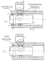
- Vorrichtung zur Bestimmung der Lage zweier durch eine Relativbewegung miteinander verrastbarer und eine elastische Dichtung zwischen sich haltenden Fahrzeugteile, dadurch gekennzeichnet, daß die Dichtung (4) magnetisch ist und daß die Dichtung bei korrekter Lage der beiden Teile (1,2) zueinander einen Verlauf der magnetischen Feldlinien aufweist, der vom Verlauf bei nicht korrekter Lage abweicht.
- Verfahren nach Anspruch 1, dadurch gekennzeichnet, daß die Dichtung (4) aus magnetischem Werkstoff besteht.
- Verfahren unter Verwendung einer Vorrichtung nach Anspruch 1 oder 2, dadurch gekennzeichnet, daß der Verlauf der magnetischen Feldlinien durch einen Magnetfeld-Sensor (7) bestimmt wird, der auf die Solllage der Dichtung (4) bei korrekter Lage der beiden Teile (1,2) zueinander ausgerichtet ist.
Applications Claiming Priority (2)
| Application Number | Priority Date | Filing Date | Title |
|---|---|---|---|
| DE19959664 | 1999-12-10 | ||
| DE1999159664 DE19959664A1 (de) | 1999-12-10 | 1999-12-10 | Verfahren und Vorrichtung zur Bestimmung der relativen Lage zweier Fahrzeugteile |
Publications (3)
| Publication Number | Publication Date |
|---|---|
| EP1106962A2 true EP1106962A2 (de) | 2001-06-13 |
| EP1106962A3 EP1106962A3 (de) | 2003-04-16 |
| EP1106962B1 EP1106962B1 (de) | 2010-03-03 |
Family
ID=7932198
Family Applications (1)
| Application Number | Title | Priority Date | Filing Date |
|---|---|---|---|
| EP00123959A Expired - Lifetime EP1106962B1 (de) | 1999-12-10 | 2000-11-03 | Schnellkupplung |
Country Status (3)
| Country | Link |
|---|---|
| EP (1) | EP1106962B1 (de) |
| DE (2) | DE19959664A1 (de) |
| ES (1) | ES2339214T3 (de) |
Cited By (4)
| Publication number | Priority date | Publication date | Assignee | Title |
|---|---|---|---|---|
| EP1844834A1 (de) * | 2006-04-12 | 2007-10-17 | Millipore Corporation | Filtersitzmonitor |
| US7901627B2 (en) | 2006-04-12 | 2011-03-08 | Millipore Corporation | Filter with memory, communication and concentration sensor |
| US8007568B2 (en) | 2006-04-12 | 2011-08-30 | Millipore Corporation | Filter with memory, communication and pressure sensor |
| WO2018028860A1 (de) * | 2016-08-12 | 2018-02-15 | Voith Patent Gmbh | Überwachen einer relativbewegung zweier elemente |
Citations (2)
| Publication number | Priority date | Publication date | Assignee | Title |
|---|---|---|---|---|
| EP0631057A1 (de) | 1993-06-23 | 1994-12-28 | Firma Carl Freudenberg | Dichtung für einen pneumatisch angetrieben Kolben |
| EP0725242A1 (de) | 1995-02-03 | 1996-08-07 | Firma Carl Freudenberg | Dichtungsanordnung |
Family Cites Families (9)
| Publication number | Priority date | Publication date | Assignee | Title |
|---|---|---|---|---|
| JPS639109A (ja) * | 1986-06-30 | 1988-01-14 | Shin Kobe Electric Mach Co Ltd | リング状樹脂磁石の製造法 |
| JPS63196018A (ja) * | 1987-02-10 | 1988-08-15 | Tdk Corp | インダクタンス素子 |
| IN168269B (de) * | 1987-09-10 | 1991-03-02 | Durametallic Corp | |
| JPH01207908A (ja) * | 1988-02-16 | 1989-08-21 | Sumitomo Electric Ind Ltd | 超電導体導磁パイプ |
| US5078411A (en) * | 1989-01-18 | 1992-01-07 | Norman Geco | Variable magnetic rotary seal |
| GB2270758A (en) * | 1992-09-15 | 1994-03-23 | Platon A & I Limited | Apparatus for determining a parameter of a fluid |
| FR2698421B1 (fr) * | 1992-11-24 | 1995-06-02 | Skf France | Logement pour fixation radiale d'un roulement. |
| JP3073958B2 (ja) * | 1998-04-06 | 2000-08-07 | 株式会社日立製作所 | メカニカルシ−ル用モニタリング装置及び方法 |
| JPH11338246A (ja) * | 1998-05-28 | 1999-12-10 | Canon Inc | 現像装置、プロセスカートリッジ及び画像形成装置 |
-
1999
- 1999-12-10 DE DE1999159664 patent/DE19959664A1/de not_active Withdrawn
-
2000
- 2000-11-03 ES ES00123959T patent/ES2339214T3/es not_active Expired - Lifetime
- 2000-11-03 DE DE50015877T patent/DE50015877D1/de not_active Expired - Lifetime
- 2000-11-03 EP EP00123959A patent/EP1106962B1/de not_active Expired - Lifetime
Patent Citations (2)
| Publication number | Priority date | Publication date | Assignee | Title |
|---|---|---|---|---|
| EP0631057A1 (de) | 1993-06-23 | 1994-12-28 | Firma Carl Freudenberg | Dichtung für einen pneumatisch angetrieben Kolben |
| EP0725242A1 (de) | 1995-02-03 | 1996-08-07 | Firma Carl Freudenberg | Dichtungsanordnung |
Cited By (11)
| Publication number | Priority date | Publication date | Assignee | Title |
|---|---|---|---|---|
| EP1844834A1 (de) * | 2006-04-12 | 2007-10-17 | Millipore Corporation | Filtersitzmonitor |
| EP2016989A1 (de) | 2006-04-12 | 2009-01-21 | Millipore Corporation | Filtersitzmonitor |
| US7901627B2 (en) | 2006-04-12 | 2011-03-08 | Millipore Corporation | Filter with memory, communication and concentration sensor |
| US8007568B2 (en) | 2006-04-12 | 2011-08-30 | Millipore Corporation | Filter with memory, communication and pressure sensor |
| US8084259B2 (en) | 2006-04-12 | 2011-12-27 | Millipore Corporation | Method of insuring the integrity of a filtering element |
| US8137983B2 (en) | 2006-04-12 | 2012-03-20 | Emd Millipore Corporation | Method of maintaining a protein concentration at a tangential flow filter |
| US8147757B2 (en) | 2006-04-12 | 2012-04-03 | Emd Millipore Corporation | Filter with memory, communication and concentration sensor |
| US8221522B2 (en) | 2006-04-12 | 2012-07-17 | Emd Millipore Corporation | Filter with memory, communication and pressure sensor |
| WO2018028860A1 (de) * | 2016-08-12 | 2018-02-15 | Voith Patent Gmbh | Überwachen einer relativbewegung zweier elemente |
| KR20190037301A (ko) * | 2016-08-12 | 2019-04-05 | 보이트 파텐트 게엠베하 | 2개의 요소들의 상대적인 움직임 감시 |
| KR102305846B1 (ko) * | 2016-08-12 | 2021-09-27 | 보이트 파텐트 게엠베하 | 2개의 요소들의 상대적인 움직임 감시 |
Also Published As
| Publication number | Publication date |
|---|---|
| DE50015877D1 (de) | 2010-04-15 |
| DE19959664A1 (de) | 2001-06-13 |
| EP1106962B1 (de) | 2010-03-03 |
| EP1106962A3 (de) | 2003-04-16 |
| ES2339214T3 (es) | 2010-05-18 |
Similar Documents
| Publication | Publication Date | Title |
|---|---|---|
| EP0501234B1 (de) | Verfahren und Vorrichtung zur Messung eines Innendrucks in einem Schlauch | |
| DE19728287B4 (de) | Vorrichtung und Verfahren zur Ausrichtung eines Antriebsstranges | |
| EP4264107B1 (de) | Steckverbinder mit verifizierungselement | |
| EP1106962A2 (de) | Verfahren und Vorrichtung zur Bestimmung der relativen Lage zweier Fahrzeugteile | |
| DE4005545C2 (de) | ||
| DE3319589A1 (de) | Federsystem fuer industrielle manipulatoren | |
| DE4136973A1 (de) | Vorrichtung zur lastverriegelung in flugzeugen | |
| DE69023658T2 (de) | Abdichteinrichtung. | |
| EP1004805A2 (de) | Steckkupplung | |
| DE102008004916A1 (de) | Verfahren zur Kalibrierung der Position eines Magnetfeldsensors | |
| EP3704400B1 (de) | Magnetfeldsensor und verfahren zur montage eines magneten | |
| EP0762036A1 (de) | Lösbare Steckverbindung für Druckluftanlagen in Fahrzeugen | |
| WO1999003023A2 (de) | Verfahren und anordnung zum prüfen eines doppelsensorsystems | |
| DE102016000981A1 (de) | Prüfvorrichtung zum Überprüfen einer Verbindungsanordnung | |
| DE102018123468A1 (de) | Prüfverfahren, Prüfvorrichtung und Anordnung zum Bewerten einer Befestigung einer Leitung an einem Anschlusselement | |
| EP0718536B1 (de) | Leitungsrohrverbindung | |
| DE3116892C2 (de) | Vorrichtung zur berührungslosen Nachführung einer Einrichtung in bezug auf ein Rohr | |
| DE102008057672A1 (de) | Verfahren und Vorrichtung zur Kalibrierung von einem oder mehreren Sensoren eines Fahrzeuges | |
| DE202022101939U1 (de) | Messvorrichtung | |
| DE102015203199B4 (de) | Schaltvorrichtung für ein Kraftfahrzeuggetriebe, Verfahren zur mechanischen Kalibrierung der Schaltvorrichtung und Schaltsystem mit Schaltvorrichtung | |
| DE102017123630B4 (de) | System und Verfahren zum Transport von Transportgütern in einer Montagelinie | |
| DE3540954A1 (de) | Verfahren zum erkennen von auf an messkoerpern angebrachten dehnmessstreifen zurueckzufuehrende messfehler | |
| DE102006041254B4 (de) | Verfahren zur Überprüfung einer elektrischen Lenkung sowie Flurförderzeug mit elektrischer Lenkung | |
| DE10120266B4 (de) | Schlauch mit mindestens einer Markierung, Verfahren zum Montieren einer Hülse auf diesen Schlauch sowie dessen Verwendung | |
| DE102023135120B4 (de) | Anschlusssystem |
Legal Events
| Date | Code | Title | Description |
|---|---|---|---|
| PUAI | Public reference made under article 153(3) epc to a published international application that has entered the european phase |
Free format text: ORIGINAL CODE: 0009012 |
|
| AK | Designated contracting states |
Kind code of ref document: A2 Designated state(s): AT BE CH CY DE DK ES FI FR GB GR IE IT LI LU MC NL PT SE TR |
|
| AX | Request for extension of the european patent |
Free format text: AL;LT;LV;MK;RO;SI |
|
| PUAL | Search report despatched |
Free format text: ORIGINAL CODE: 0009013 |
|
| AK | Designated contracting states |
Designated state(s): AT BE CH CY DE DK ES FI FR GB GR IE IT LI LU MC NL PT SE TR |
|
| AX | Request for extension of the european patent |
Extension state: AL LT LV MK RO SI |
|
| RIC1 | Information provided on ipc code assigned before grant |
Ipc: 7G 01D 5/16 B Ipc: 7G 01D 5/14 B Ipc: 7G 01D 5/20 B Ipc: 7G 01B 7/00 A |
|
| 17P | Request for examination filed |
Effective date: 20030502 |
|
| AKX | Designation fees paid |
Designated state(s): DE ES FR GB IT |
|
| 17Q | First examination report despatched |
Effective date: 20080107 |
|
| GRAP | Despatch of communication of intention to grant a patent |
Free format text: ORIGINAL CODE: EPIDOSNIGR1 |
|
| RTI1 | Title (correction) |
Free format text: QUICK-RELEASE COUPLING |
|
| GRAS | Grant fee paid |
Free format text: ORIGINAL CODE: EPIDOSNIGR3 |
|
| GRAA | (expected) grant |
Free format text: ORIGINAL CODE: 0009210 |
|
| AK | Designated contracting states |
Kind code of ref document: B1 Designated state(s): DE ES FR GB IT |
|
| REG | Reference to a national code |
Ref country code: GB Ref legal event code: FG4D Free format text: NOT ENGLISH |
|
| REF | Corresponds to: |
Ref document number: 50015877 Country of ref document: DE Date of ref document: 20100415 Kind code of ref document: P |
|
| REG | Reference to a national code |
Ref country code: ES Ref legal event code: FG2A Ref document number: 2339214 Country of ref document: ES Kind code of ref document: T3 |
|
| PLBE | No opposition filed within time limit |
Free format text: ORIGINAL CODE: 0009261 |
|
| STAA | Information on the status of an ep patent application or granted ep patent |
Free format text: STATUS: NO OPPOSITION FILED WITHIN TIME LIMIT |
|
| 26N | No opposition filed |
Effective date: 20101206 |
|
| GBPC | Gb: european patent ceased through non-payment of renewal fee |
Effective date: 20101103 |
|
| REG | Reference to a national code |
Ref country code: FR Ref legal event code: ST Effective date: 20110801 |
|
| PG25 | Lapsed in a contracting state [announced via postgrant information from national office to epo] |
Ref country code: FR Free format text: LAPSE BECAUSE OF NON-PAYMENT OF DUE FEES Effective date: 20101130 |
|
| PG25 | Lapsed in a contracting state [announced via postgrant information from national office to epo] |
Ref country code: GB Free format text: LAPSE BECAUSE OF NON-PAYMENT OF DUE FEES Effective date: 20101103 |
|
| PG25 | Lapsed in a contracting state [announced via postgrant information from national office to epo] |
Ref country code: IT Free format text: LAPSE BECAUSE OF NON-PAYMENT OF DUE FEES Effective date: 20101103 |
|
| REG | Reference to a national code |
Ref country code: ES Ref legal event code: FD2A Effective date: 20131029 |
|
| PG25 | Lapsed in a contracting state [announced via postgrant information from national office to epo] |
Ref country code: ES Free format text: LAPSE BECAUSE OF NON-PAYMENT OF DUE FEES Effective date: 20101104 |
|
| PGFP | Annual fee paid to national office [announced via postgrant information from national office to epo] |
Ref country code: DE Payment date: 20151113 Year of fee payment: 16 |
|
| REG | Reference to a national code |
Ref country code: DE Ref legal event code: R119 Ref document number: 50015877 Country of ref document: DE |
|
| PG25 | Lapsed in a contracting state [announced via postgrant information from national office to epo] |
Ref country code: DE Free format text: LAPSE BECAUSE OF NON-PAYMENT OF DUE FEES Effective date: 20170601 |