EP1106943A2 - Refrigerator - Google Patents
Refrigerator Download PDFInfo
- Publication number
- EP1106943A2 EP1106943A2 EP00124284A EP00124284A EP1106943A2 EP 1106943 A2 EP1106943 A2 EP 1106943A2 EP 00124284 A EP00124284 A EP 00124284A EP 00124284 A EP00124284 A EP 00124284A EP 1106943 A2 EP1106943 A2 EP 1106943A2
- Authority
- EP
- European Patent Office
- Prior art keywords
- refrigerant
- run
- refrigerator
- evaporator
- compartment evaporator
- Prior art date
- Legal status (The legal status is an assumption and is not a legal conclusion. Google has not performed a legal analysis and makes no representation as to the accuracy of the status listed.)
- Granted
Links
Images






Classifications
-
- F—MECHANICAL ENGINEERING; LIGHTING; HEATING; WEAPONS; BLASTING
- F25—REFRIGERATION OR COOLING; COMBINED HEATING AND REFRIGERATION SYSTEMS; HEAT PUMP SYSTEMS; MANUFACTURE OR STORAGE OF ICE; LIQUEFACTION SOLIDIFICATION OF GASES
- F25D—REFRIGERATORS; COLD ROOMS; ICE-BOXES; COOLING OR FREEZING APPARATUS NOT OTHERWISE PROVIDED FOR
- F25D11/00—Self-contained movable devices, e.g. domestic refrigerators
-
- F—MECHANICAL ENGINEERING; LIGHTING; HEATING; WEAPONS; BLASTING
- F25—REFRIGERATION OR COOLING; COMBINED HEATING AND REFRIGERATION SYSTEMS; HEAT PUMP SYSTEMS; MANUFACTURE OR STORAGE OF ICE; LIQUEFACTION SOLIDIFICATION OF GASES
- F25D—REFRIGERATORS; COLD ROOMS; ICE-BOXES; COOLING OR FREEZING APPARATUS NOT OTHERWISE PROVIDED FOR
- F25D11/00—Self-contained movable devices, e.g. domestic refrigerators
- F25D11/02—Self-contained movable devices, e.g. domestic refrigerators with cooling compartments at different temperatures
- F25D11/022—Self-contained movable devices, e.g. domestic refrigerators with cooling compartments at different temperatures with two or more evaporators
-
- F—MECHANICAL ENGINEERING; LIGHTING; HEATING; WEAPONS; BLASTING
- F25—REFRIGERATION OR COOLING; COMBINED HEATING AND REFRIGERATION SYSTEMS; HEAT PUMP SYSTEMS; MANUFACTURE OR STORAGE OF ICE; LIQUEFACTION SOLIDIFICATION OF GASES
- F25B—REFRIGERATION MACHINES, PLANTS OR SYSTEMS; COMBINED HEATING AND REFRIGERATION SYSTEMS; HEAT PUMP SYSTEMS
- F25B5/00—Compression machines, plants or systems, with several evaporator circuits, e.g. for varying refrigerating capacity
- F25B5/02—Compression machines, plants or systems, with several evaporator circuits, e.g. for varying refrigerating capacity arranged in parallel
-
- F—MECHANICAL ENGINEERING; LIGHTING; HEATING; WEAPONS; BLASTING
- F25—REFRIGERATION OR COOLING; COMBINED HEATING AND REFRIGERATION SYSTEMS; HEAT PUMP SYSTEMS; MANUFACTURE OR STORAGE OF ICE; LIQUEFACTION SOLIDIFICATION OF GASES
- F25B—REFRIGERATION MACHINES, PLANTS OR SYSTEMS; COMBINED HEATING AND REFRIGERATION SYSTEMS; HEAT PUMP SYSTEMS
- F25B2400/00—Component parts or details not otherwise provided for in this subclass
- F25B2400/19—Pumping down refrigerant from one part of the cycle to another part of the cycle, e.g. when the cycle is changed from cooling to heating, or before a defrost cycle is started
-
- F—MECHANICAL ENGINEERING; LIGHTING; HEATING; WEAPONS; BLASTING
- F25—REFRIGERATION OR COOLING; COMBINED HEATING AND REFRIGERATION SYSTEMS; HEAT PUMP SYSTEMS; MANUFACTURE OR STORAGE OF ICE; LIQUEFACTION SOLIDIFICATION OF GASES
- F25B—REFRIGERATION MACHINES, PLANTS OR SYSTEMS; COMBINED HEATING AND REFRIGERATION SYSTEMS; HEAT PUMP SYSTEMS
- F25B2500/00—Problems to be solved
- F25B2500/12—Sound
-
- F—MECHANICAL ENGINEERING; LIGHTING; HEATING; WEAPONS; BLASTING
- F25—REFRIGERATION OR COOLING; COMBINED HEATING AND REFRIGERATION SYSTEMS; HEAT PUMP SYSTEMS; MANUFACTURE OR STORAGE OF ICE; LIQUEFACTION SOLIDIFICATION OF GASES
- F25B—REFRIGERATION MACHINES, PLANTS OR SYSTEMS; COMBINED HEATING AND REFRIGERATION SYSTEMS; HEAT PUMP SYSTEMS
- F25B2500/00—Problems to be solved
- F25B2500/31—Low ambient temperatures
-
- F—MECHANICAL ENGINEERING; LIGHTING; HEATING; WEAPONS; BLASTING
- F25—REFRIGERATION OR COOLING; COMBINED HEATING AND REFRIGERATION SYSTEMS; HEAT PUMP SYSTEMS; MANUFACTURE OR STORAGE OF ICE; LIQUEFACTION SOLIDIFICATION OF GASES
- F25B—REFRIGERATION MACHINES, PLANTS OR SYSTEMS; COMBINED HEATING AND REFRIGERATION SYSTEMS; HEAT PUMP SYSTEMS
- F25B2600/00—Control issues
- F25B2600/25—Control of valves
- F25B2600/2511—Evaporator distribution valves
-
- F—MECHANICAL ENGINEERING; LIGHTING; HEATING; WEAPONS; BLASTING
- F25—REFRIGERATION OR COOLING; COMBINED HEATING AND REFRIGERATION SYSTEMS; HEAT PUMP SYSTEMS; MANUFACTURE OR STORAGE OF ICE; LIQUEFACTION SOLIDIFICATION OF GASES
- F25D—REFRIGERATORS; COLD ROOMS; ICE-BOXES; COOLING OR FREEZING APPARATUS NOT OTHERWISE PROVIDED FOR
- F25D2400/00—General features of, or devices for refrigerators, cold rooms, ice-boxes, or for cooling or freezing apparatus not covered by any other subclass
- F25D2400/04—Refrigerators with a horizontal mullion
Definitions
- the present invention relates to a refrigerator which is provided with an evaporator for a refrigerator compartment and an evaporator for a freezer compartment.
- a refrigerator is provided with a refrigerator compartment and a freezer compartment, each of which is equipped with a dedicated evaporator in some refrigerators of recent years. These refrigerators have a freezing cycle, as shown in Fig. 13.
- a condenser 103 is connected to the downstream side of a compressor 102, which is divided at its downstream into two branches.
- a refrigerator compartment change-over valve (as will be abbreviated into the "R-valve") 104
- a refrigerator compartment capillary tube as will be abbreviated into the "R-capi”
- a refrigerator compartment evaporator as will be abbreviated into the "R-eva" 108.
- a freezer compartment change-over valve (as will be abbreviated into the "F-valve") 110
- a freezer compartment capillary tube (as will be abbreviated into the "F-capi”)
- a freezer compartment evaporator (as will be abbreviated into the "F-eva”) 114
- a check valve 116 Moreover, the conduits from the check-valve 116 and the R-eva 108 circulate through the compressor 102.
- an R-fan 118 for feeding the air cooled in the R-eva 108 to the refrigerator compartment, and the F-eva 114 is equipped with an F-fan 120.
- a refrigerating run (as will be abbreviated into the "R-mode") for cooling the refrigerator compartment and a freezing run (as will be abbreviated into the "F-mode”) for cooling the freezer compartment are alternately carried out.
- the refrigerator compartment reaches a predetermined temperature, specifically, the R-valve 104 is opened, but the F-valve 110 is opened to feed the refrigerant to the F-eva 114 thereby to establish the F-mode.
- the freezer compartment reaches a predetermined temperature in the F-mode
- the F-valve 110 is closed, but the R-valve 104 is opened to feed the refrigerant to the R-eva 108 thereby to establish the R-mode.
- the R-eva 108 and the F-eva 114 are different in evaporation temperature and in the calorie of evaporation enthalpy. If both the R-eva 108 and the F-eva 114 have a necessary cooling calorie of 40 W, therefore, the refrigerant flow rate in the R-eva 108 is twice as high as that of the F-eva 114 because of the difference in the calorie of the evaporation enthalpy. In other words, when the evaporation temperature rises from a low level to a high level, the necessary refrigerant flow rate is raised by the difference in the specific suction capacity of the compressor 102.
- This difference in the refrigerant circulation rate between the R-eva 108 and the F-eva 114 causes the delay in the refrigerant behaviors at the transition from the F-mode to the R-mode.
- the refrigerant flowing at rate of 1 in the F-mode has to flow at a rate of 2 when the mode is switched to the R-mode.
- the compression ratio of the compressor 102 is high in the F-mode but falls in the R-mode, so that the refrigerant is reluctant to flow into the R-eva 108 due to the difference in the compression ratio.
- the aforementioned delay in the refrigerant behaviors triggers to establish the state, in which anywhere but the entrance portion of the R-eva 108 is not cooled, as shown in Fig. 13. There arises a problem that the exit or its vicinity is not cooled to a necessary temperature so that the sufficient cooling capacity is not exhibited. This problem affects the cooling capacity adversely.
- the refrigerant as has been stagnant in the F-eva 114, cannot flow to the compressor 102 when in the R-mode at the high pressure.
- the refrigerant circulation is so lessened as cannot be adjusted. Therefore, the flow rate of the refrigerant circulation in the freezing cycle 100 changes for each run. Moreover, this change causes a more delay in the refrigerant behaviors.
- the invention contemplates to provide a refrigerator which can control the refrigerant circulation correctly and can reduce the delay in the refrigerant behaviors.
- a refrigerator comprising: a compressor and a condenser connected in the recited order; an evaporator for a refrigerator compartment and an evaporator for a freezer compartment both connected in parallel to the downstream side of the condenser, and switching means interposed between the condenser and the two evaporators for switching the passage for a refrigerant from the condenser, between the refrigerator compartment evaporator and the freezer compartment evaporator; and a condenser fan for cooling the condenser, a cold air circulation fan for the refrigerator compartment for blowing the cold wind of the refrigerator compartment evaporator to the refrigerator compartment, and a cold wind circulation fan for a refrigerator compartment for blowing the cold air of the refrigerator compartment evaporator to the freezer compartment, whereby a refrigerating run for cooling the refrigerator compartment by feeding the refrigerant to the refrigerator compartment evaporator and a freezing run for cooling the freezer compartment by feeding the refrigerant to the freezer compartment evaporator
- the refrigerating run is performed by switching the switching means to feed the refrigerant only to the refrigerator compartment evaporator.
- the refrigerating run is performed by switching the switching means to feed the refrigerant only to the refrigerator compartment evaporator.
- a stop preparatory run for recovering the refrigerant from the freezer compartment evaporator or the refrigerator compartment evaporator to feed the refrigerant to the condenser is performed by running the compressor while switching the switching means to block the refrigerant to be fed to the freezer compartment evaporator or the refrigerator compartment evaporator, and by running the condenser fan at a low speed, and after the stop preparatory run, the compressor and the condenser fan are stopped while the refrigerant to be fed to the freezer compartment evaporator or the refrigerator compartment evaporator being blocked by the switching means.
- the switching means includes two two-way valves.
- the switching means includes a three-way valve.
- a refrigerator comprising: a compressor and a condenser connected in the recited order; an evaporator for a refrigerator compartment and an evaporator for a freezer compartment both connected in parallel to the downstream side of the condenser, and switching means interposed between the condenser and the two evaporators for switching the passage for a refrigerant from the condenser, between the refrigerator compartment evaporator and the freezer compartment evaporator; and a condenser fan for cooling the condenser, a cold air circulation fan for the refrigerator compartment for blowing the cold wind of the refrigerator compartment evaporator to the refrigerator compartment, and a cold wind circulation fan for a refrigerator compartment for blowing the cold air of the refrigerator compartment evaporator to the freezer compartment, whereby a refrigerating run for cooling the refrigerator compartment by feeding the refrigerant to the refrigerator compartment evaporator and a freezing run for cooling the freezer compartment by feeding the refrigerant to the freezer compartment evaporator can
- the refrigerant recovery run is performed either when it is judged that the refrigerant is short in the refrigerator compartment evaporator or the freezer compartment evaporator or at the switching time when the refrigerating run and the freezing run are alternately performed.
- the speed of the compressor at the refrigerant recovery run is continued from that of the compressor, which was set at the refrigerating run or at the freezing run before the transition to the refrigerant recovery run.
- the running time of the refrigerant recovery run is set the longer for the lower speed of the compressor.
- the running time of the refrigerant recovery run is set the longer for the lower ambient temperature.
- the refrigerant recovery run is stopped when the temperature of the refrigerator compartment evaporator or the temperature of the freezer compartment evaporator is lower than a set level.
- an accumulator is further provided on the downstream side of the refrigerant of the refrigerator compartment evaporator, and the refrigerant recovery run is stopped when the temperature of the accumulator becomes lower a set level.
- the cold air circulation fan for the refrigerator compartment or the cold air circulation fan for the freezer compartment is stopped when the temperature of the refrigerator compartment evaporator and the temperature of the freezer compartment evaporator exceeds a set level.
- the compressor is run while blocking the refrigerant to flow to the refrigerator compartment evaporator, and the condenser fan is also run.
- the refrigerant from the freezer compartment evaporator is recovered and fed to the condenser, and this refrigerant is also liquefied by running the condenser fan, thus ending the refrigerant recovery run.
- the switching means is switched to feed the refrigerant only to the refrigerator compartment evaporator thereby to perform the refrigerating run.
- the switching means is switched to feed the refrigerant only to the refrigerator compartment evaporator thereby to perform the refrigerating run.
- the control is made on the basis of the set time, or the refrigerating run is started when the temperature of the freezer compartment evaporator reaches the set level.
- the cold air circulation fan for the refrigerator compartment is run when the temperature of the refrigerator compartment evaporator falls to a set level. In other words, the cold air circulation fan is stopped at the time of starting the refrigerating run. Then, the liquid refrigerating run, as has been stagnant in the condenser, easily flows to the R-eva.
- the stop preparatory run is performed, and the compressor and the condenser fan are then stopped while the refrigerant passages to the individual evaporators being blocked by the switching means.
- the liquefaction of the refrigerant can be promoted by recovering the refrigerant from the freezer compartment evaporator or the refrigerator compartment evaporator to feed it to the condenser and by running the condenser fan at a low speed.
- the refrigerant easily flows to the evaporator at the next return of the compressor, so that the refrigerant delay can be eliminated.
- the time for the stop preparatory run is controlled with the set time or ended when the current value for driving the compressor becomes lower than a set level.
- the switching means can be exemplified by two two-way one or one three-way valve.
- the control is facilitated, and the complicated fluctuation in the compressor speed is suppressed to reduce the noises.
- the refrigerant can be recovered in a substantially proper amount by the simple control.
- the proper amount of refrigerant can be recovered by the simple control even when the ambient temperature changes.
- the excessive refrigerant recovery can be prevented to suppress the deterioration in the reliability of the compressor.
- the cold heat in the evaporator as might otherwise be cooled in an endothermic manner at the refrigerant recovery, can be circulated in the compartment so that the cooling effect of the circulation fan can be made effective to make a contribution to a constant temperature.
- the input increase as might otherwise be caused by excessively driving the circulation fan, can be suppressed to effect a more efficient cooling.
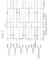
- Fig. 1 is a timing chart illustrating the control state of a refrigerator 1 according to this embodiment
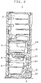
- Fig. 2 is a vertical section of the refrigerator 1
- Fig. 3 is a diagram of a freezing cycle 10 of the refrigerator 1.
- the refrigerator 1 is provided, in the recited downward order, with a refrigerator compartment 2, a crisper 3, an ice compartment 4 and a freezer compartment 5.
- a compressor 12 In a machine compartment 6 on the back of the freezer compartment 5, there is disposed a compressor 12. On the back of the ice compartment 4, on the other hand, there mounted an F-eva 24 and an F-fan 30. On the back of the crisper 3, there are mounted an R-eva 18 and an R-fan 28. In the vicinity of the compressor 6, there is disposed a condenser fan (as will be abbreviated as "C-fan") 32 for cooling the compressor 12 and a condenser 13.
- C-fan condenser fan
- the F-eva 24 cools the ice compartment 4 and the freezer compartment 5
- the R-eva 18 cools the refrigerator compartment 2 and the crisper 3.
- the R-valve 14 In the F-mode for cooling the ice compartment 4 and the freezer compartment 5, the R-valve 14 is closed, but the F-valve 20 is opened. On the other hand, the R-fan 28 is turned OFF, but the F-fan 30 is turned ON. Moreover, the C-fan 32 is rotated at a normal speed.
- the refrigerant flows not into the R-eva 18 but into the F-eva 24 to cool this F-eva 24, and this cooled air is blown to the ice compartment 4 and the freezer compartment 5 by the F-fan 30.
- the evaporation temperature of the F-eva 24 of this case is about at -25°C.
- the compartment temperature of the ice compartment 4 or the freezer compartment 5 falls to a predetermined level whereas the compartment temperature of the refrigerator compartment 2 or the crisper 3 rises to a predetermined level, it is necessary to switch the mode from the F-mode to the R-mode. In this case, the transition is made at the next stage.
- the C-fan 32 runs at a high speed.
- the compressor 12 is continuously run to suck and recover the refrigerant stagnant in the F-eva 24, and this recovered refrigerant is fed to the condenser 13.
- the C-fan 32 is run at the high speed to promote the condensation and the liquidation of the refrigerant so that this liquefied refrigerant is reserved in the condenser 13.
- refrigerant recovery run The run at this first stage will be called the "refrigerant recovery run”. Moreover, this refrigerant recovery run is performed for a set time t1 (e.g., 2 mins.) after the end of the F-mode.
- the R-valve 14 is opened while the F-valve 20 being closed, to feed the liquid refrigerant of the condenser 13 to the R-eva 18.
- the liquid refrigerant as stagnant in the condenser 13, easily flows into the R-eva 18 so that the entrance and exit temperatures of the R-eva 18 can be substantially equalized to eliminate the refrigerant delay.
- the difference of this embodiment from the first embodiment resides in that the ending timing of the refrigerant recovery run from the F-mode to the R-mode is judged in terms of the exit temperature of the F-eva 24.
- This F-eva 24 is run at about -25 °C in the F-mode.
- the C-fan 32 is run at the high speed while the F-valve 20 being closed but the F-fan 30 being run, as described in connection with the first embodiment.
- the refrigerant as stagnant in the F-eva 24, evaporates with the compartment temperature.
- the inside of the F-eva 24 is evacuated by the compressor 12. As a result, the temperature of the F-eva 24 gradually falls, as illustrated in Fig. 4.
- the difference of this embodiment from the first embodiment resides in the following.
- the mode is switched to the R-mode.
- the R-fan 28 is not instantly rotated but is left irrotational at the beginning.
- the R-fan 28 is stopped at first. Moreover, this stopped state of the R-fan 28 is continued till the exit temperature of the R-eva 18 becomes low.
- the R-fan 28 may be stopped only for a set time t2.
- the liquid refrigerant is promptly evaporated and gasified in the R-eva 18.
- the pressure in the piping of the R-eva 18 rises, and the gas has a high pressure loss thereby to cause a phenomenon that the refrigerant becomes stagnant. Therefore, the cooling capacity has to be recovered as soon as possible by feeding the refrigerant to the exit of the R-eva 18 to suppress that gasification thereby to lower the temperature of the R-eva 18 homogeneously.
- this embodiment establishes the control state of the case the compressor 12 is stopped from the F-mode.
- the structures of the refrigerator 1 and the freezing cycle 10 are similar to those of the first embodiment.
- the compressor 12 is stopped after this stop preparatory run is performed for a set time t3 from the end of the F-mode.
- the refrigerant is liable to flow to the evaporator when the next run of the compressor 12 is restored, so that the refrigerant delay can be eliminated.
- the hot gas in the condenser 13 does not flow into the two evaporators so that the evaporator temperature does not rise. In short, the compartment temperature of the refrigerator 1 does not rise so that the restoration is accelerated.
- this stop preparatory run is performed at the end of the F-mode but can also be performed in the R-mode.
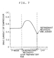
- the difference of this embodiment from the fifth embodiment resides in that the timing for ending the stop preparatory run is judged in terms of not the set time but the current for driving the compressor 12.
- the compressor 12 In the F-mode, more specifically, the compressor 12 is run with a driving current I of about 0.5 A (or 50 W).
- the discharge pressure and the suction pressure are different to load the compressor 12 so that the input of the drive current I rises.
- the load on the compressor 12 is lessened to lower the input value of the drive current I.
- the compressor 12 is stopped.
- the stop preparatory run can be ended at the instant when the refrigerant is reliably recovered.
- the R-valve 14 and the F-valve 20 are made of the different two-way valves but may be replaced by a three-way valve integrating those two valves.
- This three-way valve has one entrance and two exits so that it can realize the following three states.
- the first exit i.e., the exit to the R-eva 18
- the second exit i.e., the exit to the F-eva 24
- the first exit i.e., the exit to the R-eva 18
- the second exit i.e., the exit to the F-eva 24
- the first exit i.e., the exit to the R-eva 18
- the second exit i.e., the exit to the F-eva 24
- Fig. 8 shows the structure of the freezing cycle 10 of this embodiment, which is different from the first embodiment in that a three-way valve 34 is provided in place of the R-valve 14 and the F-valve 20.
- an accumulator 36 is interposed between the F-eva 24 and the check valve 26.
- the three-way valve 34 is of the fully closed type capable of establishing the three states, in which the refrigerant is fed to the R-eva 18, in which the refrigerant is fed to the F-eva 24, and in which the refrigerant is not fed to both the R-eva 18 and the F-eva 24.
- the R-eva 18 has a pressure of about 0.2 MPa and a temperature of about -10 °C.
- the F-eva 24 has a pressure of about 0.1 Mpa and a temperature of about -26 °C.
- the pressures in the evaporators are higher in the R-eva 18 than in the F-eva 24, so that the check valve 26 is closed by the pressure difference to reserve the cold refrigerant in the F-eva 24.
- the cold refrigerant can be used for the cooling operation so that the efficient cooling can be effected in the F-mode without the refrigerant delay.
- the F-eva 24 has a pressure of about 0.1 MPa and a temperature of about -26 °C
- the R-eva 18 has a temperature of 0 to 2 °C but a pressure of 0.1 MPa equal to that of the F-eva 24.
- the pressure of the R-eva 18 is lower than the saturation pressure so that the refrigerant evaporates to establish the dry state (or dry up).
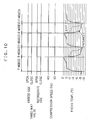
- the three-way valve 34 is switched from that state to make a transition to the R-mode, the refrigerant delay occurs, and the refrigerant takes several minutes to reach the exit side of the R-eva 18.
- Fig. 10 One example of the temperature change and the running state at this time is illustrated in Fig. 10.
- the refrigerant delay occurs in the R-eva 18, which is not effectively exploited in this state. If a back flow is caused for any factor from the check valve 26, on the other hand, the refrigerant becomes short in the R-eva 18.
- the refrigerant resides on the evaporator side at a low temperature.
- the compartment temperatures of the freezer compartment 5 and the refrigerator compartment 2 are near the ambient temperature as just after the power supply, however, much refrigerant may reside in the R-eva 18 in the procedure in which the alternate cooling run is effected by switching the three-way valve 34. Then, it is likely that the refrigerant becomes short even in the F-mode.
- control method of the embodiment is executed, as follows.
- Fig. 11 illustrates the temperatures of the R-eva 18 and the F-eva 24 in the procedure from the power supply to the steady state.
- the refrigerant is stagnant on the evaporator side where the temperature is low, as has been described hereinbefore.
- the evaporator of the lower temperature may be alternately interchanged between the R-eva 18 and the F-eva 24.
- the refrigerant recovery run Before the interchange from the F-mode to the R-mode and before the interchange from the R-mode to the F-mode, therefore, there is performed the refrigerant recovery run.
- the three-way valve 34 is closed to cut the refrigerant from the R-eva 18 and the F-eva 24, and the compressor 12 is run to feed the total refrigerant to the condenser 13, in which the C-fan 32 is rotated to recover the total refrigerant necessary for the condenser 13.
- the cooling is performed by repeating the steps of the R-mode, the refrigerant recovery run, the F-mode, the refrigerant recovery run and the R-mode.
- the necessary refrigerant can be migrated to the condenser 13 so that no refrigerant delay occurs in the individual evaporators after the switching.
- an efficient cooling can be performed while exploiting the performances of the evaporators thereby to shorten the cooling time.
- This embodiment is a modification of the control method of the seventh embodiment.
- the judgment of the refrigerant shortage is made in terms of the entrance temperature and the exit temperature but may also be made when the temperature of the air blown into the compartment rises.
- the refrigerant recovery run is performed as in (1), (3) and (4) before the transition from the F-mode to the R-mode.
- the three-way valve 34 is then fully closed while the runs of the compressor 12 and the C-fan 32 being continued. Then, much refrigerant, as stagnant in the F-eva 24 or the accumulator 36, migrates to the condenser 13 so that it is liquefied.
- This refrigerant recovery run is performed for on minute, for example, the R-mode is established by switching the three-way valve 34 to communicate with the R-eva 18.
- the amount of the refrigerant to be recovered by the refrigerant recovery run depends on the speed of the compressor 12. It is, therefore, desirable to perform the refrigerant recovery run for the running time period proportional to the speed of the compressor 12.
- the F-mode (2) transits during the cooling at the rpm of 50 Hz to the R-mode (2).
- the compressor 12 keeps the rpm of 50 Hz which has been set in the F-mode before the transition.
- the recovery time t3 at this time is exemplified by one minute.
- the cooling is continued at 30 Hz.
- the transition is made like before to the refrigerant recovery run (4) while continuing the rpm of 30 Hz.
- a recovery time t4 at this time is set to a longer value of 3 minutes than the value of 1 minute of the time t3 for the refrigerant recovery at 50 Hz.
- a proper amount of refrigerant can be recovered by setting the refrigerant recovery time for the low speed of the compressor 12 longer than that for the high speed.
- the amount of refrigerant to be recovered depends not only on the speed of the compressor 12, as described above, but also on the ambient temperature at which the refrigerator 1 is placed.
- the running time of the refrigerant recovery run is so set according to the ambient temperature that it is set longer for the lower ambient temperature but shorter for the higher ambient temperature.
- the temperature of the evaporator or accumulator 36 on the refrigerant recovery side is lowered by the evaporation of the refrigerant. If the R-fan 28 or the F-fan 30 corresponding to that evaporator is then rotated, the cool air can be circulated to make a contribution to the constant temperature in the compartment.
- the temperature falls more in the F-eva 24 than in the R-eva 18.
- the freezer compartment 5 can then be cooled even in the refrigerant recovery run.
- the stop of the F-fan 30 at this time is timed, as follows.
- the running time of the F-fan 30 or the R-fan 28 is about one to two minutes, over which there are invited an increase in the fan input and an according rise in the compartment temperature.
- the temperature rise of the F-eva 24 is detected so that the F-fan 30 is stopped if the detected temperature exceeds -20 °C, for example.
- the refrigerant delay can be prevented to control the refrigerant circulation correctly thereby to maximize the cooling ability.
- the balance in the amount of the refrigerant to stagnate in each evaporator can be adjusted, if necessary, to feed a proper amount of refrigerant to each evaporator thereby to perform an efficient cooling.
- the refrigerant recovery is performed so that an efficient cooling can be established while exploiting the performances of the individual evaporators sufficiently.
- the speed of the compressor at the refrigerant recovering time continues that before the transition to the refrigerant recovery run so that the control can be facilitated to prevent the complicated speed fluctuation thereby to reduce the generation of the noises.
- the running time for the refrigerant recovery run is set the longer for the lower speed of the compressor so that the proper amount of refrigerant can be recovered by the simple control.
- the running time for the refrigerant recovery run is set the longer for the lower ambient temperature so that the proper amount of refrigerant can be recovered by the simple control.
- the exit temperature of each evaporator or the temperature of the accumulator is detected so that the refrigerant recovery run is stopped when the detected temperature is lower than the set level. Even during the refrigerant recovery run of an arbitrary time period, therefore, an excessive refrigerant recovery can be prevented to suppress the reliability deterioration of the compressor.
- the cold heat by the refrigerant evaporation can be circulated in the compartment to cool the compartment on the drive side of the circulation fan efficiently and to make a contribution to the constant temperature.
- the cold heat effect by the refrigerant evaporation can be effectively circulated in the compartment thereby to suppress the input increase, as might otherwise be caused by driving the circulation fan excessively.
Landscapes
- Engineering & Computer Science (AREA)
- Physics & Mathematics (AREA)
- Mechanical Engineering (AREA)
- Thermal Sciences (AREA)
- General Engineering & Computer Science (AREA)
- Chemical & Material Sciences (AREA)
- Combustion & Propulsion (AREA)
- Devices That Are Associated With Refrigeration Equipment (AREA)
- Cold Air Circulating Systems And Constructional Details In Refrigerators (AREA)
Abstract
Description
Claims (18)
- A refrigerator comprising:whereby a refrigerating run for cooling the refrigerator compartment by feeding the refrigerant to the refrigerator compartment evaporator and a freezing run for cooling the freezer compartment by feeding the refrigerant to the freezer compartment evaporator can be individually executed by switching the passage of the refrigerant by the switching means, characterized:a compressor and a condenser connected in the recited order;an evaporator for a refrigerator compartment and an evaporator for a freezer compartment both connected in parallel to the downstream side of the condenser, and switching means interposed between the condenser and the two evaporators for switching the passage for a refrigerant from the condenser, between the refrigerator compartment evaporator and the freezer compartment evaporator; anda condenser fan for cooling the condenser, a cold air circulation fan for the refrigerator compartment for blowing the cold wind of the refrigerator compartment evaporator to the refrigerator compartment, and a cold wind circulation fan for a refrigerator compartment for blowing the cold air of the refrigerator compartment evaporator to the freezer compartment,in that at the end of the freezing run, a refrigerant recovery run for recovering the refrigerant from the refrigerator compartment evaporator and feeding it to the condenser is performed by running the compressor while blocking the refrigerant to flow to the freezer compartment evaporator with the switching means and by running the condenser fan; andin that after this refrigerant recovery run, the refrigerating run is performed by switching the switching means to feed the refrigerant only to the refrigerator compartment evaporator.
- A refrigerator according to Claim 1, characterized:
in that after a predetermined time from the start of the refrigerant recovery run, the refrigerating run is performed by switching the switching means to feed the refrigerant only to the refrigerator compartment evaporator. - A refrigerator according to Claim 1, characterized:
in that after the temperature of the freezer compartment evaporator reaches a predetermined level after the start of the refrigerant recovery run, the refrigerating run is performed by switching the switching means to feed the refrigerant only to the refrigerator compartment evaporator. - A refrigerator according to any of Claims 1 to 3, characterized:
in that after the refrigerating run was performed by switching the switching means to feed the refrigerant only to the refrigerator compartment evaporator, the cold air circulation fan for the refrigerator compartment is run when the temperature of the refrigerator compartment evaporator falls to a set level. - A refrigerator according to any of Claims 1 to 4, characterized:in that when the compressor is to be stopped from the freezing run or the refrigerating run, a stop preparatory run for recovering the refrigerant from the freezer compartment evaporator or the refrigerator compartment evaporator to feed the refrigerant to the condenser is performed by running the compressor while switching the switching means to block the refrigerant to be fed to the freezer compartment evaporator or the refrigerator compartment evaporator, and by running the condenser fan at a low speed; andin that after the stop preparatory run, the compressor and the condenser fan are stopped while the refrigerant to be fed to the freezer compartment evaporator or the refrigerator compartment evaporator being blocked by the switching means.
- A refrigerator according to Claim 5, characterized:
in that after a set time from the start of the stop preparatory run, the compressor and the condenser fan are stopped while the refrigerant to be fed to the freezer compartment evaporator or the refrigerator compartment evaporator being blocked by the switching means. - A refrigerator according to Claim 5, characterized:
in that after the drive current value of the compressor became lower than a set level from the start of the stop preparatory run, the compressor and the condenser fan are stopped while the refrigerant to be fed to the freezer compartment evaporator or the refrigerator compartment evaporator being blocked by the switching means. - A refrigerator according to any of Claims 1 to 7, characterized:
in that the switching means includes two two-way valves. - A refrigerator according to any of Claims 1 to 7, characterized:
in that the switching means includes a three-way valve. - A refrigerator comprising:whereby a refrigerating run for cooling the refrigerator compartment by feeding the refrigerant to the refrigerator compartment evaporator and a freezing run for cooling the freezer compartment by feeding the refrigerant to the freezer compartment evaporator can be individually executed by switching the passage of the refrigerant by the switching means, characterized:a compressor and a condenser connected in the recited order;an evaporator for a refrigerator compartment and an evaporator for a freezer compartment both connected in parallel to the downstream side of the condenser, and switching means interposed between the condenser and the two evaporators for switching the passage for a refrigerant from the condenser, between the refrigerator compartment evaporator and the freezer compartment evaporator; anda condenser fan for cooling the condenser, a cold air circulation fan for the refrigerator compartment for blowing the cold wind of the refrigerator compartment evaporator to the refrigerator compartment, and a cold wind circulation fan for a refrigerator compartment for blowing the cold air of the refrigerator compartment evaporator to the freezer compartment,by further comprising block means for blocking the refrigerant to flow to the refrigerator compartment evaporator and the freezer compartment evaporator; andin that a refrigerant recovery run for recovering the refrigerant to feed it to the condenser is performed by running the compressor while the refrigerant to flow to the refrigerator compartment evaporator and the freezer compartment evaporator being blocked by the block means, and by running the condenser fan.
- A refrigerator according to Claim 10, characterized:
in that the refrigerant recovery run is performed either when it is judged that the refrigerant is short in the refrigerator compartment evaporator or the freezer compartment evaporator or at the switching time when the refrigerating run and the freezing run are alternately performed. - A refrigerator according to Claim 10, characterized:
in that the speed of the compressor at the refrigerant recovery run is continued from that of the compressor, which was set at the refrigerating run or at the freezing run before the transition to the refrigerant recovery run. - A refrigerator according to Claim 10, characterized:
in that the running time of the refrigerant recovery run is set the longer for the lower speed of the compressor. - A refrigerator according to Claim 10, characterized:
in that the running time of the refrigerant recovery run is set the longer for the lower ambient temperature. - A refrigerator according to Claim 10, characterized:
in that the refrigerant recovery run is stopped when the temperature of the refrigerator compartment evaporator or the temperature of the freezer compartment evaporator is lower than a set level. - A refrigerator according to Claim 10, characterized:by further comprising an accumulator on the downstream side of the refrigerant of the refrigerator compartment evaporator; andin that the refrigerant recovery run is stopped when the temperature of the accumulator becomes lower a set level.
- A refrigerator according to Claim 10, characterized:
in that either the cold air circulation fan for the refrigerator compartment at the refrigerating run before the transition to the refrigerant recovery run or the cold air circulation fan for the freezer compartment at the freezing run is continuously rotated. - A refrigerator according to Claim 17, characterized:
in that the cold air circulation fan for the refrigerator compartment or the cold air circulation fan for the freezer compartment is stopped when the temperature of the refrigerator compartment evaporator and the temperature of the freezer compartment evaporator exceeds a set level.
Applications Claiming Priority (4)
| Application Number | Priority Date | Filing Date | Title |
|---|---|---|---|
| JP33982399 | 1999-11-30 | ||
| JP33982399 | 1999-11-30 | ||
| JP2000212744A JP3462156B2 (en) | 1999-11-30 | 2000-07-13 | refrigerator |
| JP2000212744 | 2000-07-13 |
Publications (3)
| Publication Number | Publication Date |
|---|---|
| EP1106943A2 true EP1106943A2 (en) | 2001-06-13 |
| EP1106943A3 EP1106943A3 (en) | 2001-08-22 |
| EP1106943B1 EP1106943B1 (en) | 2005-08-10 |
Family
ID=26576543
Family Applications (1)
| Application Number | Title | Priority Date | Filing Date |
|---|---|---|---|
| EP00124284A Expired - Lifetime EP1106943B1 (en) | 1999-11-30 | 2000-11-14 | Refrigerator |
Country Status (7)
| Country | Link |
|---|---|
| US (1) | US6397608B1 (en) |
| EP (1) | EP1106943B1 (en) |
| JP (1) | JP3462156B2 (en) |
| KR (1) | KR100352536B1 (en) |
| CN (1) | CN100402959C (en) |
| DE (1) | DE60021840T2 (en) |
| TW (1) | TW504560B (en) |
Cited By (13)
| Publication number | Priority date | Publication date | Assignee | Title |
|---|---|---|---|---|
| EP1376031A2 (en) | 2002-06-26 | 2004-01-02 | Lg Electronics Inc. | Method for controlling operation of cooling system having two evaporators |
| WO2007115879A1 (en) * | 2006-04-05 | 2007-10-18 | BSH Bosch und Siemens Hausgeräte GmbH | Method for operating a refrigerating device comprising evaporators which are connected in parallel and refrigerating device therefor |
| WO2008082084A1 (en) | 2007-01-03 | 2008-07-10 | Lg Electronics, Inc. | Separate-cooling type refrigerator |
| CN100458317C (en) * | 2004-09-07 | 2009-02-04 | 乐金电子(天津)电器有限公司 | Refrigerating circulator of straight-cooled refrigerator |
| FR2924488A1 (en) * | 2007-11-29 | 2009-06-05 | Eurocave Sa Sa | POSITIVE COLD COOLING UNIT AND DEVICES USING SUCH A UNIT |
| US20100095691A1 (en) * | 2007-03-12 | 2010-04-22 | Naoshi Kondou | Cooling storage and method of operating the same |
| EP2339274A3 (en) * | 2009-12-22 | 2014-01-08 | Samsung Electronics Co., Ltd. | Refrigerator and method of controlling operation thereof |
| DE10260350B4 (en) * | 2002-07-04 | 2015-11-26 | Lg Electronics Inc. | A method of controlling operation of a dual evaporator cooling system |
| EP3112775A1 (en) * | 2015-07-02 | 2017-01-04 | Samsung Electronics Co., Ltd. | Refrigerator and method for controlling the same |
| CN107421152A (en) * | 2017-08-17 | 2017-12-01 | 珠海格力电器股份有限公司 | Cooling system and control method thereof |
| WO2019233814A1 (en) * | 2018-06-05 | 2019-12-12 | Arcelik Anonim Sirketi | A cooling system |
| WO2022039362A1 (en) | 2020-08-19 | 2022-02-24 | Lg Electronics Inc. | Refrigerator and control method thereof |
| US20240210078A1 (en) * | 2021-04-26 | 2024-06-27 | Electrolux Appliances Aktiebolag | Control of cooling system with multiple cooling lines |
Families Citing this family (52)
| Publication number | Priority date | Publication date | Assignee | Title |
|---|---|---|---|---|
| JP4085694B2 (en) * | 2002-02-27 | 2008-05-14 | 株式会社デンソー | Air conditioner |
| KR100474910B1 (en) * | 2002-07-04 | 2005-03-08 | 엘지전자 주식회사 | method for controling cooling system with two evaporators |
| US6952930B1 (en) | 2003-03-31 | 2005-10-11 | General Electric Company | Methods and apparatus for controlling refrigerators |
| US20050210898A1 (en) * | 2004-03-23 | 2005-09-29 | Samsung Electronics Co., Ltd. | Refrigerator and control method thereof |
| JP2006275496A (en) | 2005-03-30 | 2006-10-12 | Sanyo Electric Co Ltd | Refrigerating device and refrigerator |
| KR100687934B1 (en) * | 2005-09-28 | 2007-02-27 | 삼성전자주식회사 | Refrigerator and its control method |
| JP4528755B2 (en) * | 2006-07-14 | 2010-08-18 | 株式会社東芝 | refrigerator |
| KR100826179B1 (en) | 2006-11-14 | 2008-04-30 | 엘지전자 주식회사 | Refrigerator and its control method |
| KR100806313B1 (en) * | 2007-03-30 | 2008-03-03 | 엘지전자 주식회사 | Refrigerator Control Method |
| KR100870540B1 (en) | 2007-03-30 | 2008-11-26 | 엘지전자 주식회사 | Refrigerator Control Method |
| KR100806314B1 (en) * | 2007-03-30 | 2008-02-27 | 엘지전자 주식회사 | Refrigerator Control Method |
| KR101275184B1 (en) | 2007-05-25 | 2013-06-18 | 엘지전자 주식회사 | Control method of refrigerating system |
| KR101314622B1 (en) * | 2007-11-05 | 2013-10-07 | 엘지전자 주식회사 | Controlling method for the refrigerator |
| KR101314621B1 (en) * | 2007-11-05 | 2013-10-07 | 엘지전자 주식회사 | Controlling method for the refrigerator |
| JP2010025483A (en) * | 2008-07-22 | 2010-02-04 | Fukushima Industries Corp | Cooling storage |
| JP2010025484A (en) * | 2008-07-22 | 2010-02-04 | Fukushima Industries Corp | Cooling storage |
| JP5366292B2 (en) * | 2008-07-22 | 2013-12-11 | 福島工業株式会社 | Freezer refrigerator |
| JP5079647B2 (en) * | 2008-09-22 | 2012-11-21 | 福島工業株式会社 | Refrigerator |
| US20100326096A1 (en) * | 2008-11-10 | 2010-12-30 | Brent Alden Junge | Control sytem for bottom freezer refrigerator with ice maker in upper door |
| CN101447142B (en) * | 2008-12-11 | 2012-06-27 | 杨洪林 | Refrigeration experiment (practical training) device |
| US20120043345A1 (en) * | 2009-03-18 | 2012-02-23 | U.S.A. Vendicab Corp. | Passenger vehicle-for-hire vending machine with refrigeration |
| JP5624289B2 (en) * | 2009-07-01 | 2014-11-12 | 株式会社東芝 | refrigerator |
| CN102575885B (en) * | 2009-10-07 | 2014-09-10 | 三菱电机株式会社 | Refrigeration cycle device |
| KR101658552B1 (en) * | 2010-01-22 | 2016-09-21 | 엘지전자 주식회사 | A refrigerator and a control method thereof |
| US20130186129A1 (en) * | 2012-01-25 | 2013-07-25 | Lg Electronics Inc. | Refrigerator |
| KR101918224B1 (en) * | 2012-01-31 | 2018-11-13 | 엘지전자 주식회사 | Refrigerator and Control method of the same |
| US9140477B2 (en) | 2012-05-21 | 2015-09-22 | Whirlpool Corporation | Synchronous compartment temperature control and apparatus for refrigeration with reduced energy consumption |
| US9140479B2 (en) | 2012-05-21 | 2015-09-22 | Whirlpool Corporation | Synchronous temperature rate control and apparatus for refrigeration with reduced energy consumption |
| US9140478B2 (en) | 2012-05-21 | 2015-09-22 | Whirlpool Corporation | Synchronous temperature rate control for refrigeration with reduced energy consumption |
| KR20140115838A (en) * | 2013-03-22 | 2014-10-01 | 엘지전자 주식회사 | Method for controlling refrigerator |
| US9982927B2 (en) * | 2013-11-04 | 2018-05-29 | Lg Electronics Inc. | Refrigerator and method of controlling the same |
| KR101761996B1 (en) * | 2015-04-21 | 2017-07-26 | 엘지전자 주식회사 | A refrigerator and a control method the same |
| KR101770467B1 (en) * | 2015-06-30 | 2017-08-22 | 엘지전자 주식회사 | Refrigerator and colntrol method for refrigerator |
| CN105042985B (en) * | 2015-07-10 | 2017-09-22 | 合肥美菱股份有限公司 | A kind of distribution method of double systems connected in parallel refrigerator flow |
| CN105258449B (en) * | 2015-11-05 | 2018-04-20 | 青岛海尔股份有限公司 | Using the refrigerator and its control method of linear compressor |
| KR102367222B1 (en) * | 2017-03-22 | 2022-02-25 | 엘지전자 주식회사 | Refrigerator and method for controlling the same |
| CN108885054B (en) | 2016-03-24 | 2020-11-13 | Lg 电子株式会社 | Refrigerator and control method thereof |
| CN105972915A (en) * | 2016-05-25 | 2016-09-28 | 合肥华凌股份有限公司 | Control method and control device for refrigeration system, and refrigerator |
| CN106091457B (en) * | 2016-05-25 | 2019-05-17 | 合肥华凌股份有限公司 | Refrigeration system, its control method and control device, refrigerator |
| TR201612401A2 (en) * | 2016-09-01 | 2018-03-21 | Arcelik As | A cooling device with an ice-making compartment and its control method |
| KR102151817B1 (en) * | 2016-11-30 | 2020-09-04 | 엘지전자 주식회사 | Refrigerator and method for controlling the same |
| KR102177946B1 (en) * | 2016-12-02 | 2020-11-12 | 엘지전자 주식회사 | Refrigerator |
| CN106482435A (en) * | 2016-12-05 | 2017-03-08 | 天津商业大学 | A kind of natural Defrost method of cold storage refrigerating system |
| KR102198955B1 (en) * | 2016-12-07 | 2021-01-06 | 엘지전자 주식회사 | Refrigerator and method for controlling the same |
| WO2018134949A1 (en) * | 2017-01-19 | 2018-07-26 | 三菱電機株式会社 | Refrigeration cycle device |
| JP7005172B2 (en) * | 2017-05-26 | 2022-01-21 | 日立ジョンソンコントロールズ空調株式会社 | Air conditioner |
| KR102401782B1 (en) * | 2017-11-02 | 2022-05-26 | 엘지전자 주식회사 | Refrigerator and method for controlling the same |
| DE102019201291A1 (en) | 2019-02-01 | 2020-08-06 | BSH Hausgeräte GmbH | Refrigerator with parallel evaporators and operating procedures therefor |
| KR102674401B1 (en) * | 2019-02-28 | 2024-06-13 | 엘지전자 주식회사 | Control method for refrigerator |
| CN114992969A (en) * | 2022-04-25 | 2022-09-02 | 珠海格力电器股份有限公司 | Time-sharing power utilization control method and device and refrigerator |
| CN116358199B (en) * | 2023-03-30 | 2025-07-04 | 广东西屋康达空调有限公司 | A refrigerant recovery method for a refrigeration system, a refrigeration system and a storage medium |
| WO2026054273A1 (en) * | 2024-09-04 | 2026-03-12 | 삼성전자주식회사 | Refrigerator and method for controlling same |
Family Cites Families (15)
| Publication number | Priority date | Publication date | Assignee | Title |
|---|---|---|---|---|
| JPS5888559A (en) * | 1981-11-20 | 1983-05-26 | 三菱電機株式会社 | Cooling device |
| US5077982A (en) * | 1990-02-14 | 1992-01-07 | York International Corporation | Multizone air conditioning system and evaporators therefor |
| JP2850491B2 (en) * | 1990-06-07 | 1999-01-27 | 富士電機株式会社 | Operation control method of refrigerator |
| CN1057330A (en) * | 1990-06-13 | 1991-12-25 | 陈杰然 | Conditioning device for refrigerator |
| CN2115501U (en) * | 1990-12-12 | 1992-09-09 | 陈杰然 | Refrigerator air-conditioner |
| CN2090500U (en) * | 1991-01-31 | 1991-12-11 | 上海新中华机器厂 | Indirect-and direct-cooling mixed dual-door dual-temp. refrigerator |
| US5465591A (en) * | 1992-08-14 | 1995-11-14 | Whirlpool Corporation | Dual evaporator refrigerator with non-simultaneous evaporator |
| DE4429919A1 (en) * | 1994-08-23 | 1996-02-29 | Bosch Siemens Hausgeraete | Circuit arrangement for operating an electrically controllable solenoid valve |
| JP3523381B2 (en) * | 1995-07-26 | 2004-04-26 | 株式会社日立製作所 | refrigerator |
| JPH09300949A (en) * | 1996-05-17 | 1997-11-25 | Mitsubishi Heavy Ind Ltd | Vehicular air conditioner with accumulator cooling device |
| JPH1053019A (en) * | 1996-06-03 | 1998-02-24 | Denso Corp | Vehicle air conditioner |
| JP3049425B2 (en) * | 1997-06-30 | 2000-06-05 | エルジー電子株式会社 | Refrigerator with two evaporators |
| KR20000055341A (en) * | 1999-02-05 | 2000-09-05 | 윤종용 | Control method for intercooler refrigerator |
| JP4178646B2 (en) * | 1999-02-09 | 2008-11-12 | 松下電器産業株式会社 | refrigerator |
| JP3430159B2 (en) | 2001-05-11 | 2003-07-28 | 松下冷機株式会社 | refrigerator |
-
2000
- 2000-07-13 JP JP2000212744A patent/JP3462156B2/en not_active Expired - Lifetime
- 2000-09-22 TW TW089119668A patent/TW504560B/en not_active IP Right Cessation
- 2000-10-19 KR KR1020000061494A patent/KR100352536B1/en not_active Expired - Fee Related
- 2000-11-14 EP EP00124284A patent/EP1106943B1/en not_active Expired - Lifetime
- 2000-11-14 DE DE60021840T patent/DE60021840T2/en not_active Expired - Fee Related
- 2000-11-28 US US09/722,383 patent/US6397608B1/en not_active Expired - Fee Related
- 2000-11-30 CN CNB001350846A patent/CN100402959C/en not_active Expired - Lifetime
Cited By (22)
| Publication number | Priority date | Publication date | Assignee | Title |
|---|---|---|---|---|
| EP1376031A3 (en) * | 2002-06-26 | 2009-04-08 | Lg Electronics Inc. | Method for controlling operation of cooling system having two evaporators |
| EP1376031A2 (en) | 2002-06-26 | 2004-01-02 | Lg Electronics Inc. | Method for controlling operation of cooling system having two evaporators |
| DE10260350B4 (en) * | 2002-07-04 | 2015-11-26 | Lg Electronics Inc. | A method of controlling operation of a dual evaporator cooling system |
| CN100458317C (en) * | 2004-09-07 | 2009-02-04 | 乐金电子(天津)电器有限公司 | Refrigerating circulator of straight-cooled refrigerator |
| CN101416005B (en) * | 2006-04-05 | 2011-05-11 | Bsh博世和西门子家用器具有限公司 | Method for operating a refrigerating device comprising evaporators which are connected in parallel and refrigerating device therefor |
| WO2007115879A1 (en) * | 2006-04-05 | 2007-10-18 | BSH Bosch und Siemens Hausgeräte GmbH | Method for operating a refrigerating device comprising evaporators which are connected in parallel and refrigerating device therefor |
| WO2008082084A1 (en) | 2007-01-03 | 2008-07-10 | Lg Electronics, Inc. | Separate-cooling type refrigerator |
| EP2097691A4 (en) * | 2007-01-03 | 2010-04-07 | Lg Electronics Inc | SEPARATE COOLING TYPE REFRIGERATOR |
| US20100095691A1 (en) * | 2007-03-12 | 2010-04-22 | Naoshi Kondou | Cooling storage and method of operating the same |
| EP2124000A4 (en) * | 2007-03-12 | 2011-03-09 | Hoshizaki Electric Co Ltd | Cooling storage building and method of operating the same |
| FR2924488A1 (en) * | 2007-11-29 | 2009-06-05 | Eurocave Sa Sa | POSITIVE COLD COOLING UNIT AND DEVICES USING SUCH A UNIT |
| WO2009071849A3 (en) * | 2007-11-29 | 2009-11-12 | Eurocave Sa | Positive cold cooling unit and devices using such unit |
| EP2339274A3 (en) * | 2009-12-22 | 2014-01-08 | Samsung Electronics Co., Ltd. | Refrigerator and method of controlling operation thereof |
| EP3112775A1 (en) * | 2015-07-02 | 2017-01-04 | Samsung Electronics Co., Ltd. | Refrigerator and method for controlling the same |
| US10139149B2 (en) | 2015-07-02 | 2018-11-27 | Samsung Electronics Co., Ltd. | Refrigerator and method for controlling the same |
| CN107421152A (en) * | 2017-08-17 | 2017-12-01 | 珠海格力电器股份有限公司 | Cooling system and control method thereof |
| WO2019233814A1 (en) * | 2018-06-05 | 2019-12-12 | Arcelik Anonim Sirketi | A cooling system |
| WO2022039362A1 (en) | 2020-08-19 | 2022-02-24 | Lg Electronics Inc. | Refrigerator and control method thereof |
| EP4200572A4 (en) * | 2020-08-19 | 2024-03-27 | LG Electronics Inc. | REFRIGERATOR AND ASSOCIATED CONTROL METHOD |
| US12222145B2 (en) | 2020-08-19 | 2025-02-11 | Lg Electronics Inc. | Refrigerator with refrigerant recovery control |
| US20240210078A1 (en) * | 2021-04-26 | 2024-06-27 | Electrolux Appliances Aktiebolag | Control of cooling system with multiple cooling lines |
| US12540761B2 (en) * | 2021-04-26 | 2026-02-03 | Electrolux Appliances Aktiebolag | Control of cooling system with multiple cooling lines |
Also Published As
| Publication number | Publication date |
|---|---|
| TW504560B (en) | 2002-10-01 |
| US6397608B1 (en) | 2002-06-04 |
| JP2001221556A (en) | 2001-08-17 |
| DE60021840D1 (en) | 2005-09-15 |
| CN100402959C (en) | 2008-07-16 |
| KR20010051119A (en) | 2001-06-25 |
| KR100352536B1 (en) | 2002-09-12 |
| HK1037024A1 (en) | 2002-01-25 |
| EP1106943B1 (en) | 2005-08-10 |
| DE60021840T2 (en) | 2006-06-01 |
| EP1106943A3 (en) | 2001-08-22 |
| JP3462156B2 (en) | 2003-11-05 |
| CN1298083A (en) | 2001-06-06 |
Similar Documents
| Publication | Publication Date | Title |
|---|---|---|
| EP1106943B1 (en) | Refrigerator | |
| US6598410B2 (en) | Refrigerator with a plurality of parallel refrigerant passages | |
| KR960010634B1 (en) | Heat storage type air-conditioning apparatus | |
| EP1182410B1 (en) | Refrigerator and method of controlling the same | |
| KR102370565B1 (en) | A refrigerator | |
| CN104613699A (en) | Refrigerator | |
| JP5624289B2 (en) | refrigerator | |
| JP2010133586A (en) | Refrigerating cycle device and method of controlling the refrigerating cycle device | |
| JP4178646B2 (en) | refrigerator | |
| JP2003028553A (en) | refrigerator | |
| EP1376031B1 (en) | Method for controlling operation of cooling system having two evaporators | |
| JP3576040B2 (en) | Cooling systems and refrigerators | |
| JP3847499B2 (en) | Two-stage compression refrigeration system | |
| KR100691587B1 (en) | Refrigerator | |
| JP4021209B2 (en) | refrigerator | |
| JPH09210515A (en) | Refrigeration equipment | |
| KR100293700B1 (en) | Refrigeration system of refrigerator and its control method | |
| HK1037024B (en) | Refrigerator | |
| KR20120003224A (en) | Refrigerant circulation system of refrigeration unit | |
| JP2018173195A (en) | Refrigerator | |
| JP2002031459A (en) | refrigerator | |
| JP2002267312A (en) | Freezer refrigerator | |
| JP2006162240A (en) | Refrigeration equipment | |
| JP2008138979A (en) | Refrigeration system | |
| KR100785118B1 (en) | Refrigerator |
Legal Events
| Date | Code | Title | Description |
|---|---|---|---|
| PUAI | Public reference made under article 153(3) epc to a published international application that has entered the european phase |
Free format text: ORIGINAL CODE: 0009012 |
|
| AK | Designated contracting states |
Kind code of ref document: A2 Designated state(s): AT BE CH CY DE DK ES FI FR GB GR IE IT LI LU MC NL PT SE TR |
|
| AX | Request for extension of the european patent |
Free format text: AL;LT;LV;MK;RO;SI |
|
| PUAL | Search report despatched |
Free format text: ORIGINAL CODE: 0009013 |
|
| AK | Designated contracting states |
Kind code of ref document: A3 Designated state(s): AT BE CH CY DE DK ES FI FR GB GR IE IT LI LU MC NL PT SE TR |
|
| AX | Request for extension of the european patent |
Free format text: AL;LT;LV;MK;RO;SI |
|
| 17P | Request for examination filed |
Effective date: 20011130 |
|
| AKX | Designation fees paid |
Free format text: DE FR GB IT |
|
| 17Q | First examination report despatched |
Effective date: 20030129 |
|
| GRAP | Despatch of communication of intention to grant a patent |
Free format text: ORIGINAL CODE: EPIDOSNIGR1 |
|
| RIN1 | Information on inventor provided before grant (corrected) |
Inventor name: NOGUCHI, AKIHIRO Inventor name: DOI, TAKASHI Inventor name: TAGO, MASATO Inventor name: SAKUMA, TSUTOMU Inventor name: KASHIMA, KOJI |
|
| GRAS | Grant fee paid |
Free format text: ORIGINAL CODE: EPIDOSNIGR3 |
|
| GRAA | (expected) grant |
Free format text: ORIGINAL CODE: 0009210 |
|
| AK | Designated contracting states |
Kind code of ref document: B1 Designated state(s): DE FR GB IT |
|
| REG | Reference to a national code |
Ref country code: GB Ref legal event code: FG4D |
|
| REF | Corresponds to: |
Ref document number: 60021840 Country of ref document: DE Date of ref document: 20050915 Kind code of ref document: P |
|
| PGFP | Annual fee paid to national office [announced via postgrant information from national office to epo] |
Ref country code: GB Payment date: 20051109 Year of fee payment: 6 |
|
| PGFP | Annual fee paid to national office [announced via postgrant information from national office to epo] |
Ref country code: DE Payment date: 20051121 Year of fee payment: 6 |
|
| REG | Reference to a national code |
Ref country code: HK Ref legal event code: GR Ref document number: 1037024 Country of ref document: HK |
|
| PLBE | No opposition filed within time limit |
Free format text: ORIGINAL CODE: 0009261 |
|
| STAA | Information on the status of an ep patent application or granted ep patent |
Free format text: STATUS: NO OPPOSITION FILED WITHIN TIME LIMIT |
|
| 26N | No opposition filed |
Effective date: 20060511 |
|
| PG25 | Lapsed in a contracting state [announced via postgrant information from national office to epo] |
Ref country code: FR Free format text: LAPSE BECAUSE OF FAILURE TO SUBMIT A TRANSLATION OF THE DESCRIPTION OR TO PAY THE FEE WITHIN THE PRESCRIBED TIME-LIMIT Effective date: 20060811 |
|
| EN | Fr: translation not filed | ||
| PGFP | Annual fee paid to national office [announced via postgrant information from national office to epo] |
Ref country code: IT Payment date: 20061130 Year of fee payment: 7 |
|
| PG25 | Lapsed in a contracting state [announced via postgrant information from national office to epo] |
Ref country code: DE Free format text: LAPSE BECAUSE OF NON-PAYMENT OF DUE FEES Effective date: 20070601 |
|
| GBPC | Gb: european patent ceased through non-payment of renewal fee |
Effective date: 20061114 |
|
| PG25 | Lapsed in a contracting state [announced via postgrant information from national office to epo] |
Ref country code: GB Free format text: LAPSE BECAUSE OF NON-PAYMENT OF DUE FEES Effective date: 20061114 |
|
| PG25 | Lapsed in a contracting state [announced via postgrant information from national office to epo] |
Ref country code: FR Free format text: LAPSE BECAUSE OF FAILURE TO SUBMIT A TRANSLATION OF THE DESCRIPTION OR TO PAY THE FEE WITHIN THE PRESCRIBED TIME-LIMIT Effective date: 20050810 |
|
| PG25 | Lapsed in a contracting state [announced via postgrant information from national office to epo] |
Ref country code: IT Free format text: LAPSE BECAUSE OF NON-PAYMENT OF DUE FEES Effective date: 20071114 |