JP3576040B2 - Cooling systems and refrigerators - Google Patents
Cooling systems and refrigerators Download PDFInfo
- Publication number
- JP3576040B2 JP3576040B2 JP16329699A JP16329699A JP3576040B2 JP 3576040 B2 JP3576040 B2 JP 3576040B2 JP 16329699 A JP16329699 A JP 16329699A JP 16329699 A JP16329699 A JP 16329699A JP 3576040 B2 JP3576040 B2 JP 3576040B2
- Authority
- JP
- Japan
- Prior art keywords
- flow path
- refrigerant
- control means
- evaporator
- path control
- Prior art date
- Legal status (The legal status is an assumption and is not a legal conclusion. Google has not performed a legal analysis and makes no representation as to the accuracy of the status listed.)
- Expired - Lifetime
Links
Images


Classifications
-
- F—MECHANICAL ENGINEERING; LIGHTING; HEATING; WEAPONS; BLASTING
- F25—REFRIGERATION OR COOLING; COMBINED HEATING AND REFRIGERATION SYSTEMS; HEAT PUMP SYSTEMS; MANUFACTURE OR STORAGE OF ICE; LIQUEFACTION SOLIDIFICATION OF GASES
- F25B—REFRIGERATION MACHINES, PLANTS OR SYSTEMS; COMBINED HEATING AND REFRIGERATION SYSTEMS; HEAT PUMP SYSTEMS
- F25B2600/00—Control issues
- F25B2600/25—Control of valves
- F25B2600/2511—Evaporator distribution valves
Description
【0001】
【発明の属する技術分野】
本発明は、冷蔵庫などにもちいる冷却システムに関するものである。
【0002】
【従来の技術】
図12に従来の冷却サイクル並びに冷蔵庫の一例として、特公昭62−22396号公報に開示されている冷蔵庫の概略図を示す。
【0003】
1は一定速圧縮機、2は凝縮器、3は冷蔵室4内に配設された第一の蒸発器であり、5は冷凍室6内に配設された第二の蒸発器である。
【0004】
7は冷蔵室冷却用である第一の蒸発器3の冷媒回路上流側に配設された第一の減圧手段(キャピラリ)であり、8は冷凍室冷却用である第二の蒸発器5の冷媒回路上流側に配設された第二の減圧手段(キャピラリ)であり、9は冷凍室冷却用の第二の蒸発器5の下流側に設けた逆止弁である。
【0005】
10は第一の蒸発器3の冷媒回路下流側に配設された第一の開閉弁であり、11は第二のキャピラリ8の冷媒回路上流側に設けられた第二の開閉弁である。
【0006】
以上のように構成された従来例の冷蔵庫について、以下その動作を説明する。
【0007】
冷凍サイクルの運転は以下のように行われる。まず圧縮機1により圧縮された冷媒が凝縮器2で凝縮液化される。凝縮された冷媒は第一のキャピラリ7もしくは第二のキャピラリ8で減圧されて、それぞれ第一の蒸発器3、第二の蒸発器5へ流入、蒸発気化された後、再び圧縮機1へと吸入される。
【0008】
冷媒が蒸発気化することにより比較的低温となった第一の蒸発器3、第二の蒸発器5と冷蔵室4、冷凍室6の空気が熱交換することにより各室が冷却される。
【0009】
冷蔵庫の冷却運転は図示しない各室の温度検知手段と制御手段により以下のように行われる。
【0010】
冷蔵室4、冷凍室6の各温度検知手段が所定値以上の温度上昇を検知すると圧縮機1が起動し、冷凍サイクルの運転が行われる。冷蔵室4の温度検知手段が所定値以下となるまで第一の開閉弁10が開放となり、第二の開閉弁11は閉止となる。
【0011】
これにより冷媒は第二の蒸発器5には流入することなく、第一の蒸発器3へのみ流れる。このときの冷凍サイクルの蒸発温度の設定は、冷蔵室4の温度設定が5℃程度に対して−5〜0℃であり、通常の−30〜−25℃の蒸発温度に対して2〜2.5倍の成績係数で圧縮機の運転が可能である。
【0012】
冷蔵室4が冷却されて温度が低下し、温度検知手段が所定値以下を検知すると、第一の開閉弁10が閉止し、第二の開閉弁11が開放となる。
【0013】
これにより冷媒は第二の蒸発器5へと流入し、冷凍室6の冷却が行われる。このときの冷凍サイクルの蒸発温度は冷凍室の温度設定が−18℃程度に対し通常の蒸発温度で冷却される。
【0014】
以上のように冷蔵室4と冷凍室6とを蒸発器への冷媒供給時間を分配して、交互に繰り返し冷却するので、冷蔵室4冷却時は独立的に冷媒を第一の蒸発器へと循環させることで低圧圧力調整弁が不要で高蒸発温度(−5〜0℃)が可能であり、圧縮機1の圧縮比を小さくでき、高い成績係数で運転を行い効率化を図るものである。
【0015】
さらに、逆止弁9は冷蔵室4冷却中の蒸発温度が高いので、第二の蒸発器5に冷媒が流れ込むを防止するものである。
【0016】
また、冷凍室6の冷却を行う場合、冷蔵室4の冷却中に比較して冷媒量が少なくてすむので、通常は冷媒量過多となる。しかしながら第一の開閉弁10が第一の蒸発器3の下流側に設けてあり、これを閉止するので第一の蒸発器3に冷媒を溜め込むことが可能であり、冷媒量調節ができる。
【0017】
【発明が解決しようとする課題】
上記従来の冷蔵庫にあっては、冷蔵室4と冷凍室6とを蒸発器への冷媒供給時間を分配して、交互に繰り返し冷却することで冷蔵室4冷却時の冷凍サイクルを圧縮機1の成績係数がよい比較的高蒸発温度(−5〜0℃)で運転することを可能としている。
【0018】
しかし、冷蔵室4冷却時において冷凍室6の温度が例えば約−18℃と低いために冷凍室6内に配設された第二の蒸発器5の圧力は低圧となるので、第二の蒸発器5に滞留した冷媒は第二の蒸発器5から流出しにくい。その結果、第一の蒸発器3に十分な冷媒が供給されず、冷媒循環量不足となり効率が低下することとなる。
【0019】
上記の要因により、必要な冷媒量が増大し、可燃性冷媒を用いる場合には冷媒漏洩時の危険性が大きく問題がある。
【0020】
また、圧縮機1停止中に冷凍室6の温度が例えば約−18℃と最も低いために冷凍室6内に配設された第二の蒸発器5の圧力が冷凍サイクル内で最も低圧となり、凝縮器内の高圧冷媒が第二の蒸発器5に移動し滞留するので、圧縮機1起動時に圧縮機1に液冷媒が流入し、圧縮機1が故障する原因となるばかりでなく、圧縮機起動時に速やかに蒸発器に安定して冷媒が供給されるまでに時間的遅れが生じ、効率低下の原因となる。
【0021】
本発明は、以上のような従来の課題を解決するもので、冷蔵室と冷凍室の冷却を切り替えて行う冷却システムの冷媒量削減と効率向上を行うことで、省エネルギーが可能な冷蔵庫を提供することを目的とする。
【0022】
【課題を解決するための手段】
本発明の請求項1に記載の冷却システムは、圧縮機と、凝縮器と、この凝縮器からの冷媒を分流する第一の流路制御手段と第二の流路制御手段と、前記第一の流路制御手段に連結された第一の減圧手段と、この第一の減圧手段と連結された第一の蒸発器と、前記第二の流路制御手段に連結された第二の減圧手段と、この第二の減圧手段と連結された第二の蒸発器と、前記第二の蒸発器の配管温度を検出する温度検出手段とを備え、前記冷媒を可燃性冷媒とし、前記第一の流路制御手段の流路が閉でかつ第二の流路制御手段の流路が開であり前記第二の蒸発器に冷媒が流入している状態から、前記第一の流路制御手段の流路が開でかつ前記第二の流路制御手段の流路が閉となり前記第一の蒸発器に冷媒が流入する状態に冷媒の流れを切り替えるとき、前記第一、第二の流路制御弁を閉とした後に、前記第二の蒸発器の配管温度を検出する温度検出手段が所定温度まで上昇した時、前記第一の流路制御手段の流路を開とする制御手段を備えたものである。
【0023】
このことにより、第二の蒸発器に冷媒が流入した冷凍室の冷却状態から、第一の蒸発器に冷媒が流入する冷蔵室の冷却状態へ切り替わるとき、両流量制御手段を所定時間閉とするので、冷媒の流れが完全に遮断された状態で圧縮機が運転されるため、圧縮機内の圧力が通常運転と比較して低圧となるので、第二の蒸発器内に滞留していた冷媒を第二の蒸発器から追い出すことが可能となる。
【0024】
その結果、冷媒の循環量が不足することが無く効率よく運転できるものである。
【0025】
また、冷媒が効率よく利用されることは従来に比べて冷媒量を削減できるので、可燃性冷媒の冷媒漏れによる危険性を小さくすることができる。
【0027】
また、冷媒の流れが完全に遮断された状態で圧縮機を運転すると第二の蒸発器内に滞留していた気液二層状態の冷媒は、圧力が下がるために蒸発しながら第二の蒸発器から圧縮機へ移動するので第二の蒸発器に冷媒が残留している間は、第二の蒸発器の配管温度は低温となる。
【0028】
すなわち、速やかに第一の蒸発器の冷却に冷媒を供給できるので冷媒循環量不足になることがない。
【0029】
本発明の請求項2記載の冷却システムは、圧縮機と、凝縮器と、この凝縮器からの冷媒を分流する第一の流路制御手段と第二の流路制御手段と、前記第一の流路制御手段に連結された第一の減圧手段と、この第一の減圧手段と連結された第一の蒸発器と、前記第二の流路制御手段に連結された第二の減圧手段と、この第二の減圧手段と連結された第二の蒸発器とを備え、前記冷媒を可燃性冷媒とし、前記第一の流路制御手段の流路が閉でかつ第二の流路制御手段の流路が開であり前記第二の蒸発器に冷媒が流入している状態から、前記第一の流路制御手段の流路が開でかつ前記第二の流路制御手段の流路が閉となり前記第一の蒸発器に冷媒が流入する状態に冷媒の流れを切り替えるとき、前記第一の流路制御弁を断続的に所定時間閉とした後に、前記第一の流路制御手段の流路を開とする制御手段を備えたものである。
【0030】
このように圧縮機を断続運転することにより、圧縮機に流れる冷媒の圧力を段階的に低下させることができるので、圧力の急低下による圧縮機の損傷を防ぐことができる。
【0031】
また、冷媒が効率よく利用されることは従来に比べて冷媒量を削減できるので、可燃性冷媒の冷媒漏れによる危険性を小さくすることができる。
【0032】
本発明の請求項3記載の冷蔵庫は、冷蔵室と冷凍室を備えた箱体と、圧縮機、凝縮器、この凝縮器からの冷媒を分流する第一の流路制御手段と第二の流路制御手段、前記第一の流路制御手段の下流側に連結された第一の減圧手段、この第一の減圧手段と連結された第一の蒸発器、前記第二の流路制御手段の下流側に連結された第二の減圧手段、及び、この第二の減圧手段と連結された第二の蒸発器を備えた冷凍サイクルとを有し、前記第一の冷却器により前記冷蔵室を冷却し、前記第二の冷却器により前記冷凍室を冷却するものであって、前記冷媒を可燃性冷媒とし、前記圧縮機は、吸入冷媒が圧縮機内空間に放出される低圧容器型でかつインバーターによる回転数制御で冷媒循環量を変化できる能力可変型であり、前記第一の流路制御手段と第二の流路制御手段とを機械室内に配設する三方弁で構成したものであって、前記冷蔵室及び前記冷凍室の温度検知手段がともに設定温度以下になったとき、前記三方弁を閉として前記圧縮機を停止し、前記圧縮機の停止中は前記三方弁を閉としたまま前記冷媒の前記第一、第二の蒸発器への移動を防止するものである。
【0033】
このことにより、圧縮機停止中は冷凍室の温度が最も低いために第二の蒸発器の圧力が冷凍サイクル内で最も低圧となり、凝縮器内の高圧冷媒が第二の蒸発器内へ移動し滞留するので冷却開始時に第二の蒸発器に速やかに冷媒を供給できず効率低下の原因となっていたが、圧縮機停止中は第一の電動弁と第二の電動弁を閉止するために第一の蒸発器と第二の蒸発器への冷媒の移動は妨げられ、圧縮機起動時に速やかに第二の蒸発器に冷媒を供給することができるので冷媒循環量不足にならず、効率よく冷凍室を冷却することが可能となる。
【0034】
本発明の請求項4に記載の冷蔵庫は、圧縮機を停止する前に、第一の流路制御手段と第二の流路制御手段を閉止し、冷媒の流れが完全に遮断された状態で圧縮機を所定時間運転するので、圧縮機に流入する冷媒の圧力は低下し第一の蒸発器と第二の蒸発器に滞留している冷媒を圧縮機側へ追い出すことが可能となる。
【0036】
【発明の実施の形態】
本発明の請求項1に記載の発明は、圧縮機と、凝縮器と、この凝縮器からの冷媒を分流する第一の流路制御手段と第二の流路制御手段と、前記第一の流路制御手段に連結された第一の減圧手段と、この第一の減圧手段と連結された第一の蒸発器と、前記第二の流路制御手段に連結された第二の減圧手段と、この第二の減圧手段と連結された第二の蒸発器と、前記第二の蒸発器の配管温度を検出する温度検出手段とを備え、前記冷媒を可燃性冷媒とし、前記第一の流路制御手段の流路が閉でかつ第二の流路制御手段の流路が開であり前記第二の蒸発器に冷媒が流入している状態から、前記第一の流路制御手段の流路が開でかつ前記第二の流路制御手段の流路が閉となり前記第一の蒸発器に冷媒が流入する状態に冷媒の流れを切り替えるとき、前記第一、第二の流路制御弁を閉とした後に、前記第二の蒸発器の配管温度を検出する温度検出手段が所定温度まで上昇した時、前記第一の流路制御手段の流路を開とする制御手段を備えたことを特徴とする。
【0041】
このことにより、第一の流路制御手段および第二の流路制御手段の流路を閉とし、冷媒の流れが完全に遮断された状態で圧縮機を運転すると第二の蒸発器内に滞留していた気液二相状態の冷媒は、圧力が下がるために蒸発しながら第二の蒸発器から圧縮機へ移動するので第二の蒸発器に冷媒が残留している間は、第二の蒸発器の配管温度は冷凍室温度より低温となる。そして、冷媒の残留量が少なくなるにつれて上昇し冷凍室温度に近づく。
【0042】
第二の蒸発器の配管温度が、例えば冷凍室温度と等しくなった時、第二の蒸発器内に滞留していた冷媒がほとんどなくなったと判断し、第一の流路制御手段を開放し冷蔵室の冷却を開始する。
【0043】
これにより、蒸発器の運転が切り替わる時、最も効率よく第二の蒸発器内に滞留していた冷媒を追い出すことができ、速やかに第一の蒸発器に冷媒を供給できるので冷媒循環量不足にならず、さらに効率よく運転することが可能となる。
【0044】
本発明の請求項2に記載の発明は、圧縮機と、凝縮器と、この凝縮器からの冷媒を分流する第一の流路制御手段と第二の流路制御手段と、前記第一の流路制御手段に連結された第一の減圧手段と、この第一の減圧手段と連結された第一の蒸発器と、前記第二の流路制御手段に連結された第二の減圧手段と、この第二の減圧手段と連結された第二の蒸発器とを備え、前記冷媒を可燃性冷媒とし、前記第一の流路制御手段の流路が閉でかつ第二の流路制御手段の流路が開であり前記第二の蒸発器に冷媒が流入している状態から、前記第一の流路制御手段の流路が開でかつ前記第二の流路制御手段の流路が閉となり前記第一の蒸発器に冷媒が流入する状態に冷媒の流れを切り替えるとき、前記第一の流路制御弁を断続的に所定時間閉とした後に、前記第一の流路制御手段の流路を開とする制御手段を備えたものである。
【0045】
これにより、冷凍室冷却から冷蔵室冷却に切り替わる時に圧縮機に流入する冷媒の圧力を段階的に低下させることができるので、圧力の急低下による圧縮機への負担を低減し、損傷を防ぐことが可能となる。
【0046】
また、その結果、第一の流路制御手段と第二の流路制御手段を共に閉止して第二の蒸発器内に滞留した冷媒を追い出す場合と比較して、より長い間第二の蒸発器内に滞留した冷媒を追い出すことができるので、さらに効率よく冷蔵室の冷却を行うことが可能となる。
【0047】
また、上記の結果より冷媒を効率よく利用することができるので可燃性冷媒の冷媒量を削減でき、冷媒漏洩時の危険性を小さくすることが可能となる。
【0048】
本発明の請求項3に記載の発明は、冷蔵室と冷凍室を備えた箱体と、圧縮機、凝縮器、この凝縮器からの冷媒を分流する第一の流路制御手段と第二の流路制御手段、前記第一の流路制御手段の下流側に連結された第一の減圧手段、この第一の減圧手段と連結された第一の蒸発器、前記第二の流路制御手段の下流側に連結された第二の減圧手段、及び、この第二の減圧手段と連結された第二の蒸発器を備えた冷凍サイクルとを有し、前記第一の冷却器により前記冷蔵室を冷却し、前記第二の冷却器により前記冷凍室を冷却するものであって、前記冷媒を可燃性冷媒とし、前記圧縮機は、吸入冷媒が圧縮機内空間に放出される低圧容器型でかつインバーターによる回転数制御で冷媒循環量を変化できる能力可変型であり、前記第一の流路制御手段と第二の流路制御手段とを機械室内に配設する三方弁で構成したものであって、前記冷蔵室及び前記冷凍室の温度検知手段がともに設定温度以下になったとき、前記三方弁を閉として前記圧縮機を停止し、前記圧縮機の停止中は前記三方弁を閉としたまま前記冷媒の前記第一、第二の蒸発器への移動を防止する冷蔵庫である。
【0049】
圧縮機停止中は冷凍室の温度が最も低いために第二の蒸発器の圧力が冷凍サイクル内で最も低圧となり、凝縮器内の高圧冷媒が第二の蒸発器内へ移動し滞留するので冷却開始時に第二の蒸発器に速やかに冷媒を供給できず効率低下の原因となっていたが、圧縮機停止中は第一の電動弁と第二の電動弁を閉止するために第一の蒸発器と第二の蒸発器への冷媒の移動は妨げられ、圧縮機起動時に速やかに第二の蒸発器に冷媒を供給することができるので冷媒循環量不足にならず、効率よく冷凍室を冷却することが可能となる。
また、冷媒を効率よく利用することができるので可燃性冷媒の冷媒量を削減でき、冷媒漏洩時の危険性を小さくすることが可能となる。
【0050】
本発明の請求項4に記載の発明は、圧縮機を停止する前に、第一の流路制御手段と第二の流路制御手段を閉止し、冷媒の流れが完全に遮断された状態で圧縮機を所定時間運転するので、圧縮機に流入する冷媒の圧力は低下し第一の蒸発器と第二の蒸発器に滞留している冷媒を圧縮機側へ追い出すことが可能となる。
【0052】
以下、本発明の実施の形態について図1〜図6を用いて説明する。従来例と同一構成についてはその詳細な説明を省略し、同一符号を付す。
【0053】
(実施の形態1)
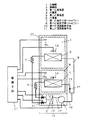
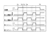
図1は、本発明の実施例1における冷蔵庫の概略図、図2は同実施例のタイムチャートである。
【0054】
20は冷蔵庫箱体であり、上方部に比較的高温の区画である冷蔵室4を、下方部に比較的低温の冷凍室6を配置してあり、例えばウレタンのような断熱材で周囲を断熱して構成している。食品等の収納物の出し入れは図示しない断熱ドアを介して行われる。
【0055】
冷蔵室4は冷蔵保存のために通常3〜5℃で設定されているが、保鮮性向上のため若干低めの温度、例えば−3〜0℃で設定されることもあり、収納物によって、使用者が自由に上記のような温度設定を切り替えることを可能としている場合もある。また、ワインや根野菜等の保鮮のために、例えば10℃前後の若干高めの温度設定とする場合もある。
【0056】
冷凍室6は冷凍保存のために通常−22〜−18℃で設定されているが、保鮮性向上のためより低温の温度、例えば−30〜−25℃で設定されることもある。
【0057】
冷凍サイクル12は圧縮機1と凝縮器2と第一の流路制御手段である第一の電動弁10と第一の減圧手段である第一のキャピラリ7と第一の蒸発器3を順次接続し、第一の電動弁10と第一のキャピラリ7と第一の蒸発器3と並列になるように第二の流路制御手段である第二の電動弁11と第二の減圧手段である第二のキャピラリ8と第二の蒸発器5を接続してある。
【0058】
第一の蒸発器3は冷蔵室4内の、例えば冷蔵室奥面に配設されており、近傍には冷蔵室4の区画内空気を第一の蒸発器3に通過させて循環させる第一の電動ファン13が設けてある。
【0059】
また、第二の蒸発器5は冷凍室6内の、例えば冷凍室奥面に配設されており、近傍には冷凍室6の区画内空気を第二の蒸発器5を通過させて循環させる第二の電動ファン14が設けてある。
【0060】
圧縮機1と凝縮器2と第一の電動弁10と第二の電動弁11は可燃性冷媒を使用した場合に安全性向上の面から冷蔵庫箱体20内での配管接続箇所削減のために機械室15に配設されている。
【0061】
各蒸発器から戻ってくる冷媒は圧縮機吸入管16を通って、圧縮機1内空間へ放出された後、圧縮機吐出管17を通じて吐出される構成である。
【0062】
さらに圧縮機1は例えばインバーターによる回転数制御で冷媒循環量を制御し冷凍能力を変化させることができる能力可変型としてある。
【0063】
また、冷蔵室4と冷凍室6には区画内温度を検知する、例えばサーミスタである温度検知手段Th1,Th2を設けてあり、能力可変型圧縮機1と第一の電動弁10と第二の電動弁11と第一の電動ファン13と第二の電動ファン14とを制御する制御手段C1とを備えている。21は逆止弁で、第二の蒸発器5と圧縮機1の間に介在され、冷媒の逆流を防止している。
【0064】
ここで、第一の電動弁と第二の電動弁と第一のファンと第二のファンの基本動作について説明する。
【0065】
圧縮機運転中、第一の電動弁10は冷蔵室4の温度検知手段が予め設定された所定の温度を超えている場合は開放動作を行い、また予め設定された所定の温度より低い場合は閉止動作を行う。また、第一の電動ファン13も同様に冷蔵室4の温度検知手段が予め設定された所定の温度を超えている場合は運転を行い、また予め設定された所定の温度より低い場合は停止する。
【0066】
また、圧縮機運転中、第二の電動弁11は冷蔵室4の温度検知手段が予め設定された所定の温度より低い場合は開放動作を行い、また予め設定された所定の温度より高い場合は閉止動作を行う。また、第二の電動ファン14も同様に冷蔵室4の温度検知手段が予め設定された所定の温度より低い場合は運転を行い、また予め設定された所定の温度より高い場合は停止する。
【0067】
以上のように構成された冷蔵庫について、冷蔵室4と冷凍室6の冷却タイミングについて図2のタイムチャートをもとに説明する。
【0068】
圧縮機停止中に、冷凍室6内の温度が上昇すると、冷凍室6の温度検知手段が、予め設定された所定の温度を超えることを検知する。制御手段はこの信号を受けて、圧縮機1と第二の電動ファン14を作動し、第二の電動弁11を開放し、第一の電動弁を閉止する(T1)。
【0069】
圧縮機1の動作により吐出された高温高圧の冷媒は、凝縮器2にて放熱して凝縮液化し、第二の電動弁11を経て第二のキャピラリ8に至る。その後、第二のキャピラリ8で第二のサクションライン19と熱交換しながら減圧されて第二の蒸発器5に至る。第二の電動ファン14の作動により冷凍室6内の空気と積極的に熱交換されて冷媒は第二の蒸発器5内で蒸発気化し熱交換された空気はより低温の空気となって吐出され冷凍室6を冷却する。気化した冷媒は、第二のサクションライン19を経て圧縮機1に吸入される。
【0070】
冷凍室6冷却中に冷蔵室4の温度検知手段が予め設定された所定の温度を超えていることを検知すると、第二の電動弁11を閉止し同時に第二の電動ファン14を停止する(T2)。
【0071】
所定時間、第一の電動弁10と第二の電動弁11を閉止し冷媒の流れを遮断する(T2〜T3)。
【0072】
所定時間経過後、第一の電動弁10を開放し第一の電動ファン13を作動する(T3)。
【0073】
冷媒は、第一の電動弁10を経て第一のキャピラリ7に至る。その後、第一のキャピラリ7で第一のサクションライン18と熱交換しながら減圧されて第一の蒸発器3に至る。第一の電動ファン13の作動により冷蔵室4内の空気と積極的に熱交換されて冷媒は第一の蒸発器3内で蒸発気化し熱交換された空気は比較的低温の空気となって吐出され冷蔵室4を冷却する。気化した冷媒は、第一のサクションライン18を経て圧縮機1に吸入される。
【0074】
冷蔵室4冷却中に冷蔵室4の温度検知手段が予め設定された所定の温度より低いことを検知すると、第一の電動弁10を閉止し同時に第一の電動ファン13を停止し、同時に第二の電動弁11を開放し第二の電動ファン14を作動し、冷凍室6の冷却を開始する(T4)。
【0075】
以上の動作を繰り返し、冷媒の流れを切り替えることにより、冷蔵室4と冷凍室6を交互に冷却し、冷蔵室4と冷凍室6の温度検知手段が共に予め設定された所定の温度より低いことを検知すると、圧縮機を停止する(T5)。
【0076】
第一の電動弁10が閉止であり第二の電動弁11が開放である、第二の蒸発器5に冷媒が流入する冷凍室6冷却状態から、第一の電動弁10が開放し第二の電動弁11が閉止となる、第一の蒸発器3に冷媒が流入する冷蔵室4冷却状態に冷媒の流れが切り替わる時、第一の電動弁10と第二の電動弁11を所定時間閉止し(T2〜T3)、冷媒の流れが完全に遮断された状態で圧縮機を運転するために圧縮機内の圧力が通常運転時と比較してかなり低圧となり、第二の蒸発器5内に滞留していた冷媒を第二の蒸発器5から追い出すことが可能となる。
【0077】
その結果、第一の電動弁10が開放となり冷蔵室4冷却状態に切り替わった時(T3)、速やかに第一の蒸発器3に冷媒が供給されるので冷媒循環量不足にならず、効率よく冷蔵室4を冷却することが可能となる。
【0078】
なお、例えば可燃性冷媒を用いる場合には上記の結果より冷媒を効率よく利用することができるので冷蔵室4冷却時に必要冷媒量が増加することがなく冷媒量を削減でき、冷媒漏洩時の危険性を小さくすることが可能となる。
【0079】
(実施の形態2)
実施例1と同一構成についてはその詳細な説明を省略し、同一符号を付す。
【0080】
第一の電動弁10が閉止であり第二の電動弁11が開放である。第二の蒸発器5に冷媒が流入する冷凍室6冷却状態から、第一の電動弁10が開放し第二の電動弁11が閉止となる、第一の蒸発器3に冷媒が流入する冷蔵室4冷却状態に冷媒の流れが切り替わる時、第一の電動弁10と第二の電動弁11を共に閉止する時間(T2〜T3)を制御するタイマーTを備えた制御手段C2を設ける。
【0081】
以上のように構成された冷蔵庫について、冷蔵室4冷却から冷凍室6冷却に切り替わる時の、第一の電動弁10と第二の電動弁11の動作のタイミングについて図2のタイムチャートをもとに説明する。
【0082】
冷凍室6冷却中に冷蔵室4の温度検知手段が予め設定された所定の温度を超えていることを検知すると、第二の電動弁11を閉止し同時に第二の電動ファン14を停止する(T2)。
【0083】
タイマーTにより所定時間、第一の電動弁10と第二の電動弁11を閉止し冷媒の流れを遮断する(T2〜T3)。
【0084】
所定時間経過後、第一の電動弁10を開放し第一の電動ファン13を作動し、冷蔵室4の冷却を開始する(T3)。
【0085】
タイマーTによる制御は、安価であり、制御手段が複雑でなく、且つ容易に設定時間を変更することができるので、最も簡単に冷媒の流れを制御することが可能となる。
【0086】
(実施の形態3)
図4は本発明の実施例3における冷蔵庫の概略図、図5は本発明の実施例3のタイムチャートである。
【0087】
実施例1と同一構成についてはその詳細な説明を省略し、同一符号を付す。
【0088】
第二の蒸発器5の配管温度を検出する温度検知手段Th3を設け、第一の電動弁10が閉止であり第二の電動弁11が開放である。第二の蒸発器5に冷媒が流入する冷凍室6冷却状態から、第一の電動弁10が開放し第二の電動弁11が閉止となる、第一の蒸発器3に冷媒が流入する冷蔵室4冷却状態に冷媒の流れが切り替わる時、第一の電動弁10と第二の電動弁11を前記温度検知手段により所定の温度設定値以上を検知するまで閉止した後、第一の電動弁10を開放し冷蔵室4の冷却を開始する制御手段C3を設ける。
【0089】
以上のように構成された冷蔵庫について、冷蔵室4冷却から冷凍室6冷却に切り替わる時の、第一の電動弁10と第二の電動弁11の動作のタイミングについて図5のタイムチャートをもとに説明する。
【0090】
冷凍室6冷却中、第二の蒸発器5に流入した冷媒は冷凍室6内の空気と積極的に熱交換を行い、比較的低い温度(t1)で蒸発気化している(T6〜T7)。
【0091】
冷凍室6冷却中に冷蔵室4の温度検知手段が予め設定された所定の温度を超えていることを検知すると、第二の電動弁11を閉止する(T7)。
【0092】
第一の電動弁10と第二の電動弁11を共に閉止し、冷媒の流れが完全に遮断された状態で圧縮機1を運転すると第二の蒸発器5内に滞留していた気液二相状態の冷媒は、圧力が下がるために蒸発しながら第二の蒸発器5から圧縮機1へ移動する。
【0093】
その結果、第二の蒸発器に冷媒が残留している間は、第二の蒸発器5の配管温度は冷凍室温度(t2)より低温となる。そして、冷媒の残留量が少なくなるにつれて上昇し冷凍室温度(t2)に近づく(T7〜T8)。
【0094】
第二の蒸発器5の配管温度が、例えば冷凍室温度(t2)と等しくなった時、第二の蒸発器5内に滞留していた冷媒がほとんどなくなったと判断し、第一の電動弁10を開放し冷蔵室4の冷却を開始する(T8)。
【0095】
これにより、冷凍室6冷却から冷蔵室4冷却に切り替わる時、最も効率よく第二の蒸発器5内に滞留していた冷媒を追い出すことができ、冷蔵室4冷却開始時に、速やかに第一の蒸発器3に冷媒を供給できるので冷媒循環量不足にならず、さらに効率よく冷蔵室4を冷却することが可能となる。
【0096】
(実施の形態4)
図6は本発明の実施例4における冷蔵庫の概略図、図7は本発明の実施例4のタイムチャートである。
【0097】
実施例1と同一構成についてはその詳細な説明を省略し、同一符号を付す。
【0098】
圧縮機1に流入する冷媒の圧力を検出する圧力検知手段(P)を設け、第一の電動弁10が閉止であり第二の電動弁11が開放である。第二の蒸発器5に冷媒が流入する冷凍室6冷却状態から、第一の電動弁10が開放し第二の電動弁11が閉止となる。第一の蒸発器3に冷媒が流入する冷蔵室4冷却状態に冷媒の流れが切り替わる時、第一の電動弁10と第二の電動弁11を前記圧力検知手段により所定の圧力設定値以下を検知するまで閉止した後、第一の電動弁10を開放し冷蔵室4の冷却を開始する制御手段C4を設ける。
【0099】
以上のように構成された冷蔵庫について、冷蔵室4冷却から冷凍室6冷却に切り替わる時の、第一の電動弁10と第二の電動弁11の動作のタイミングについて図7のタイムチャートをもとに説明する。
【0100】
冷凍室6冷却中、圧縮機1に流入する冷媒の圧力は比較的低圧(p1)である(T9〜T10)。
【0101】
冷凍室6冷却中に冷蔵室4の温度検知手段が予め設定された所定の温度を超えていることを検知すると、第二の電動弁11を閉止する(T10)。
【0102】
第一の電動弁10と第二の電動弁11を共に閉止し、冷媒の流れを完全に遮断された状態で圧縮機1を運転すると圧縮機1に流入する冷媒の圧力は急速に低下し、最終的に0MPaに近づく。しかし、この状態で圧縮機1の運転を繰り返すと圧縮機1に損傷をきたす恐れがあるので、圧縮機1に流入する冷媒の圧力検知手段が例えば0.02MPa以下を検知した時、第一の電動弁10を開放し冷蔵室4の冷却を開始する。
【0103】
これにより、冷凍室6冷却から冷蔵室4冷却に切り替わる時に圧縮機1にかかる負担を低減でき、圧縮機1の損傷を防ぐことが可能となる。
【0104】
(実施の形態5)
図8は本発明の実施例5における冷蔵庫の概略図、図9は本発明の実施例5のタイムチャートである。
【0105】
実施例1と同一構成についてはその詳細な説明を省略し、同一符号を付す。
【0106】
第一の電動弁10が閉止であり第二の電動弁11が開放である、第二の蒸発器5に冷媒が流入する冷凍室6冷却状態から、第一の電動弁10が開放し第二の電動弁11が閉止となる、第一の蒸発器3に冷媒が流入する冷蔵室4冷却状態に冷媒の流れが切り替わる時、第二の電動弁11を閉止し、第一の電動弁10を断続的に所定時間開閉した後、第一の電動弁10を開放し冷蔵室4の冷却を開始する制御手段C5を設ける。
【0107】
以上のように構成された冷蔵庫について、冷蔵室4冷却から冷凍室6冷却に切り替わる時の、第一の電動弁10と第二の電動弁11の動作のタイミングについて、圧縮機1に流入する冷媒の圧力変化を参考に図9のタイムチャートをもとに説明する。
【0108】
冷凍室6冷却中、圧縮機1に流入する冷媒の圧力は比較的低圧(p3)である(T12〜13)。
【0109】
冷凍室6冷却中に冷蔵室4の温度検知手段が予め設定された所定の温度を超えていることを検知すると、第二の電動弁11を閉止する(T13)。
【0110】
第一の電動弁10と第二の電動弁11を共に閉止し、冷媒の流れが完全に遮断された状態で圧縮機1を運転すると圧縮機1に流入する冷媒の圧力は低下を始める(T13〜14)。
【0111】
所定時間経過後、第一の電動弁10を開放する。この時、圧縮機1に流入する圧力は運転中の圧力(p3)から(p4)に低下している(T14)。
【0112】
第一の電動弁10を開放すると、閉塞していた冷凍サイクルが開となり冷媒が循環し始めるので圧縮機1に流入する冷媒の圧力は上昇する(T14〜T15)。
【0113】
所定時間経過後、第一の電動弁10を閉止する。この時、圧縮機1に流入する冷媒の圧力は(p4)から(p5)にやや上昇している(T15)。
【0114】
第一の電動弁10を閉止すると、冷媒の流れが完全に遮断された状態で圧縮機1を運転するために圧縮機1に流入する冷媒の圧力は再び低下を始める。
【0115】
以上の動作を繰り返し、所定時間経過後、第一の電動弁10を開放し冷蔵室4の冷却を開始する。この時の、圧縮機1に流入する冷媒の圧力は冷凍室6冷却中の圧力(p3)から(p6)に低下している(T17)。
【0116】
これにより、冷凍室6冷却から冷蔵室4冷却に切り替わる時に圧縮機1に流入する冷媒の圧力を段階的に低下させることができるので、圧力の急低下による圧縮機1への負担を低減し、損傷を防ぐことが可能となる。
【0117】
また、その結果、第一の電動弁10と第二の電動弁11を共に完全に閉止して第二の蒸発器5内に滞留した冷媒を追い出す手段と比較して、より長い間第二の蒸発器5内に滞留した冷媒を追い出すことができるので、さらに効率よく冷蔵室4の冷却を行うことが可能となる。
【0118】
(実施の形態6)
図10は本発明の実施例6における冷蔵庫の概略図、図11は本発明の実施例6のタイムチャートである。
【0119】
実施例1と同一構成についてはその詳細な説明を省略し、同一符号を付す。
【0120】
冷蔵室4と冷凍室6の図示しない温度検知手段が共に所定の温度設定値以下を検知すると、第一の電動弁10と第二の電動弁11を閉止し、所定時間経過後圧縮機1を停止させ、圧縮機停止中は第一の電動弁10と第二の電動弁11を常に閉止する制御手段C6を設ける。
【0121】
以上のように構成された冷蔵庫について、圧縮機が停止する時の第一の電動弁10と第二の電動弁11の動作について、図11のタイムチャートをもとに説明する。
【0122】
例えば冷凍室6冷却中、冷蔵室4と冷凍室6の図示しない温度検知手段が共に所定の温度設定値以下を検知すると、第一の電動弁10と第二の電動弁11を閉止する(T18)。
【0123】
所定時間経過後、圧縮機1を停止する。(T19)。
【0124】
圧縮機1停止中、第一の電動弁10と第二の電動弁11は常に閉止する(T19〜T20)。
【0125】
圧縮機1停止中に、例えば冷凍室6の温度検知手段Th2が所定の温度設定値以上を検知すると、圧縮機1を作動させ、同時に第二の電動弁11を開放し冷凍室6の冷却を開始する(T20)。
【0126】
圧縮機1を停止する前
に、第一の電動弁10と第二の電動弁11を閉止し、冷媒の流れが完全に遮断された状態で圧縮機1を所定時間運転するので、圧縮機1に流入する冷媒の圧力は低下し第一の蒸発器3と第二の蒸発器5に滞留している冷媒を圧縮機側へ追い出すことが可能となる。
【0127】
また、圧縮機1停止中は冷凍室の温度が例えば約−18℃と最も低いために冷凍室6内に配設された第二の蒸発器5の圧力が冷凍サイクル内で最も低圧となり、凝縮器2内の高圧冷媒が第二の蒸発器5内へ移動し滞留するので冷却開始時に例えば第二の蒸発器5に速やかに冷媒を供給できず効率低下の原因となっていたが、圧縮機1停止中は第一の電動弁10と第二の電動弁11を常に閉止するために第一の蒸発器3と第二の蒸発器5への冷媒の移動は妨げられ、圧縮機1起動時に速やかに例えば第二の蒸発器に冷媒を供給することができるので冷媒循環量不足にならず、効率よく冷凍室を冷却することが可能となる。
【0128】
尚、実施例においては第一の流路制御手段と第二の流路制御手段とがそれぞれ独立して説明したが、三方弁を用いても同様の効果が得られる。
【0129】
【発明の効果】
本発明は、以上説明したような形態で実施され、以下に記載されるような効果を奏する。
【0130】
第一の流路制御手段が閉止であり第二の流路制御手段が開放で、第二の蒸発器に可燃性冷媒が流入する状態から、第一の流路制御手段が開放し第二の流路制御手段が閉となり、第一の蒸発器に可燃性冷媒が流入する状態に冷媒の流れが切り替わる時、第一の流路制御手段と第二の流路制御手段をともに所定時間閉止し、冷媒の流れが完全に遮断された状態で圧縮機を運転するために圧縮機内の圧力が通常運転時と比較してかなり低圧となり、第二の蒸発器内に滞留していた可燃性冷媒を第二の蒸発器から追い出すことが可能となる。
【0131】
その結果、第一の流路制御手段が開放となり切り替わった時、速やかに第一の蒸発器に冷媒が供給されるので冷媒循環量不足にならず、効率よく冷蔵室を冷却することが可能となる。
【0132】
また、可燃性冷媒を効率よく利用することができるので必要冷媒量が増加することがなく冷媒量を削減でき、冷媒漏洩時の危険性を小さくすることが可能となる。
【0133】
また、第二の蒸発器の配管温度を検出する温度検知手段を設け、この温度検知手段により所定の温度設定値以上を検知するまで閉止した後、第一の流路制御手段を開放して冷却を開始することにより、最も効率よく第二の蒸発器内に滞留していた冷媒を追い出すことができ、冷却開始時に、速やかに第一の蒸発器に冷媒を供給できるので冷媒循環量不足にならず、さらに効率よく冷却することが可能となる。
【0134】
また、第一の流路制御手段が閉止であり第二の流路制御手段が開放である第二の蒸発器5に冷媒が流入する状態から、第一の流路制御手段が開放し第二の流路制御手段が閉止となる第一の蒸発器3に冷媒が流入する冷却状態に冷媒の流れが切り替わる時、第二の流路制御手段を閉止し、第一の流路制御手段を断続的に所定時間開閉した後、第一の流路制御手段を開放し冷却を開始することにより、切り替わる時に圧縮機に流入する冷媒の圧力を段階的に低下させることができるので、圧力の急低下による圧縮機への負担を低減し、損傷を防ぐことが可能となる。
【0135】
また、その結果、第一の流路制御手段と第二の流路制御手段を共に閉止して第二の蒸発器内に滞留した冷媒を追い出す手段と比較して、より長い間第二の蒸発器内に滞留した冷媒を追い出すことができるので、さらに効率よく冷却を行うことが可能となる。
【0136】
また、冷蔵室と冷凍室を備えた箱体と、圧縮機、凝縮器、この凝縮器からの冷媒を分流する第一の流路制御手段と第二の流路制御手段、前記第一の流路制御手段の下流側に連結された第一の減圧手段、この第一の減圧手段と連結された第一の蒸発器、前記第二の流路制御手段の下流側に連結された第二の減圧手段、及び、この第二の減圧手段と連結された第二の蒸発器を備えた冷凍サイクルとを有し、前記第一の冷却器により前記冷蔵室を冷却し、前記第二の冷却器により前記冷凍室を冷却するものであって、前記冷媒を可燃性冷媒とし、前記圧縮機は、吸入冷媒が圧縮機内空間に放出される低圧容器型でかつインバーターによる回転数制御で冷媒循環量を変化できる能力可変型であり、前記第一の流路制御手段と第二の流路制御手段とを機械室内に配設する三方弁で構成したものであって、前記冷蔵室及び前記冷凍室の温度検知手段がともに設定温度以下になったとき、前記三方弁を閉として前記圧縮機を停止し、前記圧縮機の停止中は前記三方弁を閉としたまま前記冷媒の前記第一、第二の蒸発器への移動を防止する冷蔵庫であるので冷媒を効率よく利用することができるので可燃性冷媒の冷媒量を削減でき、冷媒漏洩時の危険性を小さくすることが可能となる。
【0137】
また、第一の流路制御手段と第二の流路制御手段を閉止し、所定時間経過後圧 縮機を停止させることにより、第一の蒸発器と第二の蒸発器に滞留している冷媒を圧縮機側へ追い出すことが可能となる。
【図面の簡単な説明】
【図1】本発明の請求項1の実施例における冷蔵庫の概略図
【図2】本発明の請求項1と請求項2の実施例における冷蔵庫のタイムチャート
【図3】本発明の請求項2の実施例における冷蔵庫の概略図
【図4】本発明の請求項3の実施例における冷蔵庫の概略図
【図5】本発明の請求項3の実施例における冷蔵庫のタイムチャート
【図6】本発明の請求項4の実施例における冷蔵庫の概略図
【図7】本発明の請求項4の実施例における冷蔵庫のタイムチャート
【図8】本発明の請求項5の実施例における冷蔵庫の概略図
【図9】本発明の請求項5の実施例における冷蔵庫のタイムチャート
【図10】本発明の請求項6の実施例における冷蔵庫の概略図
【図11】本発明の請求項6の実施例における冷蔵庫のタイムチャート
【図12】従来の冷蔵庫の概略図
【符号の説明】
1 圧縮機
2 凝縮器
3 第一の蒸発器
5 第二の蒸発器
7 第一の減圧手段(キャピラリ)
8 第二の減圧手段(キャピラリ)
10 第一の流路制御手段(電動弁)
11 第二の流路制御手段(電動弁)
C1,C2,C3,C4,C5,C6 制御手段
T タイマー
Th3 温度検知手段
P 圧力検知手段[0001]
TECHNICAL FIELD OF THE INVENTION
The present invention relates to a cooling system used for a refrigerator or the like.
[0002]
[Prior art]
FIG. 12 shows a schematic diagram of a refrigerator disclosed in Japanese Patent Publication No. 62-22396 as an example of a conventional cooling cycle and a refrigerator.
[0003]
1 is a constant speed compressor, 2 is a condenser, 3 is a first evaporator disposed in the
[0004]
[0005]
[0006]
The operation of the conventional refrigerator configured as described above will be described below.
[0007]
The operation of the refrigeration cycle is performed as follows. First, the refrigerant compressed by the
[0008]
Each room is cooled by the heat exchange between the
[0009]
The cooling operation of the refrigerator is performed as follows by temperature detecting means and control means of each room (not shown).
[0010]
When each of the temperature detecting means of the
[0011]
Thereby, the refrigerant does not flow into the
[0012]
When the
[0013]
Thereby, the refrigerant flows into the
[0014]
As described above, since the refrigerant supply time to the evaporator is distributed to the refrigerating
[0015]
Further, the check valve 9 prevents the refrigerant from flowing into the
[0016]
In addition, when cooling the
[0017]
[Problems to be solved by the invention]
In the above-mentioned conventional refrigerator, the refrigerating
[0018]
However, when the
[0019]
Due to the above factors, the required amount of refrigerant increases, and when a flammable refrigerant is used, there is a large risk of refrigerant leakage and a problem.
[0020]
Further, since the temperature of the
[0021]
The present invention solves the above-described conventional problems, and provides a refrigerator capable of saving energy by reducing the amount of refrigerant and improving the efficiency of a cooling system that performs cooling by switching between a refrigerator compartment and a freezer compartment. The purpose is to:
[0022]
[Means for Solving the Problems]
The cooling system according to
[0023]
Thereby, when switching from the cooling state of the freezing compartment into which the refrigerant has flowed into the second evaporator to the cooling state of the refrigerator compartment into which the refrigerant has flowed into the first evaporator, the two flow control means are closed for a predetermined time. Therefore, since the compressor is operated in a state where the flow of the refrigerant is completely shut off, the pressure in the compressor becomes lower than that in the normal operation, so that the refrigerant remaining in the second evaporator is removed. It can be driven out of the second evaporator.
[0024]
As a result, efficient operation can be achieved without shortage of the circulation amount of the refrigerant.
[0025]
In addition, the efficient use of refrigerant can reduce the amount of refrigerant compared to the conventional method,ofThe danger due to refrigerant leakage can be reduced.
[0027]
AlsoWhen the compressor is operated in a state where the flow of the refrigerant is completely shut off, the refrigerant in the gas-liquid two-layer state that has stayed in the second evaporator evaporates due to a decrease in pressure, and the second evaporator evaporates. Since the refrigerant moves to the compressor, while the refrigerant remains in the second evaporator, the pipe temperature of the second evaporator becomes low.
[0028]
That is, the refrigerant can be quickly supplied to the cooling of the first evaporator, so that the refrigerant circulation amount does not become insufficient.
[0029]
Claims of the invention2The cooling system described above is connected to a compressor, a condenser, a first flow path control means, a second flow path control means, and a first flow path control means for dividing a refrigerant from the condenser. First decompression means, a first evaporator connected to the first decompression means, a second decompression means connected to the second flow path control means, and a second decompression means A second evaporator connected to the means, wherein the refrigerant is a flammable refrigerant, the flow path of the first flow path control means is closed, and the flow path of the second flow path control means is open. From the state where the refrigerant is flowing into the second evaporator, the flow path of the first flow path control means is open and the flow path of the second flow path control means is closed and the first flow path is closed. When switching the flow of the refrigerant to a state where the refrigerant flows into the evaporator, the first flow control valve is intermittently closed for a predetermined time, and then the first flow is controlled. Those having a control means for the passage of the control means open.
[0030]
By intermittently operating the compressor in this manner, the pressure of the refrigerant flowing through the compressor can be reduced in a stepwise manner, so that damage to the compressor due to a sudden drop in pressure can be prevented.
[0031]
Further, efficient use of the refrigerant can reduce the amount of the refrigerant as compared with the related art, so that danger due to refrigerant leakage of the flammable refrigerant can be reduced.
[0032]
Claims of the invention3The refrigerator according to the present invention includes a box having a refrigerator compartment and a freezer compartment, a compressor, a condenser, a first flow path control means and a second flow path control means for dividing the refrigerant from the condenser, One flow path control meansDownstream ofA first decompression means connected to the first evaporator connected to the first decompression means, a second decompression means connected to the downstream side of the second flow path control means, and Having a refrigeration cycle with a second evaporator connected to the second decompression means,The first cooler cools the refrigerator compartment, the second cooler cools the freezer compartment, wherein the refrigerant is a flammable refrigerant,The compressor is a low-pressure container type in which the suction refrigerant is discharged into the internal space of the compressor, and is a variable capacity type capable of changing the refrigerant circulation amount by controlling the rotation speed by an inverter. Flow path control means and machine room installedComposed of three-way valveWhen both the temperature detection means of the refrigerator compartment and the freezer compartment fall below a set temperature,Three-way valveTo close the compressor and stop the compressorPrevents the refrigerant from moving to the first and second evaporators while the three-way valve is closedTo do.
[0033]
As a result, when the compressor is stopped, the pressure in the second evaporator becomes the lowest in the refrigeration cycle because the temperature of the freezer is the lowest, and the high-pressure refrigerant in the condenser moves into the second evaporator. Since the refrigerant stayed at the start of cooling, the refrigerant could not be quickly supplied to the second evaporator, causing a decrease in efficiency.However, during the stop of the compressor, the first motor-operated valve and the second motor-operated valve were closed. The movement of the refrigerant to the first evaporator and the second evaporator is prevented, and the refrigerant can be supplied to the second evaporator quickly at the time of starting the compressor. It becomes possible to cool the freezer compartment.
[0034]
In the refrigerator according to
[0036]
BEST MODE FOR CARRYING OUT THE INVENTION
The invention described in
[0041]
Thus, when the flow paths of the first flow path control means and the second flow path control means are closed and the compressor is operated in a state in which the flow of the refrigerant is completely shut off, the refrigerant stays in the second evaporator. The refrigerant in the gas-liquid two-phase state that has been moved from the second evaporator to the compressor while evaporating due to a decrease in pressure, so that while the refrigerant remains in the second evaporator, the second The pipe temperature of the evaporator is lower than the freezing room temperature. Then, as the residual amount of the refrigerant decreases, the temperature rises and approaches the freezing room temperature.
[0042]
When the pipe temperature of the second evaporator becomes equal to, for example, the freezing room temperature, it is determined that the refrigerant remaining in the second evaporator has almost disappeared, and the first flow path control means is opened to refrigerate. Start cooling the chamber.
[0043]
Thereby, when the operation of the evaporator is switched, the refrigerant that has stayed in the second evaporator can be driven out most efficiently, and the refrigerant can be supplied to the first evaporator quickly, so that the refrigerant circulation amount becomes insufficient. In addition, it is possible to operate more efficiently.
[0044]
Of the present inventionClaim 2The invention described in the above is connected to a compressor, a condenser, a first flow path control means, a second flow path control means for dividing the refrigerant from the condenser, and the first flow path control means First decompression means, a first evaporator connected to the first decompression means, a second decompression means connected to the second flow path control means, and a second decompression means A second evaporator connected to the means, wherein the refrigerant is a flammable refrigerant, the flow path of the first flow path control means is closed, and the flow path of the second flow path control means is open. From the state where the refrigerant is flowing into the second evaporator, the flow path of the first flow path control means is open and the flow path of the second flow path control means is closed and the first flow path is closed. When switching the flow of the refrigerant to a state where the refrigerant flows into the evaporator, after the first flow path control valve is intermittently closed for a predetermined time, the first flow path control is performed. Those having a control means for the flow path of the stage and opened.
[0045]
This makes it possible to gradually reduce the pressure of the refrigerant flowing into the compressor when switching from freezer compartment cooling to refrigerator compartment cooling, thereby reducing the load on the compressor due to a sudden drop in pressure and preventing damage. Becomes possible.
[0046]
Further, as a result, the second evaporating operation is performed for a longer time as compared with the case where both the first flow path control means and the second flow path control means are closed and the refrigerant that has accumulated in the second evaporator is expelled. Since the refrigerant staying in the vessel can be expelled, it is possible to more efficiently cool the refrigerator compartment.
[0047]
In addition, since the refrigerant can be used efficiently from the above results, the amount of the flammable refrigerant can be reduced, and the risk of refrigerant leakage can be reduced.
[0048]
Of the present inventionClaim 3The invention described in the above, a box having a refrigerator compartment and a freezer compartment, a compressor, a condenser, a first flow path control means and a second flow path control means for diverting the refrigerant from the condenser, First flow path control meansDownstream ofA first decompression means connected to the first evaporator connected to the first decompression means, a second decompression means connected to the downstream side of the second flow path control means, and Having a refrigeration cycle with a second evaporator connected to the second decompression means,The first cooler cools the refrigerator compartment, the second cooler cools the freezer compartment, wherein the refrigerant is a flammable refrigerant,The compressor is a low-pressure container type in which the suction refrigerant is discharged into the internal space of the compressor, and is a variable capacity type capable of changing the refrigerant circulation amount by controlling the rotation speed by an inverter. Flow path control means and machine room installedComposed of three-way valveWhen both the temperature detection means of the refrigerator compartment and the freezer compartment fall below a set temperature,Three-way valveTo close the compressor and stop the compressorDuring the stop of the operation, the refrigerant is prevented from moving to the first and second evaporators while the three-way valve is closed.It is a refrigerator.
[0049]
While the compressor is stopped, the pressure in the second evaporator becomes the lowest in the refrigeration cycle because the temperature of the freezing room is the lowest, and the high-pressure refrigerant in the condenser moves into the second evaporator and stays there, so cooling is performed. At the start, the refrigerant could not be quickly supplied to the second evaporator, causing a decrease in efficiency.However, during the stop of the compressor, the first evaporator and the second The movement of the refrigerant to the evaporator and the second evaporator is prevented, and the refrigerant can be supplied to the second evaporator quickly at the time of starting the compressor. It is possible to do.
In addition, since the refrigerant can be used efficiently, the amount of the flammable refrigerant can be reduced, and the risk of leakage of the refrigerant can be reduced.
[0050]
Of the present inventionClaim 4In the invention described in the above, before stopping the compressor, the first flow path control means and the second flow path control means are closed, and the compressor is operated for a predetermined time while the flow of the refrigerant is completely shut off. Therefore, the pressure of the refrigerant flowing into the compressor decreases, and the refrigerant remaining in the first evaporator and the second evaporator can be expelled to the compressor side.
[0052]
Hereinafter, an embodiment of the present invention will be described with reference to FIGS. Detailed descriptions of the same components as those of the conventional example are omitted, and the same reference numerals are given.
[0053]
(Embodiment 1)
FIG. 1 is a schematic diagram of a refrigerator in
[0054]
[0055]
The
[0056]
The
[0057]
The
[0058]
The
[0059]
The
[0060]
The
[0061]
The refrigerant returning from each evaporator passes through the
[0062]
Further, the
[0063]
The
[0064]
Here, the basic operation of the first motor-operated valve, the second motor-operated valve, the first fan, and the second fan will be described.
[0065]
During the operation of the compressor, the first motor-operated
[0066]
Further, during the operation of the compressor, the second motor-operated
[0067]
With respect to the refrigerator configured as described above, the cooling timing of the
[0068]
When the temperature in the freezing
[0069]
The high-temperature and high-pressure refrigerant discharged by the operation of the
[0070]
When the temperature detecting means of the
[0071]
For a predetermined time, the first motor-operated
[0072]
After a lapse of a predetermined time, the first
[0073]
The refrigerant reaches the
[0074]
When the temperature detecting means of the
[0075]
By repeating the above operation and switching the flow of the refrigerant, the
[0076]
When the first
[0077]
As a result, when the first motor-operated
[0078]
In the case of using a flammable refrigerant, for example, the refrigerant can be efficiently used based on the above results. Therefore, the amount of refrigerant can be reduced without increasing the required amount of refrigerant when cooling the
[0079]
(Embodiment 2)
Detailed descriptions of the same components as those of the first embodiment are omitted, and the same reference numerals are given.
[0080]
The first motor-operated
[0081]
Regarding the refrigerator configured as described above, the operation timing of the first motor-operated
[0082]
When the temperature detecting means of the
[0083]
The first motor-operated
[0084]
After a lapse of a predetermined time, the first
[0085]
The control by the timer T is inexpensive, the control means is not complicated, and the set time can be easily changed, so that the flow of the refrigerant can be controlled most easily.
[0086]
(Embodiment 3)
FIG. 4 is a schematic diagram of a refrigerator according to the third embodiment of the present invention, and FIG. 5 is a time chart of the third embodiment of the present invention.
[0087]
Detailed descriptions of the same components as those of the first embodiment are omitted, and the same reference numerals are given.
[0088]
A temperature detecting means Th3 for detecting a pipe temperature of the
[0089]
Regarding the refrigerator configured as described above, the timing of the operation of the first motor-operated
[0090]
During cooling of the freezing
[0091]
When the temperature detecting means of the
[0092]
When the
[0093]
As a result, while the refrigerant remains in the second evaporator, the pipe temperature of the
[0094]
When the pipe temperature of the
[0095]
Thereby, when switching from the freezing
[0096]
(Embodiment 4)
FIG. 6 is a schematic diagram of a refrigerator according to the fourth embodiment of the present invention, and FIG. 7 is a time chart of the fourth embodiment of the present invention.
[0097]
Detailed descriptions of the same components as those of the first embodiment are omitted, and the same reference numerals are given.
[0098]
A pressure detecting means (P) for detecting the pressure of the refrigerant flowing into the
[0099]
Regarding the refrigerator configured as described above, the operation timing of the first motor-operated
[0100]
During the cooling of the freezing
[0101]
When the temperature detecting means of the
[0102]
When the first motor-operated
[0103]
This reduces the load on the
[0104]
(Embodiment 5)
FIG. 8 is a schematic diagram of a refrigerator according to the fifth embodiment of the present invention, and FIG. 9 is a time chart of the fifth embodiment of the present invention.
[0105]
Detailed descriptions of the same components as those of the first embodiment are omitted, and the same reference numerals are given.
[0106]
When the first
[0107]
Regarding the refrigerator configured as described above, the timing of the operation of the first motor-operated
[0108]
During cooling of the freezing
[0109]
When the temperature detecting means of the
[0110]
When the first motor-operated
[0111]
After a lapse of a predetermined time, the first motor-operated
[0112]
When the first motor-operated
[0113]
After a lapse of a predetermined time, the first motor-operated
[0114]
When the first motor-operated
[0115]
The above operation is repeated, and after a lapse of a predetermined time, the first motor-operated
[0116]
Thereby, the pressure of the refrigerant flowing into the
[0117]
As a result, the first motor-operated
[0118]
(Embodiment 6)
FIG. 10 is a schematic diagram of a refrigerator according to the sixth embodiment of the present invention, and FIG. 11 is a time chart of the sixth embodiment of the present invention.
[0119]
Detailed descriptions of the same components as those of the first embodiment are omitted, and the same reference numerals are given.
[0120]
When the temperature detecting means (not shown) of the
[0121]
The operation of the first motor-operated
[0122]
For example, during cooling of the
[0123]
After a lapse of a predetermined time, the
[0124]
While the
[0125]
If, for example, the temperature detecting means Th2 of the freezing
[0126]
Before stopping
Since the first motor-operated
[0127]
Further, while the
[0128]
In the embodiment, the first flow path control means and the second flow path control means have been described independently, but the same effect can be obtained by using a three-way valve.
[0129]
【The invention's effect】
The present invention is implemented in the form described above, and has the following effects.
[0130]
The first flow path control means is closed, the second flow path control means is open, and the second evaporatorFlammableFrom the state where the refrigerant flows, the first flow path control means is opened and the second flow path control means is closed, and the first evaporator is closed.FlammabilityWhen the flow of the refrigerant is switched to a state in which the refrigerant flows, both the first flow path control means and the second flow path control means are closed for a predetermined time, and the compressor is operated in a state where the flow of the refrigerant is completely shut off. The pressure inside the compressor became considerably lower than that during normal operation, and remained in the second evaporator.FlammabilityThe refrigerant can be driven out of the second evaporator.
[0131]
As a result, when the first flow path control means is opened and switched, the refrigerant is quickly supplied to the first evaporator, so that the refrigerant circulation amount is not insufficient, and the refrigerator compartment can be efficiently cooled. Become.
[0132]
Also,FlammabilitySince the refrigerant can be used efficiently, the amount of the refrigerant can be reduced without increasing the required refrigerant amount, and the danger at the time of refrigerant leakage can be reduced.
[0133]
Further, a temperature detecting means for detecting a pipe temperature of the second evaporator is provided. After the temperature detecting means is closed until a predetermined temperature set value or more is detected, the first flow path controlling means is opened and cooled. By starting, the refrigerant that has accumulated in the second evaporator can be driven out most efficiently, and when the cooling starts, the refrigerant can be quickly supplied to the first evaporator, so that if the refrigerant circulation amount is insufficient, And cooling can be performed more efficiently.
[0134]
Further, from the state where the refrigerant flows into the
[0135]
Further, as a result, the second evaporator is closed for a longer time as compared with the means for closing both the first flow path control means and the second flow path control means to expel the refrigerant accumulated in the second evaporator. Since the refrigerant staying in the vessel can be expelled, cooling can be performed more efficiently.
[0136]
Also,A box having a refrigerator compartment and a freezer compartment, a compressor, a condenser, first flow path control means and second flow path control means for dividing the refrigerant from the condenser, and the first flow path control A first decompression means connected to the downstream side of the means, a first evaporator connected to the first decompression means, and a second decompression means connected to the downstream side of the second flow path control means And a refrigeration cycle including a second evaporator connected to the second pressure reducing means, wherein the first refrigerator cools the refrigerator compartment, and the second refrigerator cools the refrigerator. The refrigerant is used for cooling a freezing room, wherein the refrigerant is a flammable refrigerant, and the compressor is a low-pressure container type in which a suction refrigerant is discharged into a space inside the compressor, and can change a refrigerant circulation amount by controlling a rotation speed by an inverter. A variable capacity type, wherein the first flow path control means and the second flow path control means When the temperature detecting means of the refrigerator compartment and the freezing compartment both become lower than a set temperature, the compressor is stopped by closing the three-way valve, and the compressor is stopped. While the three-way valve is closed, the refrigerator is a refrigerator that prevents the refrigerant from moving to the first and second evaporators while the three-way valve is closed. Can be reduced, and the danger at the time of refrigerant leakage can be reduced.
[0137]
Also,The first flow path control means and the second flow path control means are closed, and the pressure By stopping the compressor, it is possible to expel the refrigerant remaining in the first evaporator and the second evaporator to the compressor side.
[Brief description of the drawings]
FIG. 1 is a schematic diagram of a refrigerator according to an embodiment of the present invention.
FIG. 2 is a time chart of the refrigerator according to the first and second embodiments of the present invention.
FIG. 3 is a schematic view of a refrigerator according to a second embodiment of the present invention.
FIG. 4 is a schematic view of a refrigerator according to a third embodiment of the present invention.
FIG. 5 is a time chart of a refrigerator according to the third embodiment of the present invention.
FIG. 6 is a schematic view of a refrigerator according to a fourth embodiment of the present invention.
FIG. 7 is a time chart of the refrigerator according to the fourth embodiment of the present invention.
FIG. 8 is a schematic view of a refrigerator according to a fifth embodiment of the present invention.
FIG. 9 is a time chart of the refrigerator in the embodiment of
FIG. 10 is a schematic view of a refrigerator according to a sixth embodiment of the present invention.
FIG. 11 is a time chart of a refrigerator according to the sixth embodiment of the present invention.
FIG. 12 is a schematic diagram of a conventional refrigerator.
[Explanation of symbols]
1 compressor
2 condenser
3 First evaporator
5 Second evaporator
7 First decompression means (capillary)
8 Second decompression means (capillary)
10 First flow path control means (motorized valve)
11 Second flow control means (motorized valve)
C1, C2, C3, C4, C5, C6 control means
T timer
Th3 temperature detection means
P Pressure detection means
Claims (4)
Priority Applications (1)
| Application Number | Priority Date | Filing Date | Title |
|---|---|---|---|
| JP16329699A JP3576040B2 (en) | 1999-06-10 | 1999-06-10 | Cooling systems and refrigerators |
Applications Claiming Priority (1)
| Application Number | Priority Date | Filing Date | Title |
|---|---|---|---|
| JP16329699A JP3576040B2 (en) | 1999-06-10 | 1999-06-10 | Cooling systems and refrigerators |
Publications (3)
| Publication Number | Publication Date |
|---|---|
| JP2000346526A JP2000346526A (en) | 2000-12-15 |
| JP3576040B2 true JP3576040B2 (en) | 2004-10-13 |
| JP2000346526A5 JP2000346526A5 (en) | 2004-11-25 |
Family
ID=15771141
Family Applications (1)
| Application Number | Title | Priority Date | Filing Date |
|---|---|---|---|
| JP16329699A Expired - Lifetime JP3576040B2 (en) | 1999-06-10 | 1999-06-10 | Cooling systems and refrigerators |
Country Status (1)
| Country | Link |
|---|---|
| JP (1) | JP3576040B2 (en) |
Cited By (2)
| Publication number | Priority date | Publication date | Assignee | Title |
|---|---|---|---|---|
| CN103423944A (en) * | 2013-09-04 | 2013-12-04 | 合肥美的电冰箱有限公司 | Refrigerator and control method thereof |
| CN106091457B (en) * | 2016-05-25 | 2019-05-17 | 合肥华凌股份有限公司 | Refrigeration system and its control method and control device, refrigerator |
Families Citing this family (9)
| Publication number | Priority date | Publication date | Assignee | Title |
|---|---|---|---|---|
| KR20020024883A (en) * | 2000-09-27 | 2002-04-03 | 구자홍 | Fluid flowing backward preventing apparatus in refrigerator |
| JP2005257236A (en) * | 2004-03-15 | 2005-09-22 | Sanyo Electric Co Ltd | Freezing device |
| KR100642709B1 (en) * | 2004-03-19 | 2006-11-10 | 산요덴키가부시키가이샤 | Refrigerator |
| JP2007010220A (en) * | 2005-06-30 | 2007-01-18 | Sanyo Electric Co Ltd | Refrigerating unit and refrigerator comprising the same |
| CN103388920B (en) * | 2013-08-15 | 2015-07-15 | 湖北美的电冰箱有限公司 | Refrigerating system and refrigerator provided with same |
| KR102223622B1 (en) | 2013-12-02 | 2021-03-08 | 삼성전자주식회사 | Cooling apparatus |
| DE102014217672A1 (en) * | 2014-09-04 | 2016-03-10 | BSH Hausgeräte GmbH | Refrigerating appliance and chiller for it |
| CN105972915A (en) * | 2016-05-25 | 2016-09-28 | 合肥华凌股份有限公司 | Control method and control device for refrigeration system, and refrigerator |
| JP2022179968A (en) * | 2021-05-24 | 2022-12-06 | 株式会社デンソー | Refrigeration cycle device |
-
1999
- 1999-06-10 JP JP16329699A patent/JP3576040B2/en not_active Expired - Lifetime
Cited By (2)
| Publication number | Priority date | Publication date | Assignee | Title |
|---|---|---|---|---|
| CN103423944A (en) * | 2013-09-04 | 2013-12-04 | 合肥美的电冰箱有限公司 | Refrigerator and control method thereof |
| CN106091457B (en) * | 2016-05-25 | 2019-05-17 | 合肥华凌股份有限公司 | Refrigeration system and its control method and control device, refrigerator |
Also Published As
| Publication number | Publication date |
|---|---|
| JP2000346526A (en) | 2000-12-15 |
Similar Documents
| Publication | Publication Date | Title |
|---|---|---|
| US9909786B2 (en) | Refrigerant distribution apparatus and methods for transport refrigeration system | |
| US6598410B2 (en) | Refrigerator with a plurality of parallel refrigerant passages | |
| KR101314622B1 (en) | Controlling method for the refrigerator | |
| KR20010051119A (en) | Refrigerator | |
| JP3576040B2 (en) | Cooling systems and refrigerators | |
| EP3179182A1 (en) | Refrigerator and method of controlling the same | |
| JP3461736B2 (en) | refrigerator | |
| JP4178646B2 (en) | refrigerator | |
| JP3847499B2 (en) | Two-stage compression refrigeration system | |
| JP2000346526A5 (en) | ||
| JP4021209B2 (en) | refrigerator | |
| JP2006125843A (en) | Cooling cycle and refrigerator | |
| JP3404313B2 (en) | refrigerator | |
| JP2000266444A (en) | Refrigerator | |
| JP2003207250A (en) | Refrigerator | |
| US20140284025A1 (en) | Refrigerator | |
| US20140284024A1 (en) | Method for controlling refrigerator | |
| JP4284789B2 (en) | refrigerator | |
| KR100394008B1 (en) | Refrigerating cycle for refrigerator and method for controlling the same | |
| JP2004116841A (en) | Refrigerator | |
| JP4240715B2 (en) | Refrigeration equipment | |
| JP2001355955A (en) | Refrigerator | |
| JP5162930B2 (en) | refrigerator | |
| JP2000266443A (en) | Refrigerator | |
| JP3626950B2 (en) | refrigerator |
Legal Events
| Date | Code | Title | Description |
|---|---|---|---|
| A975 | Report on accelerated examination |
Free format text: JAPANESE INTERMEDIATE CODE: A971005 Effective date: 20031224 |
|
| A131 | Notification of reasons for refusal |
Free format text: JAPANESE INTERMEDIATE CODE: A131 Effective date: 20040127 |
|
| A521 | Written amendment |
Free format text: JAPANESE INTERMEDIATE CODE: A523 Effective date: 20040326 |
|
| TRDD | Decision of grant or rejection written | ||
| A01 | Written decision to grant a patent or to grant a registration (utility model) |
Free format text: JAPANESE INTERMEDIATE CODE: A01 Effective date: 20040608 |
|
| A61 | First payment of annual fees (during grant procedure) |
Free format text: JAPANESE INTERMEDIATE CODE: A61 Effective date: 20040706 |
|
| R150 | Certificate of patent or registration of utility model |
Ref document number: 3576040 Country of ref document: JP Free format text: JAPANESE INTERMEDIATE CODE: R150 Free format text: JAPANESE INTERMEDIATE CODE: R150 |
|
| FPAY | Renewal fee payment (event date is renewal date of database) |
Free format text: PAYMENT UNTIL: 20070716 Year of fee payment: 3 |
|
| FPAY | Renewal fee payment (event date is renewal date of database) |
Free format text: PAYMENT UNTIL: 20080716 Year of fee payment: 4 |
|
| FPAY | Renewal fee payment (event date is renewal date of database) |
Free format text: PAYMENT UNTIL: 20090716 Year of fee payment: 5 |
|
| FPAY | Renewal fee payment (event date is renewal date of database) |
Free format text: PAYMENT UNTIL: 20090716 Year of fee payment: 5 |
|
| S111 | Request for change of ownership or part of ownership |
Free format text: JAPANESE INTERMEDIATE CODE: R313111 |
|
| FPAY | Renewal fee payment (event date is renewal date of database) |
Free format text: PAYMENT UNTIL: 20090716 Year of fee payment: 5 |
|
| R350 | Written notification of registration of transfer |
Free format text: JAPANESE INTERMEDIATE CODE: R350 |
|
| FPAY | Renewal fee payment (event date is renewal date of database) |
Free format text: PAYMENT UNTIL: 20090716 Year of fee payment: 5 |
|
| FPAY | Renewal fee payment (event date is renewal date of database) |
Free format text: PAYMENT UNTIL: 20100716 Year of fee payment: 6 |
|
| FPAY | Renewal fee payment (event date is renewal date of database) |
Free format text: PAYMENT UNTIL: 20110716 Year of fee payment: 7 |
|
| FPAY | Renewal fee payment (event date is renewal date of database) |
Free format text: PAYMENT UNTIL: 20110716 Year of fee payment: 7 |
|
| FPAY | Renewal fee payment (event date is renewal date of database) |
Free format text: PAYMENT UNTIL: 20120716 Year of fee payment: 8 |
|
| FPAY | Renewal fee payment (event date is renewal date of database) |
Free format text: PAYMENT UNTIL: 20120716 Year of fee payment: 8 |
|
| FPAY | Renewal fee payment (event date is renewal date of database) |
Free format text: PAYMENT UNTIL: 20130716 Year of fee payment: 9 |
|
| EXPY | Cancellation because of completion of term |