EP1106820A1 - Druckregler für Kraftstofffördersysteme - Google Patents
Druckregler für Kraftstofffördersysteme Download PDFInfo
- Publication number
- EP1106820A1 EP1106820A1 EP00125596A EP00125596A EP1106820A1 EP 1106820 A1 EP1106820 A1 EP 1106820A1 EP 00125596 A EP00125596 A EP 00125596A EP 00125596 A EP00125596 A EP 00125596A EP 1106820 A1 EP1106820 A1 EP 1106820A1
- Authority
- EP
- European Patent Office
- Prior art keywords
- pressure regulator
- shutter
- valve seat
- support member
- spring
- Prior art date
- Legal status (The legal status is an assumption and is not a legal conclusion. Google has not performed a legal analysis and makes no representation as to the accuracy of the status listed.)
- Withdrawn
Links
Images

Classifications
-
- F—MECHANICAL ENGINEERING; LIGHTING; HEATING; WEAPONS; BLASTING
- F02—COMBUSTION ENGINES; HOT-GAS OR COMBUSTION-PRODUCT ENGINE PLANTS
- F02M—SUPPLYING COMBUSTION ENGINES IN GENERAL WITH COMBUSTIBLE MIXTURES OR CONSTITUENTS THEREOF
- F02M69/00—Low-pressure fuel-injection apparatus ; Apparatus with both continuous and intermittent injection; Apparatus injecting different types of fuel
- F02M69/46—Details, component parts or accessories not provided for in, or of interest apart from, the apparatus covered by groups F02M69/02 - F02M69/44
- F02M69/54—Arrangement of fuel pressure regulators
-
- G—PHYSICS
- G05—CONTROLLING; REGULATING
- G05D—SYSTEMS FOR CONTROLLING OR REGULATING NON-ELECTRIC VARIABLES
- G05D16/00—Control of fluid pressure
- G05D16/04—Control of fluid pressure without auxiliary power
- G05D16/06—Control of fluid pressure without auxiliary power the sensing element being a flexible membrane, yielding to pressure, e.g. diaphragm, bellows, capsule
- G05D16/063—Control of fluid pressure without auxiliary power the sensing element being a flexible membrane, yielding to pressure, e.g. diaphragm, bellows, capsule the sensing element being a membrane
- G05D16/0644—Control of fluid pressure without auxiliary power the sensing element being a flexible membrane, yielding to pressure, e.g. diaphragm, bellows, capsule the sensing element being a membrane the membrane acting directly on the obturator
- G05D16/0663—Control of fluid pressure without auxiliary power the sensing element being a flexible membrane, yielding to pressure, e.g. diaphragm, bellows, capsule the sensing element being a membrane the membrane acting directly on the obturator using a spring-loaded membrane with a spring-loaded slideable obturator
- G05D16/0669—Control of fluid pressure without auxiliary power the sensing element being a flexible membrane, yielding to pressure, e.g. diaphragm, bellows, capsule the sensing element being a membrane the membrane acting directly on the obturator using a spring-loaded membrane with a spring-loaded slideable obturator characterised by the loading mechanisms of the membrane
Definitions
- the present invention relates to a pressure regulator for fuel supply systems, in particular for liquid fuel supply systems for vehicles with engines.
- Known fuel supply systems generally comprise a regulation valve whicn is normally closed and which is provided with a valve body moving in a control direction in order to engage a fixed valve seat defined by a central hole surrounded by a plane metal surface.
- the valve body comprises a metal support member which is urged against the valve seat by a spring and is provided with a metal shutter of spherical shape adapted to engage the hole of the valve seat in a fluid-tight manner.
- the shutter is formed by a plane metal surface which is disposed parallel to the metal surface of the valve seat and is provided with an elastomer insert engaging the valve seat, when the valve body is in its closed position.
- the surface of the valve seat has a circular raised rib which is adapted to engage the elastomer insert in order to increase the pressure acting on the elastomer ring.
- the elastomer ring is, however, subject to very high stresses as it must withstand the entire thrust of the spring (which may reach 19 b N) and at the same time the chemical aggression of the fuel; the combination of these two factors entails rapid ageing of the elastomer thereby substantially reducing the service life of the pressure regulator.
- the object of the present invention is to provide a pressure regulator for fuel supply systems which is free from the drawbacks described above and is, moreover, simple and economic to embody.
- a pressure regulator as described in claim 1 is provided in accordance with the present invention.
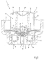
- a pressure regulator for a fuel supply system (not shown) is shown overall by 1; the regulator 1 comprises a container 2 of substantially cylindrical shape and is housed in a chamber 3 connected via a lower annular duct 4 to a fuel supply duct (not shown).
- the container 2 is cylindrically symmetrical about an axis 5 and is formed by joining a cup-shaped upper portion 6 and a cup-shaped lower portion 7; the lower portion 7 has a series of through holes 8 adapted to keep the duct 4 permanently in communication with a lower portion 9a of an inner chamber 9 of the container 2.
- the chamber 9 houses a regulation valve 10 which is normally closed and is adapted to bring the lower portion 9a of the chamber 9 into communication with a cylindrical exhaust duct 11 coaxial to the axis 5 and communicating with a fuel tank (not shown).
- the pressurised fuel is supplied via the supply duct (not shown) and is therefore also supplied to the duct 4 and to the lower portion 9a of the chamber 9.
- the valve 10 opens causing part of the fuel to flow along the duct 11 in order to achieve a situation of equilibrium in which the fuel pressure remains constant at a predetermined value.
- the valve 10 closes.
- elastomer rings 12 are interposed according to known methods between the container 2 and the chamber 3.
- the valve 10 comprises a fixed valve seat 13 obtained directly on the lower portion 7 and a valve body 14 moving in a control direction 15 parallel to the axis 5 between a closed position (shown in Figs. 1 and 2) in which the body 14 engages the seat 13 in a fluid-tight manner and an open position (not shown) in which the body 14 is raised with respect to the seat 13 thereby bringing the duct 11 into communication with the lower portion 9a of the chamber 9.
- the valve body 14 is pressed against the seat 13 by a main spring 16 at a predetermined force (generally between 60 and 19b N); the main spring 16 is disposed coaxially to the axis 5 between a respective housing 17 obtained on the upper portion of the body 14 and an upper wall of the chamber 9.
- the upper wall of the chamber 9 has a deformation 18 adapted to maintain an upper portion of the main spring 16 in a position coaxial to the axis 5.
- the chamber 9 is divided into two portions which are isolated from one another, i.e. a lower portion 9a and an upper portion 9b, by an impermeable and elastically deformable diaphragm 21 which has an annular shape and is connected in a fluid-tight manner externally to the lateral wall of the chamber 9 and internally to the valve body 14.
- the lower portion 9a is, in operation, filled with fuel and houses the valve seat 13, while the upper portion 9b houses the main spring 16, is free from pressurised fuel and is connected to atmosphere (at atmospheric pressure) via a through hole 22.
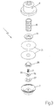
- the diaphragm 21 is connected to the container 2 at the zone of connection of the portions 6 and 7 of this container 2; as shown in Fig. 3, the diaphragm 21 is formed by joining two annular members.
- the thrust force of the main spring 16 is countered by the force exerted by the. fuel pressure on the portion of the diaphragm 21 disposed in contact with the fuel and by the fuel pressure on part of the lower surface of the body 14.
- the thrust exerted by the main spring 16 is therefore selected on the basis of the area of the diaphragm 21 and the body 14 disposed in contact with the fuel and on the basis of the predetermined pressure value at which the valve 10 is to act.
- the valve seat 13 comprises a central frustoconical hole 23 which is coaxial with the axis 5 and communicates with the duct 11; the hole 23 is bounded by a plane, annular metal surface 24.
- the body 14 comprises a support member 25, which is formed by joining two members 26 and 27 of stamped sheet superimposed on one another and partially folded over one another. According to a different embodiment which is not shown, the walls of the hole 23 have a parabolic or hyperbolic course.
- a lower portion of the support member 25 has a plane, annular metal surface 28 which is disposed in parallel with and facing the surface 24 of the seat 13 and is adapted to engage this surface 24 when the valve body 14 is disposed in the above-mentioned closed position (shown in Figs. 1 and 2).
- the support member 25 comprises an inner chamber 29 which is open at the bottom, which houses an elastomer shutter 30 which is adapted to engage the hole 23 of the valve seat 13 in a fluid-tight manner.
- the shutter 30 has a substantially hemispherical shape and engages an inner portion of the hole 23.
- the shutter 30 has a disc shape and engages an outer portion of the hole 23.
- the hemispherical shape of the shutter 30 is preferable, as it is self-centring with respect to the frustoconical hole 23 and the degree of sealing is substantially unaffected by small variations of the inclination of the shutter 30 with respect to the axis 5.
- the shutter 30 is mounted inside the chamber 29 so that it can move in the control direction 15 against the action of a secondary spring 31; in particular, an upper portion of the shutter 30 comprises a metal ring 32, which is substantially free to move within the chamber 29 and is secured to the secondary spring 31 which is in turn secured on opposite sides to an inner upper wall of the chamber 29. In this way, the shutter 30 may be displaced in a plane perpendicular to the control direction 16 in order to centre itself with respect to the hole 23.
- the ring 32 engages an inner lower surface of the chamber 29, limiting the downward stroke of the shutter 30 under the thrust of the secondary spring 31.
- the main spring 16 presses on the support member 25 with a relatively high force (61-19 bN); as a result of this thrust force, the support member 25 is displaced towards the seat 13 until the surface 24 of the valve seat 13 and the corresponding surface 28 of the member 25 are in reciprocal contact.
- the shutter 30 engages the hole 23 in a fluid-tight manner under the relatively contained thrust (8-15 N) of the secondary spring 31 and under the thrust of the hydraulic pressure of the fuel.
- the elastomer shutter 30 has to withstand the thrust of the secondary spring 31, which thrust is relatively contained and is calibrated in order to ensure a high level of fluid-tightness without, however, excessively stressing the shutter 30.
- the thrust of the main spring 16 which is relatively high in order to counter the fuel pressure, is borne wholly by the metal surfaces 24 and 28. In this way, the shutter 30 ensures a completely hermetic closure of the valve seat 13 even at relatively high fuel pressure values and, at the same time, is not mechanically stressed, thereby ensuring a relatively long service life.
- any dimensional variations (whether positive or negative) of the shutter 30 as a result of the chemical action of the fuel do not entail any kind of drawback, as the secondary spring 31 makes it possible to recover the play resulting from such dimensional variations of the shutter 30 without any problem.
- the ratio between the operating thrust of the secondary spring 31 and the operating thrust of the main spring 16 is normally lower than 0.15.
- the lower portion 7 of the container 2 is made in one piece from stamped sheet and comprises the valve seat 13.
- This embodiment is clearly different from the prior art, according to which the valve seat is formed in an upper portion of the duct 11, as it enables a reduction of the assembly costs of the regulator 1 by making it possible to connect the duct 11 to the portion 7 only in a final stage of construction of this regulator 1.
- the fact that the valve seat 13 is provided directly on the lower portion 7 is enabled by the use of a rubber shutter 30 which does not require particular processing (such as, for instance, lapping) of the valve seat 13.
- the support member 25 of the valve body 14 is entirely produced by joining several components of stamped sheet, in particular the components 26 and 27 described above, and an annular component 33 comprising the housing 17 for the main spring 16.
- This embodiment is clearly different from the prior art, according to which the support member 25 is produced by lathe processing of a single metal component, since it makes it possible drastically to reduce the production costs of this member 25.
Landscapes
- Engineering & Computer Science (AREA)
- Physics & Mathematics (AREA)
- Chemical & Material Sciences (AREA)
- Combustion & Propulsion (AREA)
- Mechanical Engineering (AREA)
- General Engineering & Computer Science (AREA)
- Fluid Mechanics (AREA)
- General Physics & Mathematics (AREA)
- Automation & Control Theory (AREA)
- Fuel-Injection Apparatus (AREA)
- Control Of Fluid Pressure (AREA)
- Safety Valves (AREA)
Applications Claiming Priority (2)
| Application Number | Priority Date | Filing Date | Title |
|---|---|---|---|
| ITBO990652 | 1999-11-30 | ||
| IT1999BO000652A IT1311407B1 (it) | 1999-11-30 | 1999-11-30 | Regolatore di pressione per impianti di alimentazione carburante . |
Publications (1)
| Publication Number | Publication Date |
|---|---|
| EP1106820A1 true EP1106820A1 (de) | 2001-06-13 |
Family
ID=11344381
Family Applications (1)
| Application Number | Title | Priority Date | Filing Date |
|---|---|---|---|
| EP00125596A Withdrawn EP1106820A1 (de) | 1999-11-30 | 2000-11-22 | Druckregler für Kraftstofffördersysteme |
Country Status (3)
| Country | Link |
|---|---|
| EP (1) | EP1106820A1 (de) |
| BR (1) | BR0006747A (de) |
| IT (1) | IT1311407B1 (de) |
Cited By (1)
| Publication number | Priority date | Publication date | Assignee | Title |
|---|---|---|---|---|
| FR2844834A1 (fr) * | 2002-09-20 | 2004-03-26 | Siemens Vdo Automotive Corp | Regulation de la pression d'une alimentation en carburant |
Citations (4)
| Publication number | Priority date | Publication date | Assignee | Title |
|---|---|---|---|---|
| US4130267A (en) * | 1974-09-20 | 1978-12-19 | Aisin Seiki Kabushiki Kaisha | Pneumatic control system and pressure responsive valve assembly therefor |
| US4790343A (en) * | 1986-03-31 | 1988-12-13 | Aisin Seiki Kabushiki Kaisha | Pressure regulator |
| US5265644A (en) * | 1992-06-02 | 1993-11-30 | Walbro Corporation | Fuel pressure regulator |
| DE19635438A1 (de) * | 1996-08-31 | 1998-03-05 | Bosch Gmbh Robert | Druckreglerventil |
-
1999
- 1999-11-30 IT IT1999BO000652A patent/IT1311407B1/it active
-
2000
- 2000-11-22 EP EP00125596A patent/EP1106820A1/de not_active Withdrawn
- 2000-11-28 BR BR0006747-4A patent/BR0006747A/pt not_active IP Right Cessation
Patent Citations (4)
| Publication number | Priority date | Publication date | Assignee | Title |
|---|---|---|---|---|
| US4130267A (en) * | 1974-09-20 | 1978-12-19 | Aisin Seiki Kabushiki Kaisha | Pneumatic control system and pressure responsive valve assembly therefor |
| US4790343A (en) * | 1986-03-31 | 1988-12-13 | Aisin Seiki Kabushiki Kaisha | Pressure regulator |
| US5265644A (en) * | 1992-06-02 | 1993-11-30 | Walbro Corporation | Fuel pressure regulator |
| DE19635438A1 (de) * | 1996-08-31 | 1998-03-05 | Bosch Gmbh Robert | Druckreglerventil |
Cited By (1)
| Publication number | Priority date | Publication date | Assignee | Title |
|---|---|---|---|---|
| FR2844834A1 (fr) * | 2002-09-20 | 2004-03-26 | Siemens Vdo Automotive Corp | Regulation de la pression d'une alimentation en carburant |
Also Published As
| Publication number | Publication date |
|---|---|
| ITBO990652A0 (it) | 1999-11-30 |
| IT1311407B1 (it) | 2002-03-12 |
| BR0006747A (pt) | 2001-12-04 |
| ITBO990652A1 (it) | 2001-05-30 |
Similar Documents
| Publication | Publication Date | Title |
|---|---|---|
| KR100295547B1 (ko) | 감압밸브 | |
| US4646700A (en) | Pressure regulator for liquid fuel system | |
| US2057150A (en) | Two-stage pressure regulator | |
| US11792944B2 (en) | Valve for pressure compensation and/or for emergency venting of a container, in particular of a container of a battery of an electric vehicle, as well as container with such a valve | |
| US7143956B2 (en) | Suck back valve | |
| EP0585810A1 (de) | Druckregler | |
| US4768542A (en) | Drain valve | |
| US4776562A (en) | Dual piston pneumatically operated valve | |
| US8186372B2 (en) | Fuel shut-off valve | |
| KR101020711B1 (ko) | 정류량 밸브 | |
| US3544065A (en) | Resilient annular valve seat with coaxial rigid annular member | |
| US4838305A (en) | Pressure differential valve | |
| EP1106820A1 (de) | Druckregler für Kraftstofffördersysteme | |
| CA2209632C (en) | Self-aligning valve disc assembly | |
| US6382183B1 (en) | Fuel system pressure regulator | |
| US6886590B2 (en) | Seal assembly for fuel pressure regulator | |
| GB2298026A (en) | Pressure reducing valve | |
| US5660204A (en) | Tank blanketing valve | |
| US3407841A (en) | Fluid pressure regulators | |
| US4284391A (en) | Crashworthy fuel pump improvement | |
| US4164955A (en) | Liquid level control valve | |
| JP2011237039A (ja) | ダイアフラム弁 | |
| JP2018112226A (ja) | 逃がし弁 | |
| US3681832A (en) | Method of making a poppet valve construction | |
| JPS595644Y2 (ja) | 作動液リザ−バ |
Legal Events
| Date | Code | Title | Description |
|---|---|---|---|
| PUAI | Public reference made under article 153(3) epc to a published international application that has entered the european phase |
Free format text: ORIGINAL CODE: 0009012 |
|
| AK | Designated contracting states |
Kind code of ref document: A1 Designated state(s): DE ES FR GB SE |
|
| AX | Request for extension of the european patent |
Free format text: AL;LT;LV;MK;RO;SI |
|
| 17P | Request for examination filed |
Effective date: 20010411 |
|
| AKX | Designation fees paid |
Free format text: DE ES FR GB SE |
|
| STAA | Information on the status of an ep patent application or granted ep patent |
Free format text: STATUS: THE APPLICATION IS DEEMED TO BE WITHDRAWN |
|
| 18D | Application deemed to be withdrawn |
Effective date: 20060614 |