EP1106306B1 - Setzgerät für Spreiz-Maueranker - Google Patents
Setzgerät für Spreiz-Maueranker Download PDFInfo
- Publication number
- EP1106306B1 EP1106306B1 EP00309622A EP00309622A EP1106306B1 EP 1106306 B1 EP1106306 B1 EP 1106306B1 EP 00309622 A EP00309622 A EP 00309622A EP 00309622 A EP00309622 A EP 00309622A EP 1106306 B1 EP1106306 B1 EP 1106306B1
- Authority
- EP
- European Patent Office
- Prior art keywords
- gripper
- axis
- slider
- lever
- plane
- Prior art date
- Legal status (The legal status is an assumption and is not a legal conclusion. Google has not performed a legal analysis and makes no representation as to the accuracy of the status listed.)
- Expired - Lifetime
Links
Images



Classifications
-
- B—PERFORMING OPERATIONS; TRANSPORTING
- B25—HAND TOOLS; PORTABLE POWER-DRIVEN TOOLS; MANIPULATORS
- B25B—TOOLS OR BENCH DEVICES NOT OTHERWISE PROVIDED FOR, FOR FASTENING, CONNECTING, DISENGAGING, OR HOLDING
- B25B27/00—Hand tools, specially adapted for fitting together or separating parts or objects whether or not involving some deformation, not otherwise provided for
- B25B27/0007—Tools for fixing internally screw-threaded tubular fasteners
-
- B—PERFORMING OPERATIONS; TRANSPORTING
- B21—MECHANICAL METAL-WORKING WITHOUT ESSENTIALLY REMOVING MATERIAL; PUNCHING METAL
- B21J—FORGING; HAMMERING; PRESSING METAL; RIVETING; FORGE FURNACES
- B21J15/00—Riveting
- B21J15/38—Accessories for use in connection with riveting, e.g. pliers for upsetting; Hand tools for riveting
- B21J15/386—Pliers for riveting
-
- Y—GENERAL TAGGING OF NEW TECHNOLOGICAL DEVELOPMENTS; GENERAL TAGGING OF CROSS-SECTIONAL TECHNOLOGIES SPANNING OVER SEVERAL SECTIONS OF THE IPC; TECHNICAL SUBJECTS COVERED BY FORMER USPC CROSS-REFERENCE ART COLLECTIONS [XRACs] AND DIGESTS
- Y10—TECHNICAL SUBJECTS COVERED BY FORMER USPC
- Y10T—TECHNICAL SUBJECTS COVERED BY FORMER US CLASSIFICATION
- Y10T29/00—Metal working
- Y10T29/53—Means to assemble or disassemble
- Y10T29/53709—Overedge assembling means
- Y10T29/53717—Annular work
- Y10T29/53726—Annular work with second workpiece inside annular work one workpiece moved to shape the other
- Y10T29/5373—Annular work with second workpiece inside annular work one workpiece moved to shape the other comprising driver for snap-off-mandrel fastener; e.g., Pop [TM] riveter
-
- Y—GENERAL TAGGING OF NEW TECHNOLOGICAL DEVELOPMENTS; GENERAL TAGGING OF CROSS-SECTIONAL TECHNOLOGIES SPANNING OVER SEVERAL SECTIONS OF THE IPC; TECHNICAL SUBJECTS COVERED BY FORMER USPC CROSS-REFERENCE ART COLLECTIONS [XRACs] AND DIGESTS
- Y10—TECHNICAL SUBJECTS COVERED BY FORMER USPC
- Y10T—TECHNICAL SUBJECTS COVERED BY FORMER US CLASSIFICATION
- Y10T29/00—Metal working
- Y10T29/53—Means to assemble or disassemble
- Y10T29/53709—Overedge assembling means
- Y10T29/53717—Annular work
- Y10T29/53726—Annular work with second workpiece inside annular work one workpiece moved to shape the other
- Y10T29/5373—Annular work with second workpiece inside annular work one workpiece moved to shape the other comprising driver for snap-off-mandrel fastener; e.g., Pop [TM] riveter
- Y10T29/53757—Annular work with second workpiece inside annular work one workpiece moved to shape the other comprising driver for snap-off-mandrel fastener; e.g., Pop [TM] riveter having allochiral actuating handles
Definitions
- the present invention relates to a setting gripper for an anchor device as per preamble of claim 1, as such disclosed in US-A-4 625 538.
- GB-A-2 289 006 discloses a gripper comprising :
- anchoring devices of the type concerned we can mention expanding metal plugs of which an embodiment is described in French patent 2 546 989 and sold under the registered trade mark "Molly" and which is set when a screw is engaged co-axially therein by pulling on the head of the screw while holding the plug by a flange integral therewith and forming a head for supporting it on a hollow support in a hole of which setting is effected.
- Certain rivets which are set blind can also be mentioned and, in general, with respect to the present invention, any anchoring device which is set blind by co-axial spreading apart of heads of components which are themselves co-axial whatever the configuration of these heads and the nature of these components will be considered as similar to expanding metal plugs.
- This British patent application describes a gripper in which the lever is supported on the gripper body via a pivot which is stationary relative to each, in other words only allows a relative rotational movement round the corresponding axis whereas the lever is supported on the slider between this axis and the handles via a cam of the lever and an opposing part of the slider under conditions which are such that, as the handles are brought together by clenching of the fist, the zone of mutual support for the lever and the slider gradually moves away from the axis of articulation of the lever on the gripper body.
- the minimum value of the lever arm between the zone of mutual contact between the lever and the slider and the axis of articulation of the lever on the gripper body allows the user to apply to the heads a maximum force of spreading apart by means of a reasonable force applied to the handles in the sense of mutual bringing together.
- This lever arm then increases progressively as the handles are brought together, in other words as the two heads are spread apart, which means that less force is required for this purpose.
- the present invention provides a gripper as per claim 1.
- a gripper according to the invention therefore retains the advantageous characteristic of increasing the lever arm as the handles are brought together, in other words as setting proceeds, in a manner which is particularly well adapted to the case of the setting of expanding metal plugs.
- This progression is obviously discontinuous, whereas it is continuous in the case of a gripper according to the teaching of the aforementioned British patent application owing to the cooperation between the lever cam and the counterpart on the slider, but experience has shown that such a discontinuity is quite acceptable if there is an adequate number of examples of cooperating zones of the piston body and the lever, and their distribution in the sense of moving away from the cooperating zones of the slider and the lever is selected appropriately.
- three examples of the cooperating zones of the gripper body and of the lever are currently considered sufficient, but a different number could be selected within the scope of the present invention.
- the range of variation of the lever arm may be much greater as it can be distributed over the entire size of the lever between its zone cooperating with the slider and the handle of the lever and in a corresponding manner on the gripper body whereas the size of the cam and of its counterpart on the slider, perpendicularly to the direction of sliding thereof, in the case of a gripper according to the aforementioned British patent application is necessarily much more limited, in particular on account of the design of the slider and its cooperation with the gripper body.
- the position of the cooperating zones of the slider and of the lever perpendicularly to the direction of translation of the slider varies far less in the case of a gripper according to the invention than in the case of a gripper according to the teaching of the aforementioned British patent application, so it is possible to keep them sufficiently close to the axis of the two components of the anchor device for the tendency of the slider to rock relative to the gripper body to remain particularly moderate, in fact virtually negligible, so the friction occurring between the slider and the gripper body is much lower than in the case of a gripper according to the teaching of the aforementioned British patent application, and this further increases the performance of the gripper according to the present invention as defined herein before.
- the means for holding a zone of the lever relative to the body of the gripper and/or to the slider can be located in cooperating zones of the lever and of the slider, which are mounted so as to rotate relative to one another round an axis which is stationary relative to the lever and relative to the slider which enables this axis to be passed in the immediate vicinity of the common axis of the two components of the anchor device to be set, in other words, enables the force of the lever to be applied to the slider virtually in the axis of these parts, under particularly favourable mechanical conditions.
- the holding means are located in one of said zones of the gripper body and of the slider and in the corresponding zone of the lever and comprise means for mutual immobilisation against any relative translation at least approximately perpendicularly to said direction, whereas the others of said zones of the gripper body and of the slider and the respectively corresponding zones of the lever allow a relative movement approximately perpendicularly to said direction.
- said holding means comprise, in the zone of said zones of the gripper body closest to said zone of the slider and in the corresponding zone of the lever, means for guidance in relative translation at least approximately in said direction. Therefore, if the rotation of the lever relative to the gripper body is effected by their cooperating zones closest to the cooperating zones of the lever and the slider, in other words, if the forces between the lever and the gripper body are greatest, their relative movement is exclusively a rotational movement and the losses by friction in this region are reduced to a minimum.
- the other zone, of which there is at least one, of said zones of the gripper body or the corresponding zone of the lever comprises a convex surface in the form of part of a cylinder of revolution round the corresponding axis, for the support of this zone of the lever on this zone of the gripper body in the direction opposed to said direction, and this is a particularly simple method of allowing the necessary rotation, the clearance required to substitute one axis for another during the pivoting of the lever relative to the gripper body and a possibility of relative translation perpendicularly to the direction of translation of the slider relative to the gripper body, in their cooperating zones.
- zone of the slider and said corresponding zone of the lever are preferably designed in such a way that they comprise means for guidance in relative translation at least approximately perpendicularly to said direction, in order to maintain the possibility of relative deflection in this direction also at this level.
- the cooperating zones of the slider and of the lever comprise means for guidance in relative translation at least approximately perpendicularly to the direction of translation of the slider relative to the gripper body
- elastic means for returning the handles in the direction of the spreading apart, in other words toward their relative rest position also ensure that the slider and the gripper body are returned to their relative rest position.
- the configuration of the gripper according to the invention should obviously be adapted to the configuration of the anchor devices which it is intended to set, this being the case, in particular, with the configuration of its jaws.
- the two jaws advantageously have, in a same plane including said direction and constituting a mean plane of symmetry common to the slider and to the gripper body, a respective notch for engagement on one of the two components which comprises the shank, the two notches being open on either side in said direction and in a direction perpendicular thereto to allow the shank to pass between the two heads.
- the two jaws are preferably interchangeable, and this can be ensured by the inter-changeability of the entire slider with regard to its jaw and by the fact that the gripper body comprises an interchangeable nose constituting the corresponding jaw.
- the cooperation between at least one of the jaws and the corresponding component of the anchor device is achieved by means of an appropriately configured adaptor attached integrally but removably, for example by magnetic fixing, to this jaw.
- US 4625538 describes a plug grip having first and second arms pivotally mounted together to support a flat shoe member and a stirrup member for raising the screw of an expansion plug.
- the plug grip firstly exerts a large force on the expansion plug as the handles are brought together, and then exerts a smaller force on expansion plug after the leg portion of the plug is deformed.
- the torque exerted when pivoting about the second pivot point is less than that exerted when pivoting about the first pivot point.
- a setting gripper for an anchor device of the type comprising two co-axial components of which each has a head and of which the heads are spread apart along an axis during setting, said gripper comprising:
- a metal anchor plug of this type comprises a body 2 which is symmetrical about a longitudinal axis 3 and is essentially formed by four longitudinal branches 5 uniformly distributed angularly round the axis 3 and joining two longitudinally extreme transverse rings 6, 7 together integrally by producing a single part.
- the ring 6 integrally holds a coaxial nut 4 whereas the ring 7 carries integrally, preferably removably, a head 8 in the form of a transverse annular flange surrounding the ring 7 in the direction away from the axis 3.
- the branches 5 have an elbow so as to have a shape which is generally curved in the direction away from the axis 3.
- a plug 1 of this type is intended to be anchored coaxially in a hole 9 in a wall 10 which it passes right through along its axis 3 and to anchor, with respect to this wall 10, a screw 11 of which the shank 12 is screwed coaxially in the nut 4 held by the ring 6 and which has a head 13 longitudinally facing the head 8 of the plug 1.
- the head 13 is a flat head which is connected to the shank 12 by a plane annular shoulder perpendicular to the axis 3 in the example illustrated in Fig.
- a gripper according to the invention 16 can also be used for setting plugs 1 equipped with a countersunk screw of which the aforementioned shoulder has the form of a truncated cone of revolution about the axis 3 rather than being plane and perpendicular thereto.
- a plug 1 of this type is set in a wall 10 blind, in other words exclusively from one 14 of two mutually parallel faces 14, 15 thereof in a manner which will now be described.
- the wall 10 is perforated from its face 14 and along an axis perpendicular to this face 14 with a hole 9 of appropriate diameter, then the plug 1 is engaged through the ring 6 coaxially in this hole 9 until the head 8 of the plug 1 rests flat against the face 14 round the hole 9.
- this operation is carried out when the plug 1 is already equipped with the screw 11, screwed by its shank 12 into the nut 4 held by the ring 6 and having its head 13 longitudinally opposite to the head 8 of the plug 1; if this is not the case, the screw 11 is engaged with the plug 1 while taking care to keep the head 13 at a slight longitudinal distance from the head 8 to allow insertion of a zone of a setting gripper, in particular the gripper according to the invention 16, under conditions which will be described in detail hereinafter.
- the head 13 is then subjected to traction by the gripper 16 along the axis 3 in the direction 17 away from the head 8 while keeping the head 8 applied flat against the face 14 round the hole 9, obviously without allowing the screw to turn round the axis 3 relative to the plug 1.
- the branches 5 are deflected away from the axis 3 by bending of each branch 5, on the one hand, relative to the two rings 6 and 7 and, on the other hand, in a longitudinally central zone between them, this deflection being continued until the half of the branches 5 closest to the ring 7 is applied flat to the face 15 of the wall 10 round the hole 9.
- the plug 1 is then held integrally by the partition 10, which it grips between the head 8 and the branches 5 deflected in this way, whereas the ring 7 matches the interior of the hole 9 without clearance or virtually without clearance.
- the screw 11 can then be unscrewed, and the nut 4 held integrally by the ring 6 of the plug 1 can be used to anchor to it, and by it to the wall 10, by means of the screw 11 or by means of another screw of the same diameter, any article which is to be anchored to the wall 10.
- articles of any type can be anchored to the wall 10 with a resistance to traction along the axis 3 and/or to shearing relative thereto which is generally much greater than that obtained with other types of plug.
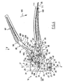
- the gripper 16 comprises three main components which are moveable relative to one another and are respectively symmetrical about a plane 18 which, during the setting of a plug 1 includes the axis 3, namely a rigid gripper body 19 which constitutes the most solid component and carries the two other main components, a rigid lever 20 articulated about a gripper body 19 in a manner characteristic of the present invention and giving it its symmetry about the plane 18, and a rigid slider 21 which is moveable in translation inside the gripper body 19 under the influence of the pivoting of the lever 20 relative thereto in a predetermined longitudinal direction which is that of the axis 3 common to the plug 1 and the screw 11 during the setting of the plug 1, to the extent that reference numeral 3 will be used to designate both this direction and an axis which is common to the respective parts of the slider 21 and the gripper body 19 as well as the screw 11 and the plug 1.
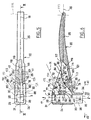
- the gripper body 19 will now be described more particularly with reference to Fig. 3 to 6.
- the part 22 defines, round the axis 3, considered in this description as stationary relative to this part 22 although its position can vary slightly in the plane 18 but without a change of orientation depending on the diameters of the shank 12 of the screw 11, a housing 24 which is longitudinal, in other words elongated along the axis 3, and furthermore defines a handle 25 which is transverse, in other words elongated along a mean axis 35 perpendicular to the axis 3 and projecting from this axis 3 on one side relative to the housing 24.
- the handle 25 has longitudinal dimensions which are much smaller than those of the housing 24 to which it is connected by a transition zone 26 of which the longitudinal dimension increases progressively from the handle 25 toward the housing 24, in other words in the direction of coming toward the axis 3, but without attaining the longitudinal dimension of the housing 24 at its connection thereto.
- the housing 24, the handle 25 and the transition zone 26 are respectively symmetrical about the plane 18 in which the mean axis 35 of the handle 25, in particular, is situated; perpendicularly to this plane 18, the handle 25 has dimensions smaller than those of the housing 24 whereas the transition zone 26 has dimensions intermediate between those of the handle 25 and those of the housing 24.
- the housing 24 is hollow and, more precisely, has a general tubular shape surrounding the axis 3 and open in both directions thereof, namely in a direction corresponding to the direction 17 during setting and which has been given the same reference numeral 17, and in the opposite direction 27, these directions ascending and descending respectively when referring to the example of setting described with reference to Fig. 1 and 2.
- the housing 24 has a constant rectangular internal cross-section defined by two plane faces 28 which are themselves rectangular and identical to one another, parallel to the plane 18 and mutually symmetrical about the plane 18, and by two plane faces 29, 30 which are also rectangular and are respectively symmetrical about the plane 18 and parallel to the axis 3, the two faces 29 and 30 joining together the faces 28 respectively on the side of the axis 3 remote from the handle 25 and on the side with this handle 25.
- the four faces 28, 29, 30 end in the same region by respective connection to a transverse annular edge 31 of the housing 24.
- the two faces 28 are extended to a respective edge 32 of the housing 24, the two edges 32 being located in a same non-designated geometric plane perpendicular to the axis 3, whereas the face 29 continues to an edge 33 of the housing 24, which edge 33 is also located in a non-designated geometric plane perpendicular to the axis 3 but broadly set back from the geometric plane of the edges 32, and the face 33 continues to an edge 34 of the housing 24, which edge 34 is located in a geometric plane, not shown, perpendicular to the axis 3 and located between the respective geometric planes of the edges 32 and of the edge 33, in other words set back in the direction 17 from the common geometric plane of the edges 32 but remaining closer to this plane than that of the edge 33.
- the housing 24 designed in this way internally receives the slider 21 and ensures the guidance in translation thereof along the axis 3 in directions 17 and 27 relative to the part 22 and more generally relative to the gripper body 19, while preventing any other relative movement.
- the translation of the slider 21 inside the housing 24 is limited by the nose 23 which, as shown in particular in Fig. 1 to 4, is configured and attached to the housing 24 so as partially to block it in the direction 27.
- the nose 23 which is rigid and produced, for example, from drop-forged sheet metal or again from a metal profile is symmetrical about the plane 18 and has a U-shaped section when viewed in section through a plane perpendicular to the direction 35 of the handle 25 when it is fixed to the part 22 so as to constitute the gripper body 19.
- the nose comprises, in a single part, a flat core 36 which is applied flat, by a plane face 47 against the two edges 32 of the housing 24 and thus closes the housing 24 in the direction 27 and two wings 37 which are also flat and are parallel to the plane 18 about which they are mutually symmetrical, each of these wings 37 matching a respective non-designated rebate made on the exterior of the housing 24 in the immediate vicinity of a respective edge 32 to ensure that the nose 23 fits on the housing 24 in the direction 17.
- Each wing 37 is held thereon by a respective screw 38 engaged along an axis 39 perpendicular to the plane 18 in a corresponding non-designated hole in the wing 37 and screwed in a corresponding hole 40 in the housing 24, obviously without projecting to the interior thereof relative to the corresponding face 28.
- the bearing of the core 36 against the edges 32 of the housing 24, the fitting of the wings 37 thereon and the screwing by the screws 38 ensure that the nose 23 is fixed relative to the part 22 without affecting the possibility of removal and replacement of the nose 23.
- edge 43 turned in the direction 41 is continuous but the edge 44 turned in the direction 42 has a discontinuity in the region of the core 36 in the form of a notch 45 traversing the core 36 longitudinally on either side in a manner located symmetrically about the plane 18 while surrounding the axis 3 but without attaining the edge 43.
- the notch 45 is delimited by two flanks 46 which are symmetrical to one another about the plane 18 and of which each one is connected to the edge 44 in the direction 42, the two flanks 46 being joined together in the direction 41 and of which each one is connected respectively in the direction 17 and in the direction 27 to the plane face 47 of the core 36 turned in the direction 17 and resting flat against the edges 32 of the housing 24, and to the plane face 48 of the core 36 parallel to the face 47 and perpendicular, like it, to the axis 3 and turned away from the face 47, in other words toward the exterior of the housing 24 in the direction 27.
- Each of the flanks 46 has, at its connection to the edge 44, a plane zone 149 which is parallel to the plane 18 and extends in the direction 41 from the edge 44 over about half of the distance separating it from the axis 3.
- each zone 149 is connected to a zone 150 of the flank 46 which is also plane but oblique relative to the plane 18 so as to come toward the plane 18 in the direction 41 but without intersecting it, to a distance from the edge 44, in direction 41, which is slightly greater than the distance separating the axis 3 from this edge 44.
- the zones 150 of the two flanks 46 are joined together by a concave bottom zone 151 in the form of a portion of a cylinder of revolution about the axis 3, with a diameter corresponding substantially to the smallest diameter of the shank 12 of the screw 11 corresponding to a plug 1 capable of being set by the gripper according to the invention.
- the mutual spacing between the two zones 149 perpendicularly to the plane 18 is, for its part, substantially equal to or slightly greater than the greatest diameter of the shank 12 of the screw 11 provided in a plug 1 capable of being set by the gripper according to the invention.
- the nose 23 thus constitutes, on the gripper body 19, with its core 36, one of the jaws of the gripper 16, of which the other jaw is constituted by the slider 21 which will now be described.
- the slider 21, like the housing 24, has a shape which is elongated longitudinally, in other words along the axis 3, but its dimensions along this axis 3 are smaller than the internal dimension of the housing 24 measured between the edge 31 and the edges 32.
- It may be produced from drop-forged sheet metal or from a metal profile and, when viewed through a sectional plane perpendicular to the axis 35, has a C-shaped section symmetrical about the plane 18.
- the slider 21 comprises, in a single part, a flat core 49 perpendicular to the axis 3 and to the plane 18 about which it is symmetrical, constituting, for the gripper 16, a jaw cooperating with the jaw formed by the core 36 of the nose 23 of the gripper body 19, two wings 50 which are also flat, are elongated parallel to the axis 3, are identical to one another and symmetrical to one another about the plane 18 to which they are parallel, and two flat flanges 51 which the wings 50 connect to the core 49 and which are directed toward one another, parallel to the core 49 and perpendicular to the plane 18 about which they are symmetrical to one another, without reaching this plane 18 toward which they have a respective plane edge 52 parallel to this plane 18 along which these two edges 52 leave a clear slot 53 between themselves.
- the core 49, the two wings 50 and the two flanges 51 are delimited respectively in the direction 41 and in the direction 42 by a plane edge 54, 55 which is perpendicular to the plane 18 and parallel to the axis 3 whereas, in the direction away from the plane 18, the wings 50 are delimited by a respective plane rectangular face 56.
- the distance mutually separating the edges 54 and 55 is substantially equal to the distance mutually separating the internal faces 29 and 30 of the housing 24, and the distance mutually separating the faces 56 of the wings 50 is substantially equal to the distance mutually separating the internal faces 28 of the housing 24 so that a sliding contact for guiding the slider 21 during sliding parallel to the axis 3 inside the housing 24 is established between the edges 54 and 55 and the faces 30 and 29, on the one hand, and between the faces 56 and the faces 28, on the other hand.
- the wings 50 parallel to their faces 56, have faces 57 which are also plane, are parallel to the plane 18 and symmetrical to one another about the plane 18, these faces 56 delimiting between themselves a space 58 inside the slider 21 which is found to be completely open in the direction 42, similarly to the housing 24 between the edge 33 and the common geometric plane of the edges 32.
- this space is closed on either side of the slot 53 by plane faces 59 of the two flanges 51, which plane faces 59 are disposed in the same geometric plane perpendicular to the axis 3 whereas, in the direction 27, the space 58 is closed by a plane face 60 perpendicular to the axis 3, of the core 49, which is otherwise delimited, in the direction 27, by a further plane face 61 perpendicular to the axis 3 and placed directly opposite the face 47 of the core 36 of the nose 23 along the axis 3.
- the core 49 is attached by its face 61 to the face 47 of the core 36 but can move away from it in the direction 17 by sliding of the slider 21 inside the housing 24 and return to this rest position by sliding of the slider 21 conversely in the direction 27 inside the housing 24.
- the core 49 of the slider 21 is recessed by a notch 62 which is identical in every way to the notch 45 in the core 36 of the nose 23, the two notches 62 and 45 being exactly superimposed along the axis 3 in the rest position of the slider 21 relative to the housing 24.
- the notch 62 is delimited on either side of the plane 18 by a flank 63 which is identical in all ways to the flank 46 of the notch 45 located on the same side of the plane 18, and each flank 63 longitudinally extends a respective flank 46.
- the faces 57 of the wings 50 are mutually spaced perpendicularly to the plane 18 by a distance at least equal to the greatest diameter of the head 13 of the screw 11 compatible with the range of plugs for which the gripper 16 is intended; furthermore, in the rest position of the slider 21 there remains between the face 60 of the core 49 of the slider 21 and the edge 33 of the housing 24 a space 134 which is open in the direction 42 and, parallel to the axis 3, has a dimension at least equal to the greatest thickness which the head 13 of the screw 11 can have along this axis, this head 13 corresponding to a plug 1 capable of being set by the gripper according to the invention.
- the core 36 of the nose 23 and the core 49 of the slider 21 can be inserted together in the direction 42 perpendicular to the axis 3 round the shank 12 of the screw 11 of which the head 13, for this purpose, is sufficiently far removed from the head 8 of the plug 1 to a position illustrated in Fig.
- the two cores 46 and 47 superimposed in this way constitute, for the gripper 16, two jaws capable of being spread from their rest position, during which movement the jaw constituted by the core 36 of the nose 23 holds the head 8 of the plug 1 whereas the jaw constituted by the core 49 of the slider 21 pulls the head of the screw 11 in the direction shown diagrammatically at 17 in Fig. 2, causing the anchoring of the plug as described herein before. It is then easy to release the two jaws of the assembly formed by the screw 11 and the plug 1 by a movement of the gripper 16 in the direction 41 relative to the screw 11, if necessary after having brought the slider 21 back to its rest position relative to the gripper body 19.
- the two wings 50 of the slider 21 have, recessed in the edge 54 closer to the flanges 51 than the core 49, two notches 64 which are symmetrical to one another about the plane 18 along a same mean plane 65 perpendicular to the axis 3.
- Each of these notches is delimited by an edge 66 opening in the two faces 56, 57 of the respective wing 50 and comprising, from the edge 54 to the vicinity of the axis 3 and on the same side of this axis 3 as the edge 54, two plane flanks 67, 68 which are parallel to the plane 65 and are symmetrical to one another about it and are turned in the direction 17 and in the direction 27 respectively.
- each edge 66 Remote from their connection to the edge 54, the flanks 67 and 68 of each edge 66 are joined together by a respective concave bottom 69 forming a half cylinder of revolution about an axis 70 perpendicular to the plane 18 and situated in the plane 65.
- the part 22 for its part comprises, in the transition zone 26 along mean axis 71 located in the plane 18 intersecting the axis 3 at the same point as the axis 35 and progressively moving away from it while forming an angle of about 30° therewith in the direction of moving away from the axis 3 on the same side of the axis 3 as the handle 25, in other words in the direction 41, a passage 72 opening on the one hand inside the housing 24 and, more specifically, in the face 30 thereof and, on the other hand, toward the exterior of the housing 24 in a plane face 73 perpendicular to the plane 18 generally turned in the direction 17 and delimiting the transition zone 26 between the housing 24 and the handle 25.
- this face 73 is connected to the edge 31 of the housing 24 toward the axis 3 and to the handle 25 in the direction moving away from the axis 3, while having obliqueness relative to the axis 35 which is almost the reverse of that of the axis 71.
- the passage 72 is delimited in the direction moving away from the plane 18 by two plane faces 74 parallel to this plane 18 and symmetrical to one another about it, which faces 74 join together the faces 30 and 73 and are mutually spaced perpendicularly to the plane 18 by a distance smaller than that mutually separating the interior faces 28 of the housing 24.
- the passage 72 is also delimited by two faces 75, 76 perpendicular to the plane 18 and respectively symmetrical about it.
- the face 75, parallel to the axis 71 and situated on the same side of it as the edge 31, is plane and parallel to the axis 71 and joins the faces 74 together perpendicularly to the plane 18 and the faces 30 and 73 parallel to the axis 71, the connection to the face 73 being obtained by means of an intersected plane 77 perpendicular to the plane 18 and parallel to the axis 3, producing, more precisely, the connection to the face 73 in the region of its connection to the edge 31.
- the face 76 located opposite the face 75 in a position approximately symmetrical to that of this face 75 about the axis 71, for its part, comprises a plurality of zones which follow one another parallel to the axis 71 from its connection to the internal face 30 of the housing 24 to its connection to the face 73, the face being defined in each of these zones by generatrices perpendicular to the plane 18 and joining the two faces 74 together from its connection to the face 30 up to its connection to the face 73.
- the face 76 comprises, in succession, in a direction defined by the axis 71:
- the zones 81 and 84 act as a bearing means for the lever 20 approximately in the direction 27 relative to the gripper body 19, with the possibility of relative rotation about the axis 82 and about the axis 85 respectively.
- the part 22 of the gripper body 19 has, at the connection between the transition zone 26 and the housing 24, two apertures 88 which open into the passage 72 via a respective face 74 thereof, perpendicularly to the plane 18, and which also open toward the exterior of the passage 72 via a respective external face 89 of the part 22 of the gripper body 19, the two faces 89 being turned in the direction away from the plane 18, parallel thereto and symmetrical to one another about it and defining, in the immediate vicinity of the edges 32, the aforementioned non-designated rebates for receiving the wings 37 of the nose 23.
- the apertures 88 which are symmetrical to one another about the plane 18 are oblong parallel to the axis 3 and respectively symmetrical about a same mean plane 90 perpendicular to the plane 18 and parallel to the axis 3.
- Each of them is delimited by an edge 91 comprising two plane flanks 92 which are symmetrical to one another about the plane 90 to which they are parallel and by two concave bottoms 93, 94 in the form of half cylinders of revolution about a respective axis 95, 96 perpendicular to the plane 18, these two bottoms 93 and 94 joining together the two flanks 92 while being turned respectively in the direction 17 so as to delimit the corresponding aperture 88 toward the face 76 of the passage 72 and, in the direction 27, to delimit the corresponding aperture 88 toward the face 75 of the passage 72, the dimension of each aperture 88 parallel to the axis 3 being smaller than the distance mutually separating the zone 78 from the face 76 and the face 75 parallel to this axis 3.
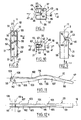
- the lever 20 is designed in a manner which will now be described, more particularly with reference to Fig. 3, 4, 11, 12 and in a rest position which it occupies relative to the gripper body 19 when the slider 21 itself occupies its rest position relative thereto; this rest position is illustrated in Fig. 3 and 4.
- the approximately rectilinear lever 20 has a mean axis 97 which, in this position, coincides with the axis 71 of the passage 72 in such a way that the lever 20, essentially projecting from the same side of the axis 3, relative to the housing 24 of the gripper body 19 as the handle 25, moves away from the handle 25 from an extreme zone 98 accommodated inside the slider 21 so as to cooperate therewith, to an extreme zone 99 forming a handle which a setting operator is able to grasp with the same hand as the handle 25 in an attempt to bring these two handles together by causing the lever 20 to rock relative to the gripper body 19 by clenching the hand.
- the end zone forming a handle 99 is obviously located outside the passage 72 opposite the handle 25 and offset from it in the direction 17.
- the comfort when gripping the handles 25 and 99 may be improved by integrally slipping thereon a respective sheath 100, 101 made of a suitable material, such as a synthetic rubber.
- the lever 20 is advantageously produced from cast metal and has, over the majority of its dimension along the axis 97, apart from the extreme zones 98 and 99, a U-shaped cross-section running perpendicularly to this axis 97.
- This cross-section is defined by a core 102 perpendicular to the plane 18 and extending over the entire dimension of the lever 20 along it axis 97, apart from the extreme zone 98, and by two flat wings 103 which are symmetrical to one another about the plane 18 to which they are parallel. These two wings 103, for their part, extend over the entire dimension of the lever 20 along its axis 97, apart from the extreme zone 99, toward which the core 102 thickens in such a way that the lever is bulky and solid in this extreme zone 99.
- the two wings 103 form a projection toward the handle 25 so as to define, with the core 102, a chute 104 turned toward the handle 25 and toward the face 76 of the passage 72 for a purpose which will emerge hereinafter.
- the wings 103 are delimited by a respective edge 105 which, at least over a proportion of the dimension of the lever 20 along its axis 97 from the extreme zone 98 has a plane zone 106; more specifically, this plane zone 106 extends at least over the entire portion of the lever 20 likely to be located within the passage 72 in view of the pivoting, which will be described hereinafter, of the lever 20 relative to the gripper body 19.
- the zones 106 of the two edges 105 are mutually co-planar, along a same geometric plane perpendicular to the plane 18 and not designated, which approaches the axis 97 in a direction from the extreme zone 98 toward the extreme zone 99.
- the lever 20 has, between the zones 106 of the edges 105 and the core 102, perpendicularly to a direction defined by its axis 97, a maximum dimension substantially smaller than the minimum dimension mutually separating the faces 76 and 75 perpendicularly to the axis of the passage 72 which is itself smaller than the distance separating the faces 59 from the face 60 of the slider 21 along the axis 3, and the wings 103 are delimited, in the direction away from the plane 18, by plane faces 107 parallel to this plane 18, mutually symmetrical thereto and mutually spaced, perpendicularly to this plane 18, by a dimension substantially equal to the smallest dimension, between the one which mutually separates the faces 74 of the passage 72 perpendicularly to the plane 18 and that which mutually separates
- the two wings 103 of the lever 20 are perforated right through along a same axis 108 perpendicular to the axis 97 and to the plane 18 by a respective cylindrical hole 109 generated by revolution about this axis 108 with a diameter substantially identical to that of the semi-cylindrical bottom 69 of the edge 66 of each notch 64 of the slider 21, in other words equal to the distance separating the flanks 67 and 68 of this edge 66 from one another.
- the pin 110 is engaged in the notches 64 of the slider 21 and connects the extreme zone 98 of the lever 20 to the slider 21 against any relative movement parallel to the axis 3, whether in the direction 17 in which the pin rests on the flank 67 of the edge 66 of each notch 64 or in the direction 27 in which the pin rests on the flank 68 of this edge, while allowing a relative deflection in the plane 65 common to the two notches 64.
- the pin 110 can be mounted so as to slide along the axis 108 inside holes 109, and this facilitates its potential removal and re-assembly insofar as, when the extreme zone 98 of the lever 20 is engaged in the slider 21 which is itself engaged in the housing 24, it is held by abutting along the axis 108 against the two internal faces 28 of the housing 24.
- the wings 103 are also perforated by a respective cylindrical hole 112 generated by revolution about the axis 111, with a diameter substantially identical to that of the semi-cylindrical bottom 93 of the edge 91 of each of the oblong apertures 88 in such a way that the two holes 112 can coaxially receive a cylindrical shank 113 generated by revolution around the axis 111 and which, appropriately dimensioned perpendicularly to the plane 18, also traverses the two apertures 88 so as to allow guidance of the lever 20 during sliding, parallel to the axis 3, relative to the gripper body 19 as well as guidance of the lever 20 in rotation about the axis 111 relative thereto when the axis 111 coincides with the
- the shank 113 integrally carries a head 114 as it projects along the axis 111 relative to the other face 89 and, in this region, carries a removable abutment such as a circlip, allowing it to be held in the engaged state in the two holes 112 and the two apertures 88 while allowing it to be removed and re-assembled at will in order to separate the lever 20 from the gripper body 22 then extract therefrom in the direction 27 through the edge 31, the slider 21 which can thus be changed in the same way as the nose 23, then re-assemble the two.
- This method of holding the shank 113 has not been illustrated but it can easily be understood by a person skilled in the art.
- the distance separating the mean plane 65 of the notches 64 receiving the pin 110 and the face 61 of the core 49 placed in contact with the face 47 of the core 36 of the nose 23 from one another along the axis 3 in the rest position is substantially identical to the distance, parallel to the axis 3, separating the axis 95 of the bottoms 93 of the edges 91 of the apertures 88 and the edges 32 serving to support the face 47 of the core 36 of the nose 23 against the part 22 of the gripper body 19.
- the axes 111 and 95 are located along the mean plane 65 of the notches 64 of the slider 21 in the same way as the axis 108 of the pin 110, which thus advantageously coincides with the axis 70 of the bottoms 69 of the edges 66 of the notches 64.
- a kickover spring 115 disposed substantially along the plane 18 is pre-compressed between the transition zone 26 between the handle 25 and the housing 24 of the gripper body 19 on the one hand and a median zone 116 of the lever 20 on the other hand.
- the transition zone 26 is recessed with a pocket 117 which opens into the zones 83, 84, 86, 87 of the face 76 of the passage 72 and in a zone of the face 73 located between the passage 72 and the handle 25.
- the pocket 117 is delimited, in the direction away from the plane 18, by two parallel plane faces 118 which are symmetrical to one another about the plane 18 and mutually spaced perpendicularly to it by a distance smaller than the distance mutually separating the faces 74 of the passage 72 so that a respective portion of the zones 83, 84, 86, 87 of the face 76 remains between each of the faces 74 and the pocket 117.
- the pocket 117 is also delimited in the direction 41 and in the direction 42 by a respective face 119, 120; the face 120 is plane and approximately perpendicular to the axis 35 whereas the face 119, which is also plane, is oblique relative to the axis 35 and, for example, oriented at 45° to it so as to move away from the face 120 in the direction 17 and thus facilitate the moulding when the pocket 117 issues directly from the moulding of the part 22 in a preferred manner.
- the faces 119 and 120 join together the faces 118 and are connected by a respective fillet to a bottom face 121 of the pocket 117, which bottom face 121 also connects the faces 118 to one another and has a plane configuration perpendicular to the plane 18 and, although located entirely below the axis 35, comes toward it in the direction 41.
- the bottom face 121 supports a branch 122 of the spring 115 of which the kickover winding 123 is wedged to the connection between the bottom face 121 and the face 120 and which is held substantially along the plane 18, in other words against rocking relative thereto by the faces 118 of the pocket 117.
- means are provided to prevent the spring 115 from escaping accidentally from the pocket 117 without opposing its possible removal; in the example illustrated, these means have the form of a pin 126 which passes right through the pocket 117 and, inside the pocket, the winding 123, along an axis 127 perpendicular to the plane 18 and constituting an axis for the fillet for connecting the bottom face 121 to the face 120 and engages coaxially in an integral but removable manner on either side of the hole 117 respectively in coaxial holes 128 of the part 22.
- the other branch 124 of the spring 115 projects from the pocket 117 and, via the passage 72, relative to the face 73 and is pre-stressed against the core 102 of the lever 20 in the zone 116 thereof between its wings 103, while having an orientation which is such that this branch 124 moves away from the axis 3 in the direction 17.
- progressive rocking of the lever 20 relative to the gripper body 19 in the direction in which the handles 99 and 25 come together under conditions which will now be described is accompanied by an increase in the elastic stress of the spring 115 and can be accompanied by sliding of the branch 126 thereof against the core 102 of the lever 20 in a manner guided by the wings 103 thereof.
- the respective rest positions of the lever 20 and of the slider 21 relative to the gripper body 19 constitute stable positions because the slider 21 is supported against the nose 23 in the direction 27 by the faces 36 and 47 of the support of the pin 110 in the same direction against the flank 67 of the edges 66 of the notches 64 of the slider 21 and owing to the fact that a tendency of the spring 115 to cause the lever 20 to rock round the combined axes 108 and 70 relative to the slider 21 in the direction away from the handle 99 of the lever 20 relative to the handle 25 of the gripper body 19 is countered by the shank 113 abutting against the flanks 92 of the edges 91 of the apertures 88.
- this tendency can also be countered, as in the preferred embodiment illustrated, by localised support of the core 102 of the lever 20 against an abutment provided inside the passage 72 further from the axis 3 in the direction 41 than the apertures 88 but closer to the axis 3 than the edge 80 in the direction 41 on the same side of the axis 71 as the face 75 but closer to the axis 71 than it, namely, in practice, in the immediate vicinity of the face 73 of the part 22 and directly opposite the zone 80 of the face 76 in a direction parallel to the axis 3; in the example illustrated, this abutment has the form of a pin 129 passing right through the passage 72 along an axis 130 perpendicular to the plane 18 and engaged coaxially in an integral but removable manner on either side of the passage 72 respectively in coaxial holes 131 of the part 22. In its rest position, on the other hand, the lever 20 is spaced both from the face 76 of the passage 72 by the zone 106 of the edges 105 of its wings 103 and from
- the movement of the slider in the direction 17 relative to the gripper body 19 is obviously accompanied by sliding of the pin 110 in the notches 64 of the slider 21 in the direction away from the axis 3 but without the axis 108 of the pin leaving the mean plane 65 of the notches 64.
- the range of pivoting of the lever 20 round the combined axes 111 and 95 during this first phase of pivoting is sufficiently small for the range of displacement of the pin 110 inside the notches 64 of the slider 1 itself to remain small and, in any case, smaller than the dimension of the notches 64 in the plane 65 parallel to the plane 18.
- the pivoting of the lever 20 round the combined axes 111 and 95 constitutes a first phase of pivoting of the lever 20 relative to the gripper body 19, and this first phase is ended by the lever 20 coming to rest in the direction 27, via the zones 106 of the edges 105, against the zone 81 of the face 76 of the passage 72, which initiates a second phase of pivoting of the lever 20, this time round the axis 82, relative to the gripper body 19.
- the lever arm between the pivot axis 82 of the lever 20 relative to the gripper body 19 and the axis 108 of the pin 110 in other words also the zone of application of the pin 110 against the flank 68 of the edge 66 of the notches 64 of the slider 21 in the direction 17 is greater than that which existed during the first phase between the combined axes 111 and 95 and this axis 108 or this zone of application of the force by the pin 110 to the slider 21 so the force available to continue the displacement of the slider 21 in the direction 17 relative to the gripper body 19 for a given force applied to the handles 99 and 25 in the direction of coming together is smaller than during the first phase.
- the lever 20 initiates a third phase of pivoting relative to the gripper body 19, during which phase, by the zones 106 of the edges 105 of the wings 103 being supported on the zone 84 of the face 76 of the passage 72, the lever 20 pivots round the axis 85 relative to the gripper body 19 while resting in the direction 27 against the zone 84 and while applying a force in the direction 17 to the slider 21 via the pin 110 resting in this direction on the flanks 68 of the edges 66 of the notches 64.
- This third phase of pivoting can continue until the shank 113 abuts in the direction 17 against the bottoms 94 of the edges 91 of the apertures 88, the total range of the translation movement of the slider 21 in the direction 17 from the rest position being selected so as to be compatible with the longitudinal dimensions of any plug 1 in the range for which the gripper according to the invention 16 is intended.
- the lever 20 is brought toward the abutting pin 129 and the lever 20 abuts against it when the shank 113 itself abuts in the direction 17 against the bottoms 94 of the edges 91 of the apertures 88 owing to an appropriate choice of dimensions based on the normal ability of a person skilled in the art.
- the two handles 99 and 25 also abut against one another via comfort sheaths 100, 101, and a ring 132 articulated to one of them, for example the handle 25, round an axis 133 perpendicular to the plane 18 and capable of engaging round the other handle, for example the handle 99 in this example, or to release itself therefrom by pivoting round the axis 133 allows the handles 99 and 25 to be held temporarily in this relative position in order to reduce the bulk of the gripper 16 for the storage and transportation thereof, in a manner not illustrated but well known as such in the field of tools.
- Fig. 13 illustrates schematically the increasing distance, perpendicularly to the axis 3, between the successive axes 95 or 111, 82, 85 for pivoting of the lever 20 and for supporting it on the gripper body 19 in the direction 27 relative to the axis 108 for the pivoting of the lever 20 relative to the slider 21 and for the application of a force thereto in the direction 17 away from the jaw of the gripper body 19 constituted by the core 36 of the nose 23, the axis 108 being shown roughly as intersecting the axis 3.
- the jaw constituted by the core 49 of the slider 21 of the gripper according to the invention 16 as just described has a configuration more particularly suited to cooperation with a screw 11 with a flat head 13 owing to the similarly flat shape of its face 60.
- Fig. 17 to 19 show that the adapter 135 has the general shape of a transverse plate delimited by two mutually parallel plane faces 136, 137 of which the first is turned in the direction 27 and is applied flat to the face 60 of the core 49 of the slider 21 and of which the second is turned in the direction 17.
- the two faces 136 and 137 have a general rectangular shape identical to the general shape of the face 60 between the edges 54 and 55 and the faces 57 of the wings 50 of the slider 21.
- the two faces 136, 137 are connected to one another in the direction 41 and in the direction 42 by two plane longitudinal edges 138, 139 of the plate, which edges 138 and 139 are perpendicular to the plane 18 and spaced from one another perpendicular to the axis 3 by a distance identical to the distance separating the two edges 54 and 55 of the core 49 of the slider 21 perpendicularly to this axis 3.
- the two faces 138 and 137 are also connected to one another by two plane longitudinal edges 140 parallel to the plane 18 about which they are mutually symmetrical, and these two edges 140 are mutually spaced perpendicularly to the plane 18 by a distance equal to that separating the faces 57 of the wings 50 of the slider 21 perpendicularly to this plane.
- the edges 138 and 139 extend to the edge 54 and the edge 55 respectively in a co-planar manner, and the edges 140 are applied flat to the faces 57 of the wings 50 of the slider 21.
- the adapter 135 is immobilised in this position relative to the slider 21 by any known means; for example, if the slider 21 is produced from steel, this removable fixing is advantageously produced by magnetisation, the adapter 135 being produced from an appropriate material such as a magnetised mild steel.
- the edges 138 and 140 are continuous but the edge 139 is recessed by a notch 149 for passage of the shank 12 of the screw 11, which notch 141, in the region of the face 136, has a shape which is exactly identical to the shape, in a plan view, of the notch 62 of the core 49 of the slider 21 so as to coincide exactly with this notch 62 in the position of use of the adapter 135 shown in Fig. 17 and 18.
- the notch 141 flares progressively in the direction 17 in relation to the conicity of the head 13 of the screw 11.
- the notch 141 is delimited on either side of the plane 18 by two flanks 142 of which the shape in a plan view, and the dimensions, in a plan view, are exactly identical to those of the flank 63 of the notch 62 located on the same side of the plane 18 or again to those of the flank 46 of the notch 45 located on the same side of the plane 18, so each flank 142 longitudinally extends a respective flank 63 and flank 46.
- each flank 142 has a plane zone 143 which extends a respective zone 149 of the flank 46 of the notch 45 in a co-planar manner by means of a corresponding plane zone, not designated, of the flank 63 of the notch 62, a plane zone 144 which extends a respective zone 150 of the flank 46 of the notch 45 in a co-planar manner by means of a respective corresponding plane zone, not designated, of the flank 63 of the notch 62 and a zone 145 longitudinally extending the zone 151 of the flank 46 of the notch 45 by means of a corresponding zone, not designated, of the flank 63 of the notch 62.
- the flanks 142 of the 141 flare in the direction 17 in the form of a zone 146 in the shape of a portion of a truncated cone generated by revolution round the axis 3 forming an angle of 45° thereto.
- the edge 142 flares in the direction 17 in the form of a respective plane zone 147 oriented at 45° to a co-planar geometric extension of the respective zone 144 and thus connected to the zone 146 in the direction 41.
- the flank 142 also flares in the form of a respective plane zone 148 oriented at 45°, this time relative to a co-planar geometric extension of the respective zone 145 and to the plane 18.
- a milled head 13 cooperates either with the zone 146 or with the zones 147 of the flank 142 which thus provide a stable support for this head as the displacement of the slider 21 and of the adapter 135 is brought about in unison by activation of the lever 99 in the direction 125 toward the lever 25, in the direction 17 away from the core 36 of the nose 23 of the gripper body 19. It is thus the assembly formed by the adapter 135 and the core 49 of the slider 21 which constitutes the jaw thereof, whereas the core 36 of the nose 23 still constitutes the jaw of the gripper body 19.
- Fig. 14 The variation shown schematically in Fig. 14 is exactly identical to the embodiment described with reference to Fig. 1 to 13 apart from the fact that, instead of being embodied by a particular configuration of the face 76 of the gripper body 19, the axes 82 and 85 are embodied by a particular configuration of the zone 106 of the edge 105 of the wings 103 of the lever 20 in the form of a boss similar to that which the zones 80, 81, 83, 84, 86 of the face 76 form in relation to the zones 78 and 87 thereof; in this case, the face 76 can be plane or substantially plane and the method of defining the axes 95 and 101 remain identical to that described hereinbefore.
- Fig. 15 and 16 show variations in which the two jaws, defined respectively by the core 36 of the nose 23 and the core 49 of the slider 21, are reversed similarly to the positions of the handles 25 of the gripper body 19 and 99 of the lever 20 parallel to the longitudinal direction defined by the axis 3 so the direction 17 of movement away from the jaw 49 of the slider 21 thus resting on the head 8 of the plug 1 relative to the jaw 36 of the gripper body 19, thus resting on the head 13 of the screw 11, is also reversed similarly to the opposite direction 27.
- the method of defining the axis of rotation of the lever 20 relative to the gripper body 19 during a first phase of bringing together the handles 99 and 25 can be carried out as indicated hereinbefore by cooperation of a pin 110 carried integrally by the lever 20 with the apertures 88, except that the axis 111 of the pin is thus combined with the axis 96 of the bottom 94 of the apertures 88, the lever 20 actually being supported in the direction 27, currently reversed, on the gripper body 19.
- the other two pivot axes 82 and 85 for their part can be defined as indicated hereinbefore, either by an appropriate boss of the lever 20 cooperating with a plane or at least smooth face of the gripper body 19, as illustrated in Fig. 15, or by a suitable boss of the gripper body 19 cooperating with a plane or at least smooth face of the lever 20, as shown diagrammatically in Fig. 16.
- adapter of this type with an appropriate configuration can be arranged on one and/or other of the jaws of the gripper according to the invention 16, namely on the core 49 of the slider 21 and/or the core 36 of the gripper body 19 in the case of the embodiment thereof described with reference to Fig. 1 to 13 and in the case of the variations described with reference to Fig. 14 to 16, either to allow the use of the same gripper according to the invention, designed for a type of anchoring device, so that it can be adapted to the setting of other types of anchoring device, or systematically whatever the type of anchoring device to prevent premature wear of the jaws.
- magnetic fixing of the adapter on the corresponding jaw allows effective mutual connection and easy assembly and removal of the adapter if appropriate materials are used.
Landscapes
- Engineering & Computer Science (AREA)
- Mechanical Engineering (AREA)
- Clamps And Clips (AREA)
- Dowels (AREA)
- Supply, Installation And Extraction Of Printed Sheets Or Plates (AREA)
- Mechanical Pencils And Projecting And Retracting Systems Therefor, And Multi-System Writing Instruments (AREA)
- Conveying And Assembling Of Building Elements In Situ (AREA)
- Joining Of Building Structures In Genera (AREA)
Claims (11)
- Setzgreifer für eine Verankerungseinrichtung (1) des Typs, die zwei koaxiale Bauteile (1, 11) aufweist, von denen jedes einen Kopf (8, 13) hat und dessen Köpfe (8, 13) während des Setzens entlang einer Verankerungseinrichtungsachse aufgespreizt werden, mit- einem Greiferkörper (19) mit einem ersten integralen Griff (25) und einer ersten ebenen Backe (36), die senkrecht zu einer Greiferkörperachse (3) angeordnet ist, und einer Nockenfläche (76),- einem Schieber (21) mit einer senkrecht zur Greiferkörperachse (3) angeordneten und der ersten Backe (36) gegenüberliegenden, integralen ebenen Backe (49), wobei der Schieber (21) aus einer Stellung, in der die ersten und zweiten Backen (36, 49) benachbart zueinander und in der Lage sind, zwischen die Köpfe (8, 13) der beiden koaxialen Bauteile (1, 11) eingeführt zu werden, und einer zweiten Stellung, in der die erste und die integrale ebene Backe (36, 49) sich im Abstand voneinander befinden, verschiebbar entlang der Greiferkörperachse (3) geführt wird,- einem an einem ersten Stift (110) und einem zweiten Stift (113) befestigten Hebel (20), wobei der erste Stift (110) schwenkbar in zwei am Schieber (21) symmetrisch zur Greiferkörperachse (3) ausgebildeten, ersten Schlitzen (64) befestigt ist und der zweite Stift (113) verschiebbar in zwei symmetrisch zur Greiferkörperachse (3) am Greiferkörper (19) ausgebildeten, länglichen Öffnungen (88) befestigt ist, wobei der Hebel einen zweiten integralen Griff (99) aufweist, so dass das Zusammenbringen des ersten Griffs (25) und des zweiten Griffs (99) den Eingriff einer Fläche (106) des Hebels (20) mit der Nockenfläche (76) des Greiferkörpers (19) zum Bewegen des Schiebers (21) von der ersten Stellung in die zweite Stellung verursacht, und- Vorspannmitteln (115) zum trennenden Vorspannen der ersten und zweiten Griffe (25, 99), so dass der Schieber (21) in Richtung der ersten Stellung vorgespannt ist,gekennzeichnet durch mindestens drei Punkte, an denen der Greiferkörper (19) und der Hebel (20) in unterschiedlichen Abständen vom ersten Stift (110) schwenken.
- Setzgreifer nach Anspruch 1, dadurch gekennzeichnet, dass jede der Öffnungen (88) eine Bewegung des zweiten Stifts (113) in einer Richtung senkrecht zur Greiferkörperachse (3) verhindert, während der erste Stift (110) sich in einer Richtung senkrecht zur Greiferkörperachse (3) bewegen kann und die Fläche (106) sich bezüglich der Nockenfläche (76) in einer Richtung senkrecht zur Greiferkörperachse (3) bewegen kann.
- Setzgreifer nach Anspruch 1 oder 2, dadurch gekennzeichnet, dass jede der Öffnungen (88) angepasst ist, den zweiten Stift (113) entlang der Greiferkörperachse (3) zu führen.
- Setzgreifer nach einem der vorhergehenden Ansprüche, dadurch gekennzeichnet, dass die Nockenfläche (76) mindestens zwei konvexe Bereiche (81, 84) aufweist, die Teil einer Zylinderumdrehung bilden, um die sich der Hebel (20) beim Bewegen des Schiebers (21) von der ersten Stellung zur zweiten Stellung zumindest teilweise dreht.
- Setzgreifer nach einem der vorhergehenden Ansprüche, dadurch gekennzeichnet, dass jeder der ersten Schlitze (64) angepasst ist, um den ersten Stift (110) in einer Richtung senkrecht zur Greiferkörperachse (3) zu führen.
- Setzgreifer nach einem der vorhergehenden Ansprüche, dadurch gekennzeichnet, dass die Vorspannmittel (115) eine Feder aufweisen.
- Setzgreifer nach einem der vorhergehenden Ansprüche, dadurch gekennzeichnet, dass sowohl die erste Backe (36) als auch die integrale ebene Backe (49) einen zweiten Schlitz (45, 62) für den Eingriff mit einem Kopf (8, 13) einer Verankerungseinrichtung (1) aufweist.
- Setzgreifer nach einem der vorhergehenden Ansprüche, dadurch gekennzeichnet, dass die erste und die integrale ebene Backe (36, 49) austauschbar sind.
- Setzgreifer nach einem der vorhergehenden Ansprüche, dadurch gekennzeichnet, dass der Greiferkörper (19) eine die entsprechende erste Backe (36) bildende Nase (23) aufweist.
- Setzgreifer nach einem der vorhergehenden Ansprüche, dadurch gekennzeichnet, dass ein Adapter (135) integral, jedoch abnehmbar an der integralen ebenen Backe (49) angebracht ist, der konfiguriert ist, um als Zwischenstück zwischen mindestens einer der Backen und dem Kopf (13) der Verankerungseinrichtung (1) zu dienen.
- Setzgreifer nach Anspruch 10, dadurch gekennzeichnet, dass der Adapter (135) magnetisch an der mindestens einen Backe befestigt ist.
Applications Claiming Priority (2)
| Application Number | Priority Date | Filing Date | Title |
|---|---|---|---|
| FR9915074 | 1999-11-30 | ||
| FR9915074A FR2801527A1 (fr) | 1999-11-30 | 1999-11-30 | Pince de pose d'un dispositif d'ancrage tel qu'une cheville metallique a expansion ou analogue |
Publications (2)
| Publication Number | Publication Date |
|---|---|
| EP1106306A1 EP1106306A1 (de) | 2001-06-13 |
| EP1106306B1 true EP1106306B1 (de) | 2006-04-05 |
Family
ID=9552716
Family Applications (1)
| Application Number | Title | Priority Date | Filing Date |
|---|---|---|---|
| EP00309622A Expired - Lifetime EP1106306B1 (de) | 1999-11-30 | 2000-10-31 | Setzgerät für Spreiz-Maueranker |
Country Status (6)
| Country | Link |
|---|---|
| US (1) | US6474129B1 (de) |
| EP (1) | EP1106306B1 (de) |
| CN (1) | CN1174838C (de) |
| AT (1) | ATE322359T1 (de) |
| DE (1) | DE60027111T2 (de) |
| FR (1) | FR2801527A1 (de) |
Families Citing this family (9)
| Publication number | Priority date | Publication date | Assignee | Title |
|---|---|---|---|---|
| DE20202865U1 (de) * | 2002-02-23 | 2003-06-26 | fischerwerke Artur Fischer GmbH & Co. KG, 72178 Waldachtal | Setzvorrichtung für Hohlraummetalldübel |
| US7237413B2 (en) * | 2005-04-26 | 2007-07-03 | Acument Intellectual Properties Llc | Setting tool |
| USD521340S1 (en) * | 2005-09-02 | 2006-05-23 | Tsung-Ming Lin | Pop riveter |
| USD700489S1 (en) * | 2010-02-26 | 2014-03-04 | Karat Industrial Corporation | Portion of an arm of a riveter |
| USD700491S1 (en) * | 2010-02-26 | 2014-03-04 | Karat Industrial Corporation | Portion of an arm of a riveter |
| USD700490S1 (en) * | 2010-02-26 | 2014-03-04 | Karat Industrial Corporation | Portion of an arm of a riveter |
| USD700492S1 (en) * | 2010-02-26 | 2014-03-04 | Karat Industrial Corporation | Portion of an arm of a riveter |
| CN109873540B (zh) * | 2019-03-06 | 2020-09-04 | 江苏银河同智新能源科技有限公司 | 一种自动对中装置 |
| NO20210743A1 (en) * | 2021-06-09 | 2022-09-12 | Tor Korshamn | Tool for fastening and releasing a wall anchor |
Family Cites Families (7)
| Publication number | Priority date | Publication date | Assignee | Title |
|---|---|---|---|---|
| US3831424A (en) * | 1973-02-24 | 1974-08-27 | Usm Corp | Pliers type blind riveting tool |
| FR2343564A1 (fr) * | 1976-03-11 | 1977-10-07 | Brendle Robert | Outil de mise en place de cheville taraudee |
| US4307598A (en) * | 1980-05-12 | 1981-12-29 | Andrich Michael S | Tool for collapsing hollow-wall anchors |
| US4425782A (en) * | 1981-12-03 | 1984-01-17 | Marson Corporation | Hand-held setting tool and method for setting deformable head fasteners |
| FR2561971B1 (fr) * | 1984-03-29 | 1988-10-07 | Grehal Cie Ets Pierre | Pince pour la pose de chevilles a expansion comportant deux bras articules |
| GB2224230B (en) * | 1988-10-27 | 1992-11-04 | Chen Tsun Ping | Expansion bolt pulling gun |
| GB2289006A (en) * | 1994-04-29 | 1995-11-08 | Black & Decker Inc | Setting tool |
-
1999
- 1999-11-30 FR FR9915074A patent/FR2801527A1/fr not_active Withdrawn
-
2000
- 2000-10-31 EP EP00309622A patent/EP1106306B1/de not_active Expired - Lifetime
- 2000-10-31 DE DE60027111T patent/DE60027111T2/de not_active Expired - Lifetime
- 2000-10-31 AT AT00309622T patent/ATE322359T1/de not_active IP Right Cessation
- 2000-11-28 US US09/724,576 patent/US6474129B1/en not_active Expired - Fee Related
- 2000-11-30 CN CNB001344366A patent/CN1174838C/zh not_active Expired - Fee Related
Also Published As
| Publication number | Publication date |
|---|---|
| CN1174838C (zh) | 2004-11-10 |
| US6474129B1 (en) | 2002-11-05 |
| ATE322359T1 (de) | 2006-04-15 |
| EP1106306A1 (de) | 2001-06-13 |
| DE60027111D1 (de) | 2006-05-18 |
| FR2801527A1 (fr) | 2001-06-01 |
| CN1297803A (zh) | 2001-06-06 |
| DE60027111T2 (de) | 2006-11-23 |
Similar Documents
| Publication | Publication Date | Title |
|---|---|---|
| EP1106306B1 (de) | Setzgerät für Spreiz-Maueranker | |
| CA1155465A (en) | Self-adjusting toggle clamps for factory fixtures and the like | |
| US6206354B1 (en) | Vise having automatic locating mechanism | |
| US4869465A (en) | Power-operated spreader tool | |
| US4318316A (en) | Locking pliers for gripping threaded hanger rods | |
| JP2002512564A (ja) | 切削工具組み立て体 | |
| HUP0200215A2 (en) | Method for fixing an elastic clamp band and equipment therefor | |
| JP2961377B2 (ja) | 調整レンチ | |
| US6026716A (en) | Supergrip plier-wrench tool | |
| US5984272A (en) | Tool for extracting headed nails | |
| WO2005110683A1 (en) | Backup tong with swing arms | |
| CN114590205B (zh) | 负荷承载器支脚 | |
| US4833949A (en) | Adjustable open-end wrench | |
| US4210990A (en) | Gear puller | |
| CA2807261A1 (fr) | Device having a spherical element to be crimped, crimping method and crimping system | |
| US5911796A (en) | Jaw assembly | |
| US20100236044A1 (en) | Disc brake piston retraction tool | |
| WO1998036873A9 (en) | Jaw assembly | |
| US6357081B1 (en) | Take apart door hinge with lock-on cam | |
| JPH11511684A (ja) | ボタン式留め具 | |
| EP4257288B1 (de) | Vorrichtung zum spannen eines hydraulischen zylinders | |
| GB2166382A (en) | Pivot connection for slip joint pliers | |
| EP1084011B1 (de) | Pressvorrichtung zur herstellung von rohrverbindungen | |
| US5271257A (en) | Pipe crimping apparatus | |
| US5398535A (en) | Spreader clamp for automobile body repair and the like |
Legal Events
| Date | Code | Title | Description |
|---|---|---|---|
| PUAI | Public reference made under article 153(3) epc to a published international application that has entered the european phase |
Free format text: ORIGINAL CODE: 0009012 |
|
| AK | Designated contracting states |
Kind code of ref document: A1 Designated state(s): AT BE CH CY DE DK ES FI FR GB GR IE IT LI LU MC NL PT SE |
|
| AX | Request for extension of the european patent |
Free format text: AL;LT;LV;MK;RO;SI |
|
| 17P | Request for examination filed |
Effective date: 20011115 |
|
| AKX | Designation fees paid |
Free format text: AT BE CH CY DE DK ES FI FR GB GR IE IT LI LU MC NL PT SE |
|
| 17Q | First examination report despatched |
Effective date: 20040227 |
|
| GRAP | Despatch of communication of intention to grant a patent |
Free format text: ORIGINAL CODE: EPIDOSNIGR1 |
|
| GRAS | Grant fee paid |
Free format text: ORIGINAL CODE: EPIDOSNIGR3 |
|
| GRAA | (expected) grant |
Free format text: ORIGINAL CODE: 0009210 |
|
| AK | Designated contracting states |
Kind code of ref document: B1 Designated state(s): AT BE CH CY DE DK ES FI FR GB GR IE IT LI LU MC NL PT SE |
|
| PG25 | Lapsed in a contracting state [announced via postgrant information from national office to epo] |
Ref country code: IT Free format text: LAPSE BECAUSE OF FAILURE TO SUBMIT A TRANSLATION OF THE DESCRIPTION OR TO PAY THE FEE WITHIN THE PRESCRIBED TIME-LIMIT;WARNING: LAPSES OF ITALIAN PATENTS WITH EFFECTIVE DATE BEFORE 2007 MAY HAVE OCCURRED AT ANY TIME BEFORE 2007. THE CORRECT EFFECTIVE DATE MAY BE DIFFERENT FROM THE ONE RECORDED. Effective date: 20060405 Ref country code: AT Free format text: LAPSE BECAUSE OF FAILURE TO SUBMIT A TRANSLATION OF THE DESCRIPTION OR TO PAY THE FEE WITHIN THE PRESCRIBED TIME-LIMIT Effective date: 20060405 Ref country code: CH Free format text: LAPSE BECAUSE OF FAILURE TO SUBMIT A TRANSLATION OF THE DESCRIPTION OR TO PAY THE FEE WITHIN THE PRESCRIBED TIME-LIMIT Effective date: 20060405 Ref country code: LI Free format text: LAPSE BECAUSE OF FAILURE TO SUBMIT A TRANSLATION OF THE DESCRIPTION OR TO PAY THE FEE WITHIN THE PRESCRIBED TIME-LIMIT Effective date: 20060405 Ref country code: FI Free format text: LAPSE BECAUSE OF FAILURE TO SUBMIT A TRANSLATION OF THE DESCRIPTION OR TO PAY THE FEE WITHIN THE PRESCRIBED TIME-LIMIT Effective date: 20060405 |
|
| REG | Reference to a national code |
Ref country code: GB Ref legal event code: FG4D |
|
| REG | Reference to a national code |
Ref country code: CH Ref legal event code: EP |
|
| REG | Reference to a national code |
Ref country code: IE Ref legal event code: FG4D |
|
| REF | Corresponds to: |
Ref document number: 60027111 Country of ref document: DE Date of ref document: 20060518 Kind code of ref document: P |
|
| PG25 | Lapsed in a contracting state [announced via postgrant information from national office to epo] |
Ref country code: SE Free format text: LAPSE BECAUSE OF FAILURE TO SUBMIT A TRANSLATION OF THE DESCRIPTION OR TO PAY THE FEE WITHIN THE PRESCRIBED TIME-LIMIT Effective date: 20060705 Ref country code: DK Free format text: LAPSE BECAUSE OF FAILURE TO SUBMIT A TRANSLATION OF THE DESCRIPTION OR TO PAY THE FEE WITHIN THE PRESCRIBED TIME-LIMIT Effective date: 20060705 |
|
| PG25 | Lapsed in a contracting state [announced via postgrant information from national office to epo] |
Ref country code: ES Free format text: LAPSE BECAUSE OF FAILURE TO SUBMIT A TRANSLATION OF THE DESCRIPTION OR TO PAY THE FEE WITHIN THE PRESCRIBED TIME-LIMIT Effective date: 20060716 |
|
| PG25 | Lapsed in a contracting state [announced via postgrant information from national office to epo] |
Ref country code: PT Free format text: LAPSE BECAUSE OF FAILURE TO SUBMIT A TRANSLATION OF THE DESCRIPTION OR TO PAY THE FEE WITHIN THE PRESCRIBED TIME-LIMIT Effective date: 20060905 |
|
| REG | Reference to a national code |
Ref country code: CH Ref legal event code: PL |
|
| PG25 | Lapsed in a contracting state [announced via postgrant information from national office to epo] |
Ref country code: IE Free format text: LAPSE BECAUSE OF NON-PAYMENT OF DUE FEES Effective date: 20061031 Ref country code: MC Free format text: LAPSE BECAUSE OF NON-PAYMENT OF DUE FEES Effective date: 20061031 |
|
| ET | Fr: translation filed | ||
| PLBE | No opposition filed within time limit |
Free format text: ORIGINAL CODE: 0009261 |
|
| STAA | Information on the status of an ep patent application or granted ep patent |
Free format text: STATUS: NO OPPOSITION FILED WITHIN TIME LIMIT |
|
| 26N | No opposition filed |
Effective date: 20070108 |
|
| PGFP | Annual fee paid to national office [announced via postgrant information from national office to epo] |
Ref country code: NL Payment date: 20071024 Year of fee payment: 8 |
|
| PGFP | Annual fee paid to national office [announced via postgrant information from national office to epo] |
Ref country code: BE Payment date: 20071107 Year of fee payment: 8 |
|
| PG25 | Lapsed in a contracting state [announced via postgrant information from national office to epo] |
Ref country code: GR Free format text: LAPSE BECAUSE OF FAILURE TO SUBMIT A TRANSLATION OF THE DESCRIPTION OR TO PAY THE FEE WITHIN THE PRESCRIBED TIME-LIMIT Effective date: 20060706 |
|
| PG25 | Lapsed in a contracting state [announced via postgrant information from national office to epo] |
Ref country code: LU Free format text: LAPSE BECAUSE OF NON-PAYMENT OF DUE FEES Effective date: 20061031 |
|
| PG25 | Lapsed in a contracting state [announced via postgrant information from national office to epo] |
Ref country code: CY Free format text: LAPSE BECAUSE OF FAILURE TO SUBMIT A TRANSLATION OF THE DESCRIPTION OR TO PAY THE FEE WITHIN THE PRESCRIBED TIME-LIMIT Effective date: 20060405 |
|
| BERE | Be: lapsed |
Owner name: *BLACK & DECKER INC. Effective date: 20081031 |
|
| NLV4 | Nl: lapsed or anulled due to non-payment of the annual fee |
Effective date: 20090501 |
|
| PG25 | Lapsed in a contracting state [announced via postgrant information from national office to epo] |
Ref country code: NL Free format text: LAPSE BECAUSE OF NON-PAYMENT OF DUE FEES Effective date: 20090501 |
|
| PG25 | Lapsed in a contracting state [announced via postgrant information from national office to epo] |
Ref country code: BE Free format text: LAPSE BECAUSE OF NON-PAYMENT OF DUE FEES Effective date: 20081031 |
|
| PGFP | Annual fee paid to national office [announced via postgrant information from national office to epo] |
Ref country code: DE Payment date: 20131029 Year of fee payment: 14 Ref country code: FR Payment date: 20131017 Year of fee payment: 14 Ref country code: GB Payment date: 20131028 Year of fee payment: 14 |
|
| REG | Reference to a national code |
Ref country code: DE Ref legal event code: R119 Ref document number: 60027111 Country of ref document: DE |
|
| GBPC | Gb: european patent ceased through non-payment of renewal fee |
Effective date: 20141031 |
|
| PG25 | Lapsed in a contracting state [announced via postgrant information from national office to epo] |
Ref country code: GB Free format text: LAPSE BECAUSE OF NON-PAYMENT OF DUE FEES Effective date: 20141031 Ref country code: DE Free format text: LAPSE BECAUSE OF NON-PAYMENT OF DUE FEES Effective date: 20150501 |
|
| REG | Reference to a national code |
Ref country code: FR Ref legal event code: ST Effective date: 20150630 |
|
| PG25 | Lapsed in a contracting state [announced via postgrant information from national office to epo] |
Ref country code: FR Free format text: LAPSE BECAUSE OF NON-PAYMENT OF DUE FEES Effective date: 20141031 |