EP1103221B1 - Methods and apparatus for optimizing CT image quality with optimized data acquisition - Google Patents
Methods and apparatus for optimizing CT image quality with optimized data acquisition Download PDFInfo
- Publication number
- EP1103221B1 EP1103221B1 EP00310603A EP00310603A EP1103221B1 EP 1103221 B1 EP1103221 B1 EP 1103221B1 EP 00310603 A EP00310603 A EP 00310603A EP 00310603 A EP00310603 A EP 00310603A EP 1103221 B1 EP1103221 B1 EP 1103221B1
- Authority
- EP
- European Patent Office
- Prior art keywords
- input signal
- scan
- normalized
- scout
- ray
- Prior art date
- Legal status (The legal status is an assumption and is not a legal conclusion. Google has not performed a legal analysis and makes no representation as to the accuracy of the status listed.)
- Expired - Lifetime
Links
- 238000000034 method Methods 0.000 title claims description 18
- 238000003384 imaging method Methods 0.000 claims description 24
- 238000013170 computed tomography imaging Methods 0.000 claims description 3
- 238000002591 computed tomography Methods 0.000 description 12
- 238000005259 measurement Methods 0.000 description 4
- 230000002238 attenuated effect Effects 0.000 description 2
- 238000010586 diagram Methods 0.000 description 2
- 230000005855 radiation Effects 0.000 description 2
- 230000003321 amplification Effects 0.000 description 1
- 230000005540 biological transmission Effects 0.000 description 1
- 230000001419 dependent effect Effects 0.000 description 1
- 238000003199 nucleic acid amplification method Methods 0.000 description 1
- 230000000704 physical effect Effects 0.000 description 1
- 238000005070 sampling Methods 0.000 description 1
Images

Classifications
-
- A—HUMAN NECESSITIES
- A61—MEDICAL OR VETERINARY SCIENCE; HYGIENE
- A61B—DIAGNOSIS; SURGERY; IDENTIFICATION
- A61B6/00—Apparatus or devices for radiation diagnosis; Apparatus or devices for radiation diagnosis combined with radiation therapy equipment
- A61B6/02—Arrangements for diagnosis sequentially in different planes; Stereoscopic radiation diagnosis
- A61B6/03—Computed tomography [CT]
- A61B6/032—Transmission computed tomography [CT]
-
- A—HUMAN NECESSITIES
- A61—MEDICAL OR VETERINARY SCIENCE; HYGIENE
- A61B—DIAGNOSIS; SURGERY; IDENTIFICATION
- A61B6/00—Apparatus or devices for radiation diagnosis; Apparatus or devices for radiation diagnosis combined with radiation therapy equipment
- A61B6/40—Arrangements for generating radiation specially adapted for radiation diagnosis
- A61B6/4064—Arrangements for generating radiation specially adapted for radiation diagnosis specially adapted for producing a particular type of beam
- A61B6/4085—Cone-beams
-
- A—HUMAN NECESSITIES
- A61—MEDICAL OR VETERINARY SCIENCE; HYGIENE
- A61B—DIAGNOSIS; SURGERY; IDENTIFICATION
- A61B6/00—Apparatus or devices for radiation diagnosis; Apparatus or devices for radiation diagnosis combined with radiation therapy equipment
- A61B6/48—Diagnostic techniques
- A61B6/488—Diagnostic techniques involving pre-scan acquisition
Definitions
- This invention relates generally to computed tomography (CT) imaging and, more particularly, to methods and apparatus for optimizing image quality in a CT system under low signal conditions.
- CT computed tomography
- an x-ray source projects a fan-shaped beam which is collimated to lie within an X-Y plane of a Cartesian coordinate system and generally referred to as the "imaging plane".
- the x-ray beam passes through the object being imaged, such as a patient.
- the beam after being attenuated by the object, impinges upon an array of radiation detectors.
- the intensity of the attenuated beam radiation received at the detector array is dependent upon the attenuation of the x-ray beam by the object.
- Each detector element of the array produces a separate electrical signal that is a measurement of the beam attenuation at the detector location.
- the attenuation measurements from all the detectors are acquired separately to produce a transmission profile.
- the x-ray source and the detector array are rotated with a gantry within the imaging plane and around the object to be imaged so that the angle at which the x-ray beam intersects the object constantly changes.
- a group of x-ray attenuation measurements, i.e., projection data, from the detector array at one gantry angle is referred to as a "view”.
- a "scan" of the object comprises a set of views made at different gantry angles, or view angles, during one revolution of the x-ray source and detector.
- the projection data is processed to construct an image that corresponds to a two-dimensional slice taken through the object.
- CT numbers integers called "CT numbers” or “Hounsfield units”, which are used to control the brightness of a corresponding pixel on a cathode ray tube display.
- a computed tomograph (CT) imaging system 10 is shown as including a gantry 12 representative of a "third generation" CT scanner.
- Gantry 12 has an x-ray source 14, for example an x-ray tube, that projects a beam of x-rays 16 toward a detector array 18 on the opposite side of gantry 12.
- Detector array 18 is formed by detector elements 20 that together sense the projected x-rays that pass through an object 22, for example a medical patient.
- Detector array 18 may be fabricated in a single slice or multi-slice configuration.
- Each detector element 20 produces an electrical signal that represents the intensity of an impinging x-ray beam and hence the attenuation of the beam as it passes through patient 22.
- gantry 12 and the components mounted thereon rotate about a center of rotation 24.
- Control mechanism 26 includes an x-ray controller 28 that provides power and timing signals to x-ray source 14 and a gantry motor controller 30 that controls the rotational speed and position of gantry 12.
- a data acquisition system (DAS) 32 in control mechanism 26 samples analog data from detector elements 20 and converts the data to digital signals for subsequent processing.
- An image reconstructor 34 receives sampled and digitized x-ray data from DAS 32 and performs highspeed image reconstruction. The reconstructed image is applied as an input to a computer 36 that stores the image in a mass storage device 38.
- DAS data acquisition system
- Imaging system 10 includes system parameters that can be changed at imaging system 10 calibration.
- Computer 36 also receives commands and scanning parameters from an operator (not shown) via console 40 that has a keyboard.
- An associated cathode ray tube display 42 allows the operator to observe the reconstructed image and other data from computer 36.
- the operator-supplied commands and parameters are used by computer 36 to provide control signals and information to DAS 32, x-ray controller 28 and gantry motor controller 30.
- computer 36 operates a table motor controller 44 that controls a motorized table 46 to position patient 22 in gantry 12. Particularly, table 46 moves portions of patient 22 through gantry opening 48.
- gantry 12 is not rotated but remains stationary while table 46 moves through gantry opening 48.
- a scout scan data is acquired for a view from a particular gantry angle relative to patient 22.
- Scout scanning is used, for example, to obtain a lateral view or an antero-posterior view of patient 22.
- Imaging system 10 includes a plurality of predetermined gains available for applying in data acquisition. Imaging system 10 is configured so that at least one gain corresponds to each detector array 18 slice thickness. A user can select modes for scanning, i.e. slice width and gain to be applied to scan data.
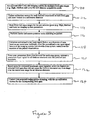
- a method for optimizing data acquisition signal-to-noise performance of imaging system 10 includes air-calibrating 110 imaging system 10 to pre-select a set of gains from the predetermined gains associated with each detector array 18 slice thickness. The pre-selected gains can be designated, for example, as high, medium and low for each slice thickness.
- Imaging system 10 parameters then are updated 112 with calibration vector data for each slice thickness corresponding to each pre-selected gain.
- calibration vector data can be stored in a calibration database and can be used for scan data processing based on scan mode selections. Imaging system 10 parameters then are updated with DAS 32 full input signal ranges 114 for the pre-selected gains.
- Lateral scout scanning is then performed 116 to obtain scout scan data pertaining to patient 22. Data quality is enhanced if antero-posterior scout scanning also is performed.
- Scout scan data is collected relative to a plurality of scout scan landmarks, e.g. patient 22 axial locations.
- Scout scan data then is used to determine at least one x-ray input signal factor that depends upon physical properties of patient 22 that affect x-rays detected by imaging system 10. Such properties include, for example, patient 22 dimensions, locations and positioning, x-ray attenuation densities and relative attenuation factors.
- Normalized x-ray input signal factors are determined 118 as functions of x-ray tube 14 voltage and current outputs, detector array 18 slice thickness, and DAS 32 gain. The normalized x-ray input signal factors are stored in imaging system 10 as a function of patient 22 axial location.
- the scanning parameters entered by the operator are used to estimate a maximum input signal 120 for all detector elements over patient 22 locations selected for scanning.
- the maximum input signal is determined by multiplying the normalized x-ray input signal factors for the selected patient 22 locations by requested x-ray tube 14 voltage and current output and detector array 18 slice thickness.
- a pre-selected DAS 32 gain then is determined 122 as the highest pre-selected gain that does not result in over-ranging when applied to the maximum input signal.
- Data acquired during scanning of patient 22 then is corrected 124 using the system parameters updated at calibration and corresponding to DAS 32 gain used for scanning.
- the above-described method improves image quality under low signal conditions by selection of data acquisition amplification gains and full input signal ranges based on, for example, such parameters as scanned object location, geometric dimension, and relative attenuation factor.
- Image quality also can be improved by selecting input signal ranges and gains based on such scanning techniques as selection of x-ray voltage and current outputs, slice thickness, detector/DAS sampling frequency, and gantry rotation speed.
- CT system described herein is a "third generation” system in which both the x-ray source and detector rotate with the gantry.
- CT systems including “fourth generation” systems wherein the detector is a full-ring stationary detector and only the x-ray source rotates with the gantry, may be used if individual detector elements are corrected to provide substantially uniform responses to a given x-ray beam.
- the system described herein performs an axial scan; however, the invention may be used with a helical scan although more than 360 degrees of data are required.
Landscapes
- Health & Medical Sciences (AREA)
- Life Sciences & Earth Sciences (AREA)
- Engineering & Computer Science (AREA)
- Medical Informatics (AREA)
- Optics & Photonics (AREA)
- Biomedical Technology (AREA)
- Biophysics (AREA)
- High Energy & Nuclear Physics (AREA)
- Veterinary Medicine (AREA)
- Nuclear Medicine, Radiotherapy & Molecular Imaging (AREA)
- Public Health (AREA)
- Pathology (AREA)
- Radiology & Medical Imaging (AREA)
- Physics & Mathematics (AREA)
- Heart & Thoracic Surgery (AREA)
- Molecular Biology (AREA)
- Surgery (AREA)
- Animal Behavior & Ethology (AREA)
- General Health & Medical Sciences (AREA)
- Pulmonology (AREA)
- Theoretical Computer Science (AREA)
- Apparatus For Radiation Diagnosis (AREA)
Applications Claiming Priority (2)
| Application Number | Priority Date | Filing Date | Title |
|---|---|---|---|
| US450362 | 1999-11-29 | ||
| US09/450,362 US6307912B1 (en) | 1999-11-29 | 1999-11-29 | Methods and apparatus for optimizing CT image quality with optimized data acquisition |
Publications (2)
| Publication Number | Publication Date |
|---|---|
| EP1103221A1 EP1103221A1 (en) | 2001-05-30 |
| EP1103221B1 true EP1103221B1 (en) | 2007-09-12 |
Family
ID=23787799
Family Applications (1)
| Application Number | Title | Priority Date | Filing Date |
|---|---|---|---|
| EP00310603A Expired - Lifetime EP1103221B1 (en) | 1999-11-29 | 2000-11-29 | Methods and apparatus for optimizing CT image quality with optimized data acquisition |
Country Status (6)
| Country | Link |
|---|---|
| US (1) | US6307912B1 (enExample) |
| EP (1) | EP1103221B1 (enExample) |
| JP (1) | JP4675472B2 (enExample) |
| CN (1) | CN1231182C (enExample) |
| DE (1) | DE60036355T2 (enExample) |
| IL (1) | IL139758A (enExample) |
Families Citing this family (8)
| Publication number | Priority date | Publication date | Assignee | Title |
|---|---|---|---|---|
| US6411673B1 (en) * | 2000-12-29 | 2002-06-25 | Ge Medical Systems Global Technology Company, Llc | Sampling rate scaling of calibration vectors in x-ray CT machines |
| JP4532005B2 (ja) * | 2001-03-09 | 2010-08-25 | 株式会社日立メディコ | X線ct装置及びその画像表示方法 |
| JP4387638B2 (ja) * | 2001-07-04 | 2009-12-16 | 株式会社東芝 | X線コンピュータ断層診断装置 |
| JP5438647B2 (ja) * | 2010-03-31 | 2014-03-12 | 富士フイルム株式会社 | 放射線画像システム |
| US8031828B1 (en) | 2010-04-30 | 2011-10-04 | General Electric Company | Method and apparatus for computed tomography |
| MX2014003685A (es) | 2011-09-30 | 2015-05-11 | Childrens Hosp Medical Center | Metodo para optimizacion coherente y verificable de una dosis de radiacion de tomografia computarizada (tc). |
| US20150086101A1 (en) * | 2013-09-25 | 2015-03-26 | General Electric Company | Method for organ localization |
| JP6571659B2 (ja) * | 2014-08-04 | 2019-09-04 | 株式会社日立製作所 | X線ct装置、データ処理装置及び投影データ生成方法 |
Family Cites Families (17)
| Publication number | Priority date | Publication date | Assignee | Title |
|---|---|---|---|---|
| JPS6152860A (ja) * | 1984-08-24 | 1986-03-15 | 株式会社 日立メデイコ | X線ct装置 |
| JPH01299535A (ja) * | 1988-05-30 | 1989-12-04 | Toshiba Corp | データ収集装置 |
| US5220589A (en) * | 1991-07-18 | 1993-06-15 | General Electric Company | Correction circuit for a floating-point amplifier |
| JP2624927B2 (ja) * | 1992-10-06 | 1997-06-25 | 株式会社東芝 | X線ct装置 |
| US5416815A (en) * | 1993-07-02 | 1995-05-16 | General Electric Company | Adaptive filter for reducing streaking artifacts in x-ray tomographic images |
| US5379333A (en) | 1993-11-19 | 1995-01-03 | General Electric Company | Variable dose application by modulation of x-ray tube current during CT scanning |
| US5400378A (en) | 1993-11-19 | 1995-03-21 | General Electric Company | Dynamic dose control in multi-slice CT scan |
| US5450462A (en) * | 1993-11-19 | 1995-09-12 | General Electric Company | Modulation of x-ray tube current during CT scanning with modulation limit |
| US5430785A (en) * | 1994-04-11 | 1995-07-04 | General Electric Company | Detector channel gain calibration using focal spot wobble |
| JPH07303632A (ja) * | 1994-05-11 | 1995-11-21 | Ge Yokogawa Medical Syst Ltd | Ct装置 |
| US5933540A (en) | 1995-05-11 | 1999-08-03 | General Electric Company | Filter system and method for efficiently suppressing noise and improving edge definition in a digitized image |
| CA2184237A1 (en) * | 1995-09-08 | 1997-03-09 | Jay A. Stein | X-ray bone densitometry |
| JPH1021372A (ja) * | 1996-07-05 | 1998-01-23 | Toshiba Corp | X線ct装置 |
| JP3673041B2 (ja) * | 1996-11-21 | 2005-07-20 | ジーイー横河メディカルシステム株式会社 | Ctイメージング方法およびx線ct装置 |
| US5828719A (en) | 1996-12-23 | 1998-10-27 | General Electric Company | Methods and apparatus for modulating data acquisition system gain |
| US5734691A (en) * | 1996-12-23 | 1998-03-31 | General Electric Company | Detector z-axis gain non-uniformity correction in a computed tomography system |
| JPH10211195A (ja) * | 1997-01-30 | 1998-08-11 | Shimadzu Corp | X線ct装置 |
-
1999
- 1999-11-29 US US09/450,362 patent/US6307912B1/en not_active Expired - Lifetime
-
2000
- 2000-11-19 IL IL13975800A patent/IL139758A/en not_active IP Right Cessation
- 2000-11-28 JP JP2000360411A patent/JP4675472B2/ja not_active Expired - Fee Related
- 2000-11-29 EP EP00310603A patent/EP1103221B1/en not_active Expired - Lifetime
- 2000-11-29 DE DE60036355T patent/DE60036355T2/de not_active Expired - Lifetime
- 2000-11-29 CN CNB001342916A patent/CN1231182C/zh not_active Expired - Fee Related
Non-Patent Citations (1)
| Title |
|---|
| None * |
Also Published As
| Publication number | Publication date |
|---|---|
| CN1298098A (zh) | 2001-06-06 |
| IL139758A0 (en) | 2002-02-10 |
| DE60036355T2 (de) | 2008-06-12 |
| US6307912B1 (en) | 2001-10-23 |
| DE60036355D1 (de) | 2007-10-25 |
| IL139758A (en) | 2004-06-20 |
| CN1231182C (zh) | 2005-12-14 |
| EP1103221A1 (en) | 2001-05-30 |
| JP2001258875A (ja) | 2001-09-25 |
| JP4675472B2 (ja) | 2011-04-20 |
Similar Documents
| Publication | Publication Date | Title |
|---|---|---|
| US5457724A (en) | Automatic field of view and patient centering determination from prescan scout data | |
| US6421411B1 (en) | Methods and apparatus for helical image artifact reduction | |
| JP4367884B2 (ja) | 石灰化のレベル付けを行う方法と装置 | |
| US5696807A (en) | Methods and apparatus for modulating x-ray tube current | |
| US5400378A (en) | Dynamic dose control in multi-slice CT scan | |
| US6035012A (en) | Artifact correction for highly attenuating objects | |
| US6370218B1 (en) | Methods and systems for determining x-ray beam position in multi-slice computed tomography scanners | |
| US6366638B1 (en) | Methods and apparatus for CT scout image processing | |
| EP1078599B1 (en) | Methods and apparatus for positioning a CT imaging x-ray beam | |
| US6493416B1 (en) | Method and apparatus for noise reduction in computed tomographic systems | |
| US5473656A (en) | Computed tomography system with correction for z-axis detector non-uniformity | |
| US6310938B1 (en) | Methods and apparatus for calibrating CT x-ray beam tracking loop | |
| EP1114617B1 (en) | Methods and apparatus for automatic patient positioning | |
| US5828719A (en) | Methods and apparatus for modulating data acquisition system gain | |
| US6134292A (en) | Methods and apparatus for reducing z-axis non-uniformity artifacts | |
| US6493646B1 (en) | High order primary decay correction for CT imaging system detectors | |
| JP2002530140A (ja) | X線ビームの動きを補正するための方法および装置 | |
| US5761257A (en) | Normalizing projection data in a computed tomography system | |
| US5812628A (en) | Methods and apparatus for detecting partial volume image artifacts | |
| US6269139B1 (en) | Methods and apparatus for pre-filtering weighting in image reconstruction | |
| EP1103221B1 (en) | Methods and apparatus for optimizing CT image quality with optimized data acquisition | |
| US6418183B1 (en) | Methods and apparatus for two-pass CT imaging | |
| JPH10295687A (ja) | 物体の画像を再構成する方法及びシステム | |
| US6418185B1 (en) | Methods and apparatus for time-multiplexing data acquisition | |
| IL138652A (en) | System for dynamic adjustment of a component in the imaging system of computerized tomography |
Legal Events
| Date | Code | Title | Description |
|---|---|---|---|
| PUAI | Public reference made under article 153(3) epc to a published international application that has entered the european phase |
Free format text: ORIGINAL CODE: 0009012 |
|
| AK | Designated contracting states |
Kind code of ref document: A1 Designated state(s): DE NL |
|
| AX | Request for extension of the european patent |
Free format text: AL;LT;LV;MK;RO;SI |
|
| 17P | Request for examination filed |
Effective date: 20011130 |
|
| AKX | Designation fees paid |
Free format text: DE NL |
|
| 17Q | First examination report despatched |
Effective date: 20030710 |
|
| GRAP | Despatch of communication of intention to grant a patent |
Free format text: ORIGINAL CODE: EPIDOSNIGR1 |
|
| GRAS | Grant fee paid |
Free format text: ORIGINAL CODE: EPIDOSNIGR3 |
|
| GRAA | (expected) grant |
Free format text: ORIGINAL CODE: 0009210 |
|
| AK | Designated contracting states |
Kind code of ref document: B1 Designated state(s): DE NL |
|
| REF | Corresponds to: |
Ref document number: 60036355 Country of ref document: DE Date of ref document: 20071025 Kind code of ref document: P |
|
| PLBE | No opposition filed within time limit |
Free format text: ORIGINAL CODE: 0009261 |
|
| STAA | Information on the status of an ep patent application or granted ep patent |
Free format text: STATUS: NO OPPOSITION FILED WITHIN TIME LIMIT |
|
| 26N | No opposition filed |
Effective date: 20080613 |
|
| PGFP | Annual fee paid to national office [announced via postgrant information from national office to epo] |
Ref country code: DE Payment date: 20101126 Year of fee payment: 11 |
|
| PGFP | Annual fee paid to national office [announced via postgrant information from national office to epo] |
Ref country code: NL Payment date: 20111129 Year of fee payment: 12 |
|
| REG | Reference to a national code |
Ref country code: NL Ref legal event code: V1 Effective date: 20130601 |
|
| PG25 | Lapsed in a contracting state [announced via postgrant information from national office to epo] |
Ref country code: NL Free format text: LAPSE BECAUSE OF NON-PAYMENT OF DUE FEES Effective date: 20130601 |
|
| REG | Reference to a national code |
Ref country code: DE Ref legal event code: R119 Ref document number: 60036355 Country of ref document: DE Effective date: 20130601 |
|
| PG25 | Lapsed in a contracting state [announced via postgrant information from national office to epo] |
Ref country code: DE Free format text: LAPSE BECAUSE OF NON-PAYMENT OF DUE FEES Effective date: 20130601 |