EP1102364A2 - Nachrichtenstecker - Google Patents
Nachrichtenstecker Download PDFInfo
- Publication number
- EP1102364A2 EP1102364A2 EP00310120A EP00310120A EP1102364A2 EP 1102364 A2 EP1102364 A2 EP 1102364A2 EP 00310120 A EP00310120 A EP 00310120A EP 00310120 A EP00310120 A EP 00310120A EP 1102364 A2 EP1102364 A2 EP 1102364A2
- Authority
- EP
- European Patent Office
- Prior art keywords
- communication plug
- crosstalk
- plug
- communication
- cable
- Prior art date
- Legal status (The legal status is an assumption and is not a legal conclusion. Google has not performed a legal analysis and makes no representation as to the accuracy of the status listed.)
- Granted
Links
Images


Classifications
-
- H—ELECTRICITY
- H01—ELECTRIC ELEMENTS
- H01R—ELECTRICALLY-CONDUCTIVE CONNECTIONS; STRUCTURAL ASSOCIATIONS OF A PLURALITY OF MUTUALLY-INSULATED ELECTRICAL CONNECTING ELEMENTS; COUPLING DEVICES; CURRENT COLLECTORS
- H01R13/00—Details of coupling devices of the kinds covered by groups H01R12/70 or H01R24/00 - H01R33/00
- H01R13/646—Details of coupling devices of the kinds covered by groups H01R12/70 or H01R24/00 - H01R33/00 specially adapted for high-frequency, e.g. structures providing an impedance match or phase match
- H01R13/6461—Means for preventing cross-talk
- H01R13/6467—Means for preventing cross-talk by cross-over of signal conductors
-
- H—ELECTRICITY
- H01—ELECTRIC ELEMENTS
- H01R—ELECTRICALLY-CONDUCTIVE CONNECTIONS; STRUCTURAL ASSOCIATIONS OF A PLURALITY OF MUTUALLY-INSULATED ELECTRICAL CONNECTING ELEMENTS; COUPLING DEVICES; CURRENT COLLECTORS
- H01R24/00—Two-part coupling devices, or either of their cooperating parts, characterised by their overall structure
- H01R24/60—Contacts spaced along planar side wall transverse to longitudinal axis of engagement
- H01R24/62—Sliding engagements with one side only, e.g. modular jack coupling devices
- H01R24/64—Sliding engagements with one side only, e.g. modular jack coupling devices for high frequency, e.g. RJ 45
Definitions
- the present invention relates generally to the field of modular communication plugs and, more particularly, to the generation of complementary crosstalk in a communication plug such that performance with connector jacks is optimized.
- plugs and jacks that are most commonly used in interconnecting cables and hardware, such as distribution modules generally include as many as eight wires (four wire pairs), and, in some instances, even more, that are necessarily oriented both parallel and close together, a condition that leads to excessive crosstalk, even over short distances, and which is exacerbated as the frequency of the signals or the data rate is increased.
- the present invention is generally directed to a communication plug having predetermined crosstalk characteristics.
- the crosstalk characteristics in communication plugs produced using the present invention are of a higher degree of uniformity than is found in current communication plugs.
- the present invention comprises an assembly of crossover electrical connectors which produce a set level of crosstalk such that the compensating crosstalk in jacks is optimized to achieve higher data transmission rates.
- An eight wire communication cable used in high frequency data communication is typically comprised of four sets of helically wound twisted-pairs of insulated conducting wires surrounded by a protective jacket.
- a portion of the cable jacket surrounding the conducting wires is removed from one end, and the four sets of twisted-pair insulated conducting wires are partially unwound.
- the wires are arranged in a specific order corresponding to an industry standard, aligned with a receiving opening in the back of the communication plug and with their respective receiving slots within the communication plug, inserted into the communication plug, and secured to the communication plug. Electrical connectors are attached to the wires, through slots in the top of the communication plug.
- the electrical connectors are adapted to make electrical contact between associated jack springs in the jack and with the insulated conducting wires in the plug.
- each terminating a cable In order for two modular communication plugs, each terminating a cable, to have uniform crosstalk characteristics the insulated conducting wires of the cable need to be dressed (untwisted, straightened, and arranged) in an essentially identical manner. Communication plugs which are identical, except for the dressing of the individual conducting wires, will often exhibit different crosstalk characteristics.
- the present invention eliminates much of the dressing of the insulated conducting wires of the cable during the assembly of a communication plug.
- the four sets of twisted-pairs are inserted into the rear of the plug housing, through the receiving opening in the rear of the housing.
- the twisted-pairs are aligned with their respective receiving slots, and an electrical connector in the form of a blade is attached to each wire.
- the electrical connectors are adapted at one end so as to make electrical contact with an insulated conducting wire, and the other end is adapted so as to make electrical contact with a jack spring.
- one or more electrical connectors of an assembly of connectors may crossover, or crossunder, one or more adjacent electrical connectors such that the location of the jack end portion of each of the electrical connectors corresponds to the industry standard.
- the electrical connector assembly is formed such that the electrical connectors do not make electrical contact in the crossover region.
- An advantage of the present invention is that the set of twisted-pairs are dressed in substantially the same manner in every communication plug.
- the twisted-pairs are cut to the same length and attached to the assembly of electrical connectors. Because the conducting wires remain as twisted-pairs within the plug instead of being juxtaposed in a straight parallel manner, the crosstalk between the conducting pairs of wires within the communication plug is reduced.
- the electrical connectors are manufactured uniformly, and consequently the crosstalk characteristics between different sets of electrical connectors in different plugs are essentially identical.
- Use of the present invention eliminates the variations in the crosstalk characteristics introduced by the dressing of individual insulated conducting wires in different communication plugs, thereby producing greater uniformity in the crosstalk characteristics of different communication plugs.
- Another advantage is the time saving; it takes less time to align properly the four sets of twisted-pairs than it does to dress and align the individual wires.
- the crosstalk generated in the plug can be fixed to a desired level by modifying certain engineerable parameters such as the size and shape of the ends of electrical connector.
- Other engineerable parameters in the electrical connector include the length of the arm connecting, the size and shape of the insulation piercing end, and the spacing between adjacent ends, and the type of the material from which the electrical connector is made.
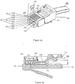
- Figures 1A, 1B, and 1C illustrate a current modular or prior art communication plug 100.
- Figure 1A is a perspective view of modular communication plug 100 terminating communication cable 200.
- Figure 1B is a cross sectional view of Figure 1A with electrical connector 150 inserted into slot 143, and Figure 1C is a view of Figure 1A taken from above.
- modular communication plug 100 comprises a housing 110 having a first end 120, a second end 130, and an upper surface 140. Extending from first end 120, a portion of upper surface 140 has a plurality of slots 141 formed therein for receiving associated jack contacts (not shown). Each jack contact receiving slot 141 has receiving slot 143 formed therein for receiving an electrical connector 150. Electrical connector slot 143 is formed to receive electrical connector 150 and to be in communication with wire receiving slot 132. Wire receiving slot 132 is formed to receive an insulated conducting wire 221, and to be in communication with cable receiving opening 131 formed in the second end 130.
- modular communication plug 100 terminates an eight wire communication cable 200 in accordance with industry standards.
- Terminal wiring assignments for modular plugs and jacks are specified in ANSI/EIA/TIA-568-1991 which is the Commercial Building Telecommunications Wiring Standard.
- the Commercial Building Telecommunications Wiring Standard associates individual wire-pairs with specific terminals for an eight-position modular communication plug; jack receiving slots 142e and 142f form terminal pair P1, slots 142a and 142b form terminal pair P2, slots 142c and 142d form terminal pair P3 and slots 142g and 142h form terminal pair P4.
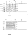
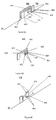
- Communication cable 200 is shown from above in various stages of dressing, so as to be properly received by modular communication plug 100.
- Communication cable 200 comprises a jacket 210, and four sets of helically twisted-pairs of wires P1'-P4', corresponding to terminal pairs P1-P4 in modular communication plug 100 shown in Figure 1A.
- wire 220d is positioned such that wire 220d traverses a portion of wires 220e-220f in region 225, and wire end 220d' interposes wire ends 220f' and 220g'.
- wires 220a - 220h are cut along the dashed line 240, shown in Figure 2C, communication cable 200 is dressed so as to be properly received by modular communication plug 100.
- Wires 220c and 220d which form wire pair P3', straddle wires 220e and 220f, which form wire pair P1', just as terminal pair P3 straddles terminal pair P1 in modular communication plug 100, in accordance with the industry standard ANSI/EIA/TIA-568-1991.
- modular communication plug 100 is shown from above terminating communication cable 200.
- a portion of upper surface 140 has been cut away exposing end region 225 of wires 220a-220h; the boundary of the cut away portion is represented by dashed line 144.
- End region 225 of cable 200 has been inserted into modular communication plug 100 through cable receiving opening 131, and wires 220a-220h have been properly received by their respective wire receiving slots 132.
- Electrical connector 150 has been inserted into electrical connector receiving slot 143.
- a plurality of tangs 151 protrude from the bottom region of electrical connector 150. Tangs 151 are adapted so as to make electrical contact with insulated conducting wire 221.
- U.S. Patent 4,650, 269 hereby incorporated by reference, discloses an electrical connector used in modular communication plugs with insulation piercing tangs and adapted to make electrical contact with a jack spring.
- the level of crosstalk is largely influenced by the distance between adjacent conductors. This is because the degree of capacitive and inductive coupling between adjacent conductors, decreases roughly as the square of the distance separating the conductors, and is also strongly influenced by both the distance between and the length along which such conductors are juxtaposed.
- wires 220a-220h are essentially closely juxtaposed in a parallel manner; a configuration leading to high levels of crosstalk.
- wire pair P3' straddles wire pair P1' and is adjacent to wire pairs P2' and P4', thereby resulting in a high level of crosstalk between wire pair P3' and all of the other wire pairs.
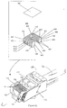
- a modular communication plug 300 including an embodiment of an electrical connector assembly is illustrated in Figures 3A - 3C.
- Figure 3A a perspective view of electrical connector 400 and a partially exploded perspective view of modular communication plug 300 terminating communication cable 200 is illustrated.
- Figures 3B and 3C modular communication plug 300, with electrical connector assembly 400 inserted therein, is shown terminating communication cable 200 in a cross sectional view, taken along the line 2 - 2 in Figure 3A, and a top view respectively.
- Figures 3A - 3C will be used to illustrate the manner in which communication cable 200, modular communication plug 300, and electrical connector assembly are mated and interrelated.
- modular communication plug 300 comprises a housing 310 having a first end 320, a second end 330, an upper surface 340 having a opening 350 formed therein. Extending from first end 320 and adjacent thereto, a portion of upper surface 340 has a plurality of slots 341 formed therein for receiving associated jack contacts (not shown). Each jack receiving slot 341 being in communication with electrical connector receiving slot 342 formed to receive electrical connector 410. Opening 350 being in communication with twisted-pair wire receiving slot 332 formed to receive twisted-pair wires 251, and to be in communication with cable receiving opening 331 formed in the second end 330 of modular communication plug housing 410. Ridge 370 interposes jack receiving slots 342 and wire receiving slots 332, and has an upper surface 372 with a notch 373 formed therein.
- the electrical connector assembly 400 of the invention comprises a plurality of conductive blades 410 having first ends 420 and second ends 430; first ends 420 and second ends 430 being arranged in an essentially parallel manner.
- Conductive blades 410 are made from electrically conducting materials suitable for being formed into the desired shape: for example, copper alloy in the form of a rolled strip stock can be stamped into conductive blades 410.
- conductive blade 411d is adapted to crossover conductive blades 411e and 411f such that there is no electrical contact between conductive blades 411 d , 411 e, and 411 f.
- conductive blades 410 are comprised of three integral portion portions; jack contact portion 440, arm portion 450, and conductor piercing portion 460.
- Jack contact portion 440 comprises a portion having first end 420, a second end 429, and essentially flat upper surface 421, two essentially flat planar parallel surfaces 422 and 423. Upper surface 421 is adapted to make electrical contact with jack springs (not shown). Jack portion 440 is adapted to be received by electrical connector receiving slot 342.
- arm portion 450 extends from second end 429 of jack portion 440 to the first end 439 of piercing portion 430.
- the arm portion 450 of conductive blades 411e and 411f is offset from the upper surface 421 of the jack contact portion 440 and offset from the upper surface 431 of the piercing portion 460. Offsetting the arm portion_450 of conductive blades 41 le and 411f in this manner creates a clearance notch, whereby arm portion 450 of conductive blade 41 1d crosses over the offset arm portion 450 of conductive blades 41 le and 411f without making electrical contact therewith.
- piercing portion 460 comprises a portion extending from a first end 439 to end 430, having an upper surface 431, two essentially flat planar parallel surfaces 432 and 433, and a bottom region 434. Protruding in a downward direction from bottom 434 is a plurality of tangs 435 formed to pierce the insulation surrounding an insulated conducting wire and make electrical contact with the conducting wire.
- U.S. Patent 4,650, 269 discloses an electrical connector used in modular communication plugs with insulation piercing tangs and adapted to make electrical contact with a jack spring.
- Communication cable 200 must be dressed so as to be properly mated with modular communication plug 300.
- a portion of jacket 210 is removed from the end region 225 exposing twisted-pairs P1'-P4'.
- Wires 221 are cut along the dashed line 250 so that the wire ends 220a' - 220h' are in sequential order as shown in Figure 2D.
- communication cable 200 is properly dressed so as to be mated with modular communication plug 300.
- Figure 3C shows a top view of modular communication plug 300 and communication cable 200 properly mated.
- end region 225 of communication cable 200 is aligned with cable receiving opening 331 formed in the rear surface 330 of modular communication plug 300 and twisted-pairs P1' - P4' are aligned with their respective receiving slots 332. Then end region 225 of communication cable 200 is inserted into cable receiving opening 331 such that wire ends 220a' - 220h' abut wall 371 of ridge 370, as illustrated in Figure 3C.
- electrical connector assembly 400 is inserted into modular communication plug 300 such that second ends 430 of electrical connector 400 are received by opening 350, and first ends 420 of electrical connector 400 are received by their respective jack portion receiving slots 342, as shown in Figure 3B.
- Crossunder conductive blades 411e and 411f are inserted before crossover conductive blade 411d is inserted.
- notch 373 of ridge 370 of modular communication plug 300 provides clearance for the offset arm portion of conductive blades 411e and 411f.
- jack contact portion 440 is seated in receiving slot 342 and tangs 435 are in electrical contact with conducting wire 222.
- conductive blade 411d crosses over conductive blades 41 le and 411f such that first end 420d of conductive blade 411d interposes first end 420f and first end 420g, while the second end 430d interposes second ends 430c and 430d.
- the first end pairs P1 - P4 electrically communicate with twisted-wire pairs P1'-P2' respectively and are arranged in accordance with industry standards.
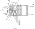
- Figure 3C shows another embodiment of modular communication plug 300.
- Ridge 370 has a plurality of slots 374 formed therein for receiving arm portion 450 of conductive blades 410. After all of the conductive blades 410 have been inserted_into modular communication plug 300, electrical cover panel 360 is pressed into opening 350.
- Conductive blade 411d crosses over conductive blades 411e and 411f in a predetermined and fixed manner; arm portion 450d crossing over arm portion 450e at region 501 and crossing over arm portion 450f in region 502.
- Arm bodies 450d and 450e, and 450d and 450f are separated by a vertical distance such that conductive blade 410d does not make electrical contact with conductive blade 410e in crossover region 501 nor with conductive blade 410f in crossover region 502.
- the fixed manner in which arm portion 450d crosses over arm bodies 450e and 450f provides consistent crosstalk characteristics in all electrical connector assemblies.
- the arm portion 450 of conductor blade 410 is engineered such that the jack receiving portion 440 and the conductor piercing portion 460 are in close proximity to each other and with the first end 320. Therefore, electrical connector assembly 400 generates crosstalk in the first end 320 of modular communication plug 300,and reduces the crosstalk from the conductive wires because the wires are twisted-pairs.
- Jack receiving portion 440 is an essentially flat parallel plate and when carrying electrical signals, the jack receiving portion of the conductive blades form capacitors causing capacitive coupling of signals between the jack receiving ends.
- the size and the shape of jack receiving portions 440 and of the conductive piercing portions are parameters for generating the desired level of crosstalk.
- FIG. 4A-4C Two embodiments of conductive members of the present invention are illustrated in Figures 4A-4C for reducing the crosstalk at the piercing ends 430.
- a perspective view of electrical connectors 600 and 700 parallel to longitudinal axis 10 is shown in Figure 4A.
- the jack contact bodies 440 are arranged in an essentially parallel manner, as they were in electrical connector assembly 400.
- the longitudinal component of arm lengths of arms 650 and 750 are measured from second end 429 of jack contact portion 440 to first end 439 of piercing portion 460 along the longitudinal axis 10.
- Longitudinal arm length 751 is greater than longitudinal arm 651 such that the piercing bodies 460 extending from first end 439 to second end 420 are no longer adjacent and parallel; thereby reducing the capacitive crosstalk.
- FIG. 4B A perspective view of electrical connector member 800 is shown in Figure 4B.
- Piercing portion 860 of electrical connector member 800 comprises a portion extending from first end 439 to end 430, having an upper surface 431, and bottom 434 region, and two essentially flat planar parallel surfaces 432 and 433 with a opening 801 formed therethrough. Opening 801 reduces the surface area piercing portion 860, thereby reducing the capacitive coupling between adjacent electrical connector members.
- piercing portion 460 of electrical connector member 900 has tangs 435 and 437 protruding from bottom region 434 and top region 436 respectively.
- piercing portion 460 is displaced from longitudinal axis 10 by a transverse amount d x .
- Rotating electrical connector member 900 by 180° about longitudinal axis 10 will result in the transverse displacement of piercing portion 460 to be -d x , and in tangs 437 to be orientated in a generally downward direction.
- Electrical connector 900 can be used in communication plugs requiring either a positive or negative transverse displacement of piercing portion 460 relative to longitudinal axis 10.
- FIGS 5A - 5E illustrate, from a perspective view and a view from above, all of the above mentioned electrical connectors.
- straight electrical connector 1000 having a plurality of tangs 435 and 437 protruding from lower region 434 and upper region 436 respectively, is illustrated after being formed from a stamp.
- Arm 450 comprising a generally flat planar upper surface 451, a generally flat lower surface 452, and two generally flat planar side surfaces 453 and 452, extending in a generally straight manner along longitudinal axis 10 from second end 429 of contact portion 440 to first end 439 of piercing portion 460.
- the length of arm 450, as measured along longitudinal axis 10 is approximately L 1 .
- Electrical connector 1000 can be formed into a crossing member, either over or under, by appropriately bending arm 450.
- electrical connector 1000(b) is illustrated with arm 450 having a first bend 455 and a second bend 456, separated by a distance x 1 , each bend essentially flat and planar with respect to upper surface 451.
- the angle defining first bend 455 is an acute angle a and the angle defining second bend 456 is an acute angle approximately -a.
- Second bend 456 compensates for first bend 455 such that sides 432 and 433 of piercing portion 460 are essentially parallel to longitudinal axis 10, and piercing portion 460 is transversely displaced from longitudinal axis 10 by an amount d 1 .
- the transverse displacement d 1 of piercing portion 460 is a function the angle defining the first and second bends and of the distance separating the bends.
- electrical connector 1000c is illustrated wherein arm 450 having a first bend 457 and a second bend 458 separated by a distance x 2 , and each bend is formed such that surfaces 451 and 452 remain essentially flat and planar.
- first bend 457 is an acute angle ⁇
- second bend 458 is an acute angle approximately - ⁇ .
- First and second bends 457 and 458 are formed such that piercing portion 460 is essentially parallel to longitudinal axis 10 and transversely displaced from longitudinal axis 10 by an amount d 2 .
- electrical connector 1000c When electrical connector 1000c is orientated as previously described and properly aligned with electrical connector 1000b the connectors form a crossing pair, electrical connector 1000b crosses over and electrical connector 1000c crosses under.
- Figure 5E illustrates electrical connector crossing under two electrical connectors of type 1000b. If electrical connector 1000b had been rotated about longitudinal axis 10 instead of electrical connector 1000c, then role of the electrical connectors within the crossing pair would be reversed. Thus, all of the electrical connectors can be formed from a stamped electrical connector having tangs protruding from the top region and the bottom region of the piercing portion.
- the communication plug can be engineered during the design process to generate complementary crosstalk to match the characteristics of the jack or connector to which the plug will be mated.
- the complementary crosstalk is generated at the nose or front of the plug where the members comprising the electrical connector assembly engage the jack springs in the jack or connector thus minimizing any signal propagation delay.
- Several engineerable parameters are identified that can be adjusted during the design and manufacturing phases of the plug to fix the complementary crosstalk level.
- a dielectric can be inserted into regions 501 and 502 to prevent electrical contact between conductive blades 411d, 411e and 411f;
- conductive blades 410 can be heated and inserted into modular communication plug 300 such that arm portion 450 melts a portion of ridge 470 thereby insulating the arm portion with the dielectric forming ridge 370.
- jack receiving slot 341 would not have conductive blade receiving slot 342 formed therein.
- Conductive blade 410 would be heated, such that when heated conductive blade 410 is inserted into modular communication plug 300, a portion of heated conductive blade 410 would melt a portion of the dielectric material in the bottom of jack receiving slot 341. Upon cooling, a portion of conductive blade 410 would be embedded in the solidified dielectric material and fixedly held therein. All such variations and modifications are intended to be included herein within the scope of the present invention, as set forth in the following claims.
Applications Claiming Priority (2)
| Application Number | Priority Date | Filing Date | Title |
|---|---|---|---|
| US09/441,401 US6276954B1 (en) | 1999-11-16 | 1999-11-16 | Communication plug having consistent and set levels of complementary crosstalk |
| US441401 | 1999-11-16 |
Publications (3)
| Publication Number | Publication Date |
|---|---|
| EP1102364A2 true EP1102364A2 (de) | 2001-05-23 |
| EP1102364A3 EP1102364A3 (de) | 2002-08-14 |
| EP1102364B1 EP1102364B1 (de) | 2006-08-16 |
Family
ID=23752738
Family Applications (1)
| Application Number | Title | Priority Date | Filing Date |
|---|---|---|---|
| EP00310120A Expired - Lifetime EP1102364B1 (de) | 1999-11-16 | 2000-11-15 | Nachrichtenstecker |
Country Status (6)
| Country | Link |
|---|---|
| US (1) | US6276954B1 (de) |
| EP (1) | EP1102364B1 (de) |
| JP (1) | JP3672813B2 (de) |
| AU (1) | AU769688B2 (de) |
| CA (1) | CA2325957C (de) |
| DE (1) | DE60030067T2 (de) |
Cited By (3)
| Publication number | Priority date | Publication date | Assignee | Title |
|---|---|---|---|---|
| CN103515756A (zh) * | 2012-06-16 | 2014-01-15 | 富士康(昆山)电脑接插件有限公司 | 线缆连接器组件及其制造方法 |
| CN103545664A (zh) * | 2012-07-12 | 2014-01-29 | 富士康(昆山)电脑接插件有限公司 | Rj插头连接器 |
| EP3457503A1 (de) * | 2009-06-11 | 2019-03-20 | CommScope, Inc. of North Carolina | Kommunikationsstecker mit kondensatoren zur injektion von störender übersprechung nach einer stecker-buchsen-steckstelle sowie entsprechende steckverbinder und verfahren |
Families Citing this family (16)
| Publication number | Priority date | Publication date | Assignee | Title |
|---|---|---|---|---|
| TW549673U (en) * | 2002-12-11 | 2003-08-21 | Yu-He Liang | Connection terminal structure improvement |
| BRPI0416827A (pt) * | 2003-11-21 | 2007-02-13 | Leviton Manufacturing Co | painel de conexão com sistema de redução de fala cruzada e método |
| US20050221678A1 (en) | 2004-02-20 | 2005-10-06 | Hammond Bernard Jr | Methods and systems for compensating for alien crosstalk between connectors |
| US10680385B2 (en) | 2004-02-20 | 2020-06-09 | Commscope Technologies Llc | Methods and systems for compensating for alien crosstalk between connectors |
| US7187766B2 (en) | 2004-02-20 | 2007-03-06 | Adc Incorporated | Methods and systems for compensating for alien crosstalk between connectors |
| CA2647704A1 (en) * | 2008-12-22 | 2010-06-22 | Belden Cdt (Canada) Inc. | Coupler connector |
| US8145442B2 (en) * | 2009-01-30 | 2012-03-27 | Synopsys, Inc. | Fast and accurate estimation of gate output loading |
| US8993887B2 (en) * | 2009-11-09 | 2015-03-31 | L-Com, Inc. | Right angle twisted pair connector |
| US8764476B1 (en) | 2012-12-06 | 2014-07-01 | Frank Ma | Transmission connector |
| US9246265B2 (en) | 2013-03-12 | 2016-01-26 | Commscope Technologies Llc | Notched contact for a modular plug |
| US9543729B2 (en) | 2013-08-19 | 2017-01-10 | Sullstar Technologies, Inc | Electrical connector with removable external load bar, and method of its use |
| JP6130279B2 (ja) * | 2013-09-24 | 2017-05-17 | 株式会社Soken | コネクタ |
| US9640924B2 (en) | 2014-05-22 | 2017-05-02 | Panduit Corp. | Communication plug |
| TWM536801U (zh) * | 2016-10-21 | 2017-02-11 | Jyh Eng Technology Co Ltd | 網路插頭結構 |
| USD815601S1 (en) * | 2016-12-02 | 2018-04-17 | You Hung International Co., Ltd. | Cable connector |
| JP7041941B2 (ja) * | 2017-10-31 | 2022-03-25 | サンワサプライ株式会社 | ツイストペアケーブル用コネクタ |
Citations (3)
| Publication number | Priority date | Publication date | Assignee | Title |
|---|---|---|---|---|
| US5284447A (en) * | 1993-03-29 | 1994-02-08 | Virginia Plastics Company, Inc. | Contact terminal for modular plug |
| US5762516A (en) * | 1995-06-09 | 1998-06-09 | Minnesota Mining And Manufacturing Company | Contact and terminal connector having the contact |
| US5967828A (en) * | 1995-05-16 | 1999-10-19 | The Whitaker Corporation | Modular plug for high speed data transmission |
Family Cites Families (6)
| Publication number | Priority date | Publication date | Assignee | Title |
|---|---|---|---|---|
| US4650269A (en) * | 1985-09-16 | 1987-03-17 | At&T Information Systems Inc. | Modular plug connector |
| US5226835A (en) * | 1992-08-06 | 1993-07-13 | At&T Bell Laboratories | Patch plug for cross-connect equipment |
| US5601447A (en) * | 1995-06-28 | 1997-02-11 | Reed; Carl G. | Patch cord assembly |
| US5791943A (en) * | 1995-11-22 | 1998-08-11 | The Siemon Company | Reduced crosstalk modular outlet |
| AU716436B2 (en) * | 1995-12-25 | 2000-02-24 | Matsushita Electric Works Ltd. | Connector |
| US5938479A (en) * | 1997-04-02 | 1999-08-17 | Communications Systems, Inc. | Connector for reducing electromagnetic field coupling |
-
1999
- 1999-11-16 US US09/441,401 patent/US6276954B1/en not_active Expired - Fee Related
-
2000
- 2000-11-14 AU AU71614/00A patent/AU769688B2/en not_active Ceased
- 2000-11-14 CA CA002325957A patent/CA2325957C/en not_active Expired - Fee Related
- 2000-11-15 DE DE60030067T patent/DE60030067T2/de not_active Expired - Lifetime
- 2000-11-15 EP EP00310120A patent/EP1102364B1/de not_active Expired - Lifetime
- 2000-11-16 JP JP2000348921A patent/JP3672813B2/ja not_active Expired - Fee Related
Patent Citations (3)
| Publication number | Priority date | Publication date | Assignee | Title |
|---|---|---|---|---|
| US5284447A (en) * | 1993-03-29 | 1994-02-08 | Virginia Plastics Company, Inc. | Contact terminal for modular plug |
| US5967828A (en) * | 1995-05-16 | 1999-10-19 | The Whitaker Corporation | Modular plug for high speed data transmission |
| US5762516A (en) * | 1995-06-09 | 1998-06-09 | Minnesota Mining And Manufacturing Company | Contact and terminal connector having the contact |
Cited By (5)
| Publication number | Priority date | Publication date | Assignee | Title |
|---|---|---|---|---|
| EP3457503A1 (de) * | 2009-06-11 | 2019-03-20 | CommScope, Inc. of North Carolina | Kommunikationsstecker mit kondensatoren zur injektion von störender übersprechung nach einer stecker-buchsen-steckstelle sowie entsprechende steckverbinder und verfahren |
| EP2441135B1 (de) * | 2009-06-11 | 2019-08-07 | Commscope Inc. Of North Carolina | Kommunikationsstecker mit kondensatoren zur injektion von störender übersprechung nach einer stecker-buchsen-steckstelle sowie entsprechende steckverbinder und verfahren |
| CN103515756A (zh) * | 2012-06-16 | 2014-01-15 | 富士康(昆山)电脑接插件有限公司 | 线缆连接器组件及其制造方法 |
| CN103515756B (zh) * | 2012-06-16 | 2016-08-10 | 富士康(昆山)电脑接插件有限公司 | 线缆连接器组件及其制造方法 |
| CN103545664A (zh) * | 2012-07-12 | 2014-01-29 | 富士康(昆山)电脑接插件有限公司 | Rj插头连接器 |
Also Published As
| Publication number | Publication date |
|---|---|
| CA2325957C (en) | 2005-01-11 |
| AU7161400A (en) | 2001-05-17 |
| CA2325957A1 (en) | 2001-05-16 |
| US6276954B1 (en) | 2001-08-21 |
| JP2001189182A (ja) | 2001-07-10 |
| DE60030067T2 (de) | 2007-02-08 |
| DE60030067D1 (de) | 2006-09-28 |
| EP1102364A3 (de) | 2002-08-14 |
| EP1102364B1 (de) | 2006-08-16 |
| AU769688B2 (en) | 2004-01-29 |
| JP3672813B2 (ja) | 2005-07-20 |
Similar Documents
| Publication | Publication Date | Title |
|---|---|---|
| EP1102364B1 (de) | Nachrichtenstecker | |
| JP4026726B2 (ja) | パッチコード組立体 | |
| US5779503A (en) | High frequency connector with noise cancelling characteristics | |
| EP0971459B1 (de) | Datenstecker mit niedriger Verzögerung des komplementären Übersprechsignals | |
| EP0607920B1 (de) | Elektrischer Verbinder für Stromversorgungs- und Signalkontakte | |
| US5628647A (en) | High frequency modular plug and cable assembly | |
| EP1295363B1 (de) | Verbinder für hohe übertragungsgeschwindigkeit | |
| US6250951B1 (en) | Wire spacers for connecting cables to connectors | |
| US5921818A (en) | Low crosstalk electrical connector | |
| JP3534478B2 (ja) | 電気コネクタ | |
| PL175158B1 (pl) | Listwa przyłączeniowa dla urządzeń transmisji danych | |
| EP0899833A2 (de) | Ausrichtungsvorrichtung für Jack-Verbindergehäuse von Telekommunikationssteckern | |
| WO1997024783A1 (en) | Insert for a modular jack useful for reducing electrical crosstalk | |
| US8905790B2 (en) | Connectors with power and signal contact structures | |
| US6183306B1 (en) | Staggered interface contacts | |
| US4327958A (en) | Connector jack | |
| US5556307A (en) | Modular telecommunication jack assembly | |
| JP2007227350A (ja) | 電気的コネクタジャック | |
| JPH10508142A (ja) | 一体的短絡組立部材を有する電気コネクタ | |
| EP1017138B1 (de) | Modularstecker mit verbesserten Übersprecheingenschaften | |
| JP2000113941A (ja) | 電線を介して高周波デ―タを伝送するためのコネクタ | |
| CN100388568C (zh) | 包括同轴电缆布置系统的电连接器 | |
| EP0899826B1 (de) | Modularer Jack-Verbinder | |
| EP1195854A1 (de) | Modularstecker und Verfahren für seine Kupplung mit einem Kabel mit verdrillten Drahtpaaren | |
| US20030220011A1 (en) | Modular connector for a data communications system enabling near-end crosstalk to be adjusted |
Legal Events
| Date | Code | Title | Description |
|---|---|---|---|
| PUAI | Public reference made under article 153(3) epc to a published international application that has entered the european phase |
Free format text: ORIGINAL CODE: 0009012 |
|
| AK | Designated contracting states |
Kind code of ref document: A2 Designated state(s): AT BE CH CY DE DK ES FI FR GB GR IE IT LI LU MC NL PT SE TR |
|
| AX | Request for extension of the european patent |
Free format text: AL;LT;LV;MK;RO;SI |
|
| PUAL | Search report despatched |
Free format text: ORIGINAL CODE: 0009013 |
|
| AK | Designated contracting states |
Kind code of ref document: A3 Designated state(s): AT BE CH CY DE DK ES FI FR GB GR IE IT LI LU MC NL PT SE TR |
|
| AX | Request for extension of the european patent |
Free format text: AL;LT;LV;MK;RO;SI |
|
| 17P | Request for examination filed |
Effective date: 20030212 |
|
| AKX | Designation fees paid |
Designated state(s): DE FR GB |
|
| GRAP | Despatch of communication of intention to grant a patent |
Free format text: ORIGINAL CODE: EPIDOSNIGR1 |
|
| GRAS | Grant fee paid |
Free format text: ORIGINAL CODE: EPIDOSNIGR3 |
|
| GRAA | (expected) grant |
Free format text: ORIGINAL CODE: 0009210 |
|
| AK | Designated contracting states |
Kind code of ref document: B1 Designated state(s): DE FR GB |
|
| REG | Reference to a national code |
Ref country code: GB Ref legal event code: FG4D |
|
| REF | Corresponds to: |
Ref document number: 60030067 Country of ref document: DE Date of ref document: 20060928 Kind code of ref document: P |
|
| ET | Fr: translation filed | ||
| PLBE | No opposition filed within time limit |
Free format text: ORIGINAL CODE: 0009261 |
|
| STAA | Information on the status of an ep patent application or granted ep patent |
Free format text: STATUS: NO OPPOSITION FILED WITHIN TIME LIMIT |
|
| 26N | No opposition filed |
Effective date: 20070518 |
|
| REG | Reference to a national code |
Ref country code: GB Ref legal event code: 732E Free format text: REGISTERED BETWEEN 20090430 AND 20090506 |
|
| PGFP | Annual fee paid to national office [announced via postgrant information from national office to epo] |
Ref country code: DE Payment date: 20091127 Year of fee payment: 10 |
|
| PGFP | Annual fee paid to national office [announced via postgrant information from national office to epo] |
Ref country code: GB Payment date: 20091125 Year of fee payment: 10 Ref country code: FR Payment date: 20091201 Year of fee payment: 10 |
|
| GBPC | Gb: european patent ceased through non-payment of renewal fee |
Effective date: 20101115 |
|
| REG | Reference to a national code |
Ref country code: FR Ref legal event code: ST Effective date: 20110801 |
|
| REG | Reference to a national code |
Ref country code: DE Ref legal event code: R119 Ref document number: 60030067 Country of ref document: DE Effective date: 20110601 Ref country code: DE Ref legal event code: R119 Ref document number: 60030067 Country of ref document: DE Effective date: 20110531 |
|
| PG25 | Lapsed in a contracting state [announced via postgrant information from national office to epo] |
Ref country code: DE Free format text: LAPSE BECAUSE OF NON-PAYMENT OF DUE FEES Effective date: 20110531 |
|
| PG25 | Lapsed in a contracting state [announced via postgrant information from national office to epo] |
Ref country code: FR Free format text: LAPSE BECAUSE OF NON-PAYMENT OF DUE FEES Effective date: 20101130 |
|
| PG25 | Lapsed in a contracting state [announced via postgrant information from national office to epo] |
Ref country code: GB Free format text: LAPSE BECAUSE OF NON-PAYMENT OF DUE FEES Effective date: 20101115 |