EP1101802A2 - Granulatförmige Organosilan-Präparation, Verfahren zu ihrer Herstellung und ihrer Verwendung - Google Patents
Granulatförmige Organosilan-Präparation, Verfahren zu ihrer Herstellung und ihrer Verwendung Download PDFInfo
- Publication number
- EP1101802A2 EP1101802A2 EP00124045A EP00124045A EP1101802A2 EP 1101802 A2 EP1101802 A2 EP 1101802A2 EP 00124045 A EP00124045 A EP 00124045A EP 00124045 A EP00124045 A EP 00124045A EP 1101802 A2 EP1101802 A2 EP 1101802A2
- Authority
- EP
- European Patent Office
- Prior art keywords
- organosilane
- preparation
- printex
- filler
- corax
- Prior art date
- Legal status (The legal status is an assumption and is not a legal conclusion. Google has not performed a legal analysis and makes no representation as to the accuracy of the status listed.)
- Granted
Links
- 150000001282 organosilanes Chemical class 0.000 title claims abstract description 52
- 238000002360 preparation method Methods 0.000 title claims abstract description 42
- 238000000034 method Methods 0.000 title claims description 8
- 238000004519 manufacturing process Methods 0.000 title description 5
- 239000000945 filler Substances 0.000 claims abstract description 31
- 239000000203 mixture Substances 0.000 claims abstract description 7
- 238000002156 mixing Methods 0.000 claims description 21
- 239000006229 carbon black Substances 0.000 claims description 9
- BLRPTPMANUNPDV-UHFFFAOYSA-N Silane Chemical compound [SiH4] BLRPTPMANUNPDV-UHFFFAOYSA-N 0.000 claims description 8
- 229910000077 silane Inorganic materials 0.000 claims description 8
- 239000000843 powder Substances 0.000 claims description 7
- 150000001875 compounds Chemical class 0.000 claims description 3
- OKTJSMMVPCPJKN-UHFFFAOYSA-N Carbon Chemical compound [C] OKTJSMMVPCPJKN-UHFFFAOYSA-N 0.000 description 35
- 239000007789 gas Substances 0.000 description 15
- 239000013590 bulk material Substances 0.000 description 13
- 230000000052 comparative effect Effects 0.000 description 10
- 239000000463 material Substances 0.000 description 10
- 239000011049 pearl Substances 0.000 description 10
- 235000019241 carbon black Nutrition 0.000 description 8
- 239000000047 product Substances 0.000 description 8
- 238000003860 storage Methods 0.000 description 8
- 238000012360 testing method Methods 0.000 description 8
- 239000007788 liquid Substances 0.000 description 7
- IJGRMHOSHXDMSA-UHFFFAOYSA-N Atomic nitrogen Chemical compound N#N IJGRMHOSHXDMSA-UHFFFAOYSA-N 0.000 description 6
- 238000005469 granulation Methods 0.000 description 6
- 230000003179 granulation Effects 0.000 description 6
- 239000007787 solid Substances 0.000 description 5
- 239000004071 soot Substances 0.000 description 5
- VYPSYNLAJGMNEJ-UHFFFAOYSA-N Silicium dioxide Chemical compound O=[Si]=O VYPSYNLAJGMNEJ-UHFFFAOYSA-N 0.000 description 4
- 230000015572 biosynthetic process Effects 0.000 description 4
- 238000009826 distribution Methods 0.000 description 4
- 229910052799 carbon Inorganic materials 0.000 description 3
- 125000004432 carbon atom Chemical group C* 0.000 description 3
- 229910052757 nitrogen Inorganic materials 0.000 description 3
- 238000007711 solidification Methods 0.000 description 3
- 230000008023 solidification Effects 0.000 description 3
- 239000007921 spray Substances 0.000 description 3
- 239000000126 substance Substances 0.000 description 3
- ZCYVEMRRCGMTRW-UHFFFAOYSA-N 7553-56-2 Chemical compound [I] ZCYVEMRRCGMTRW-UHFFFAOYSA-N 0.000 description 2
- LZZYPRNAOMGNLH-UHFFFAOYSA-M Cetrimonium bromide Chemical compound [Br-].CCCCCCCCCCCCCCCC[N+](C)(C)C LZZYPRNAOMGNLH-UHFFFAOYSA-M 0.000 description 2
- BPQQTUXANYXVAA-UHFFFAOYSA-N Orthosilicate Chemical compound [O-][Si]([O-])([O-])[O-] BPQQTUXANYXVAA-UHFFFAOYSA-N 0.000 description 2
- NINIDFKCEFEMDL-UHFFFAOYSA-N Sulfur Chemical compound [S] NINIDFKCEFEMDL-UHFFFAOYSA-N 0.000 description 2
- 238000005299 abrasion Methods 0.000 description 2
- 239000011324 bead Substances 0.000 description 2
- 239000003738 black carbon Substances 0.000 description 2
- 239000003795 chemical substances by application Substances 0.000 description 2
- 238000005516 engineering process Methods 0.000 description 2
- 229910052740 iodine Inorganic materials 0.000 description 2
- 239000011630 iodine Substances 0.000 description 2
- 238000010327 methods by industry Methods 0.000 description 2
- 230000003287 optical effect Effects 0.000 description 2
- JTJMJGYZQZDUJJ-UHFFFAOYSA-N phencyclidine Chemical class C1CCCCN1C1(C=2C=CC=CC=2)CCCCC1 JTJMJGYZQZDUJJ-UHFFFAOYSA-N 0.000 description 2
- 239000000049 pigment Substances 0.000 description 2
- 239000011227 reinforcement additive Substances 0.000 description 2
- 238000000926 separation method Methods 0.000 description 2
- 238000005507 spraying Methods 0.000 description 2
- 229910052717 sulfur Inorganic materials 0.000 description 2
- 239000011593 sulfur Substances 0.000 description 2
- XDLMVUHYZWKMMD-UHFFFAOYSA-N 3-trimethoxysilylpropyl 2-methylprop-2-enoate Chemical compound CO[Si](OC)(OC)CCCOC(=O)C(C)=C XDLMVUHYZWKMMD-UHFFFAOYSA-N 0.000 description 1
- 241000792859 Enema Species 0.000 description 1
- LFQSCWFLJHTTHZ-UHFFFAOYSA-N Ethanol Chemical compound CCO LFQSCWFLJHTTHZ-UHFFFAOYSA-N 0.000 description 1
- AFCARXCZXQIEQB-UHFFFAOYSA-N N-[3-oxo-3-(2,4,6,7-tetrahydrotriazolo[4,5-c]pyridin-5-yl)propyl]-2-[[3-(trifluoromethoxy)phenyl]methylamino]pyrimidine-5-carboxamide Chemical compound O=C(CCNC(=O)C=1C=NC(=NC=1)NCC1=CC(=CC=C1)OC(F)(F)F)N1CC2=C(CC1)NN=N2 AFCARXCZXQIEQB-UHFFFAOYSA-N 0.000 description 1
- 101001077374 Oryza sativa subsp. japonica UMP-CMP kinase 3 Proteins 0.000 description 1
- 230000009471 action Effects 0.000 description 1
- 238000005054 agglomeration Methods 0.000 description 1
- 230000002776 aggregation Effects 0.000 description 1
- 125000000217 alkyl group Chemical group 0.000 description 1
- 238000004458 analytical method Methods 0.000 description 1
- 238000000418 atomic force spectrum Methods 0.000 description 1
- 238000000889 atomisation Methods 0.000 description 1
- 239000007767 bonding agent Substances 0.000 description 1
- 239000007795 chemical reaction product Substances 0.000 description 1
- 239000007799 cork Substances 0.000 description 1
- 238000004132 cross linking Methods 0.000 description 1
- 230000003247 decreasing effect Effects 0.000 description 1
- 238000013461 design Methods 0.000 description 1
- 239000000428 dust Substances 0.000 description 1
- 230000008030 elimination Effects 0.000 description 1
- 238000003379 elimination reaction Methods 0.000 description 1
- 239000007920 enema Substances 0.000 description 1
- 229940095399 enema Drugs 0.000 description 1
- 239000008187 granular material Substances 0.000 description 1
- 230000007062 hydrolysis Effects 0.000 description 1
- 238000006460 hydrolysis reaction Methods 0.000 description 1
- 230000006872 improvement Effects 0.000 description 1
- 238000010348 incorporation Methods 0.000 description 1
- 238000005259 measurement Methods 0.000 description 1
- 150000003961 organosilicon compounds Chemical class 0.000 description 1
- 239000002245 particle Substances 0.000 description 1
- 230000002093 peripheral effect Effects 0.000 description 1
- 229920001296 polysiloxane Polymers 0.000 description 1
- -1 polysiloxanes Polymers 0.000 description 1
- 230000002265 prevention Effects 0.000 description 1
- 238000005096 rolling process Methods 0.000 description 1
- 238000010057 rubber processing Methods 0.000 description 1
- 238000013040 rubber vulcanization Methods 0.000 description 1
- 238000012216 screening Methods 0.000 description 1
- 230000035945 sensitivity Effects 0.000 description 1
- 239000004460 silage Substances 0.000 description 1
- 150000004756 silanes Chemical class 0.000 description 1
- 239000007858 starting material Substances 0.000 description 1
- VTHOKNTVYKTUPI-UHFFFAOYSA-N triethoxy-[3-(3-triethoxysilylpropyltetrasulfanyl)propyl]silane Chemical compound CCO[Si](OCC)(OCC)CCCSSSSCCC[Si](OCC)(OCC)OCC VTHOKNTVYKTUPI-UHFFFAOYSA-N 0.000 description 1
- XLYOFNOQVPJJNP-UHFFFAOYSA-N water Substances O XLYOFNOQVPJJNP-UHFFFAOYSA-N 0.000 description 1
- 238000005303 weighing Methods 0.000 description 1
Images

Classifications
-
- C—CHEMISTRY; METALLURGY
- C07—ORGANIC CHEMISTRY
- C07F—ACYCLIC, CARBOCYCLIC OR HETEROCYCLIC COMPOUNDS CONTAINING ELEMENTS OTHER THAN CARBON, HYDROGEN, HALOGEN, OXYGEN, NITROGEN, SULFUR, SELENIUM OR TELLURIUM
- C07F7/00—Compounds containing elements of Groups 4 or 14 of the Periodic Table
- C07F7/02—Silicon compounds
- C07F7/08—Compounds having one or more C—Si linkages
- C07F7/18—Compounds having one or more C—Si linkages as well as one or more C—O—Si linkages
-
- C—CHEMISTRY; METALLURGY
- C09—DYES; PAINTS; POLISHES; NATURAL RESINS; ADHESIVES; COMPOSITIONS NOT OTHERWISE PROVIDED FOR; APPLICATIONS OF MATERIALS NOT OTHERWISE PROVIDED FOR
- C09C—TREATMENT OF INORGANIC MATERIALS, OTHER THAN FIBROUS FILLERS, TO ENHANCE THEIR PIGMENTING OR FILLING PROPERTIES ; PREPARATION OF CARBON BLACK ; PREPARATION OF INORGANIC MATERIALS WHICH ARE NO SINGLE CHEMICAL COMPOUNDS AND WHICH ARE MAINLY USED AS PIGMENTS OR FILLERS
- C09C1/00—Treatment of specific inorganic materials other than fibrous fillers; Preparation of carbon black
- C09C1/44—Carbon
- C09C1/48—Carbon black
- C09C1/56—Treatment of carbon black ; Purification
-
- C—CHEMISTRY; METALLURGY
- C08—ORGANIC MACROMOLECULAR COMPOUNDS; THEIR PREPARATION OR CHEMICAL WORKING-UP; COMPOSITIONS BASED THEREON
- C08K—Use of inorganic or non-macromolecular organic substances as compounding ingredients
- C08K9/00—Use of pretreated ingredients
- C08K9/04—Ingredients treated with organic substances
- C08K9/06—Ingredients treated with organic substances with silicon-containing compounds
-
- C—CHEMISTRY; METALLURGY
- C08—ORGANIC MACROMOLECULAR COMPOUNDS; THEIR PREPARATION OR CHEMICAL WORKING-UP; COMPOSITIONS BASED THEREON
- C08K—Use of inorganic or non-macromolecular organic substances as compounding ingredients
- C08K9/00—Use of pretreated ingredients
- C08K9/12—Adsorbed ingredients, e.g. ingredients on carriers
-
- C—CHEMISTRY; METALLURGY
- C09—DYES; PAINTS; POLISHES; NATURAL RESINS; ADHESIVES; COMPOSITIONS NOT OTHERWISE PROVIDED FOR; APPLICATIONS OF MATERIALS NOT OTHERWISE PROVIDED FOR
- C09C—TREATMENT OF INORGANIC MATERIALS, OTHER THAN FIBROUS FILLERS, TO ENHANCE THEIR PIGMENTING OR FILLING PROPERTIES ; PREPARATION OF CARBON BLACK ; PREPARATION OF INORGANIC MATERIALS WHICH ARE NO SINGLE CHEMICAL COMPOUNDS AND WHICH ARE MAINLY USED AS PIGMENTS OR FILLERS
- C09C1/00—Treatment of specific inorganic materials other than fibrous fillers; Preparation of carbon black
- C09C1/28—Compounds of silicon
- C09C1/30—Silicic acid
- C09C1/3081—Treatment with organo-silicon compounds
-
- C—CHEMISTRY; METALLURGY
- C01—INORGANIC CHEMISTRY
- C01P—INDEXING SCHEME RELATING TO STRUCTURAL AND PHYSICAL ASPECTS OF SOLID INORGANIC COMPOUNDS
- C01P2004/00—Particle morphology
- C01P2004/01—Particle morphology depicted by an image
- C01P2004/02—Particle morphology depicted by an image obtained by optical microscopy
-
- C—CHEMISTRY; METALLURGY
- C01—INORGANIC CHEMISTRY
- C01P—INDEXING SCHEME RELATING TO STRUCTURAL AND PHYSICAL ASPECTS OF SOLID INORGANIC COMPOUNDS
- C01P2004/00—Particle morphology
- C01P2004/51—Particles with a specific particle size distribution
-
- C—CHEMISTRY; METALLURGY
- C01—INORGANIC CHEMISTRY
- C01P—INDEXING SCHEME RELATING TO STRUCTURAL AND PHYSICAL ASPECTS OF SOLID INORGANIC COMPOUNDS
- C01P2006/00—Physical properties of inorganic compounds
- C01P2006/10—Solid density
Definitions
- the invention relates to an organosilane preparation Process for their preparation and their use.
- Organosilicon compounds are used in the Rubber technology used. Is known in particular the use of sulfur-containing alkoxysilanes, the excellent as a bonding agent and reinforcer for Vulcanizates made from silicate fillers Rubber mixtures are suitable. Which includes in particular the organosilanes according to US-PS 38 42 111.
- the reinforcement additives for the are also known Rubber vulcanizates made from the liquid organosilanes the US-PS 38 42 111 and silicate fillers are produced (DE-PS 22 55 577 and US-PS 39 97 356).
- liquid is mixed Organosilanes with powdery fillers to work on Way to get powdered products.
- This does bring some progress, but not an optimal one Solution; because powder products are also in Rubber compounds relatively difficult to apply. Longer mixing times are required.
- Dustiness occurs as a nuisance and pollution of the Environment and the machine park.
- hydrolysis sensitivity of the silanes is not eliminated. They also experience a clear one Loss of effectiveness when storing the product. This is expressed, for example, in a drop in the Crosslinking end values during rubber vulcanization.
- the object of the present invention is an organosilane preparation to provide those disadvantages does not have.
- the invention relates to a granular Organosilane preparation consisting of a mixture of one or more organosilanes and one or more Fillers, which is characterized in that it a fine fraction of less than 2%, preferably less 0.5%.
- the organosilane preparation can contain a pearl fraction of less than 0.125 mm of less than 2%, preferably less than 0.5%.
- the silane content of the organosilane preparation according to the invention can be 1 to 70% by weight, preferably 40 to 55 % By weight, based on the organosilane preparation.
- All known organosilanes preferably Si 69, Si 264, Si 230, Si 116, Si 216, Si 203, Si 108, Si 118, Si 208, Si 255, Si 270, Si 275, Si 75, Dynasilan MTMO or Dynasilan MEMO from Degussa-Hüls AG can be used.
- the filler content can be 30 to 99% by weight, preferably 45 up to 60 wt .-%, based on the invention Organosilane preparation amount.
- Carbon blacks with DBP values are particularly preferably larger 100 ml / 100 g can be used.
- the carbon blacks can be pearled wet, pearled dry or used as a powder.
- silicas can be used as fillers, preferably Ultrasil VN3, Ultrasil VN2, Ultrasil 3370 or Ultrasil 7000 from Degussa-Hüls AG.
- Another object of the invention is a method for Production of the granular organosilane preparation which is characterized in that at least one Organosilane mixed with a filler and as Mixing device uses a mixing granulator.
- the Filler can be gravimetric Powder dosing be added to the mixing granulator. By a spiked wave can take the mix to the exit are transported ( Figure 1). You can do the silane add volumetrically or gravimetrically.
- the silane can by means of one or more nozzles on one or more Positions are injected.
- the mixing temperature can be 40 ° up to 140 ° C, preferably 60 ° to 120 ° C.
- the Speed can range from 100 to 1500 rpm, preferably 100 to 1000 rpm.
- the Filler throughput can be from 10 to 150 kg / h, preferably 20 to 80 kg / h, vary.
- the current consumption can be from 10 up to 30 A.
- the filler throughput for one Production plant can vary from 0.5 to 1.5 t / h.
- the The peripheral speed of the spike tips can be between 1 and 30 m / s, preferably between 10 and 20 m / s.
- the residence time of the filler in the mixing granulator can be between 20 and 600 seconds.
- the Location of spraying has a significant impact on quality the preparation being formed.
- the mixing granulator consists of a lying, fixed tube (stator) with a rotating tube Sting wave.
- the mixing granulator usually has one Infeed area in which the starting filler meets the Mixing granulator is fed. Located in this area there is a screw conveyor that feeds the filler impresses a movement component in the axial direction. On the entry area closes the real one Granulation range in which the filler passes through mechanical action of the rotating spikes and agglomerated by rolling on the inner wall of the stator. After leaving the granulation area, it now arrives already pearl-shaped filler in the outlet area and will continuously discharged from the mixing granulator.
- the different areas of the mixing granulator Have sizes. In any case, enema and Outflow area in favor of the granulation area be kept as small as possible. After the entry of the powdered starting filler in the Granulation area begins the agglomeration of the Filler and is completed at the end of this area. In order to distribute the organosilane as homogeneously as possible to get the entire cross section of the filler beads, it is necessary to remove the organosilane in the first third of the To spray granulation area over the filler. The Introduction of the organosilane at a later stage of the Pearl formation leads to an inhomogeneous structure of the Filler beads and thus a reduced pearl hardness.
- a further improvement in the homogeneity of the interference of the organosilane in the filler can be obtained if for spraying several spray nozzles are used, which in a plane perpendicular to the spike on the circumference of the Stator are distributed.
- the number of nozzles can be more appropriate Way to be limited to two to five.
- the nozzles will arranged in a plane perpendicular to the spiked shaft, to ensure good homogeneity of the interference.
- the granular organosilane preparation according to the invention advantageously shows a better one pneumatic conveying, better ensiling and better Incorporation in rubber compared to known Organosilane preparations.
- the mixing granulator consists of a lying arranged fixed tube, the stator 1, and one therein axially arranged rotating spiked shaft 2 with the helically arranged spines 3. Between the Spike shaft 2 and the stator 1 is the pearl space of the mixing granulator.
- the filler is on the granulator Inlet 5 fed.
- a screw conveyor 6 Located in the area of the inlet on the spiked shaft 2, a screw conveyor 6, the Filler in the axial direction to the outlet 7 promotes.
- the Stator 1 is double-walled and allows the Temperature control of the stator wall using a liquid 8. In the first third of the stator's granulation area there are through holes on its top, through the spray nozzles 9 for the addition of the organosilane be introduced.
- the granular organosilane preparations are in vulcanizable rubber compounds used.
- Carbon black N 330 powder is used as filler. Its physico-chemical characteristics are listed in Table 1. Bulk density [g / l] DBP [ml / 100g] CTAB [m 2 / gl Iodine number [mg / g] Humidity [%] N 330 77 122 86 93 0.5
- An organosilane preparation is used as a comparative example prepared according to Example 1 DE 27 47 277 as follows:
- the characteristic data of the organosilane preparations obtained are listed in Tables 3 and 4.
- example Optical assessment example 1 Different pearling with some agglomerates. Color dark gray Very good flow behavior
- Example 2 As in example 1
- Example 3 Uniform beading with some agglomerates
- Color dark gray Very good flow behavior
- Example 4 Uniform microbead-like pearling with some agglomerates.
- Color dark gray Very good flow behavior
- Example 5 Very rough material with some agglomerates.
- Color dark gray Very good flow behavior
- organosilane preparations according to the invention show in Comparison to the comparative example according to DE 27 47 277 a significantly lower fines content and one lower pearl content for pearls smaller than 0.125 mm. A Clogging of the lines when pneumatic conveying is therefore not to be expected.
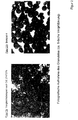
- Figure 2 a shows the organosilane preparation according to DE 27 47 277
- Example 1 and Figure 2 b the Organosilane preparation according to the invention according to Example 4. While the well-known organosilane preparations bake, show the organosilane preparations according to the invention in the optical assessment has clear advantages.
- the pearl size distribution is determined as follows:
- the sieves (standard sieves U.S. height 25 mm, diameter 200 mm, opening width 0.125 mm, 0.25 mm, 0.50 mm, 0.71 mm, 1.0 mm, 1.5 mm) and the collecting container are in the intended order, that is, from top to bottom decreasing opening width, put together. You weigh 100 g of the soot to be examined, with a suitable one Shovel is used. Under no circumstances should soot be allowed to run out be poured out of the container, since then a preselection of the Pearls would occur. After transferring the weighed Soot is placed on the top sieve and the stack into the screening machine (Ro-tap No. 704) used that a game of about 1.5 mm remains and the Sieves can thus rotate freely.
- the cover plate should with be provided with a cork stopper.
- the sieves are in the Machine attached and then for 1 minute - with the hammer in operation - shaken. Then you take the sieves one after the other and weighs them in each the amount of soot to the nearest 0.1 g.
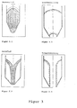
- a procedural silo dimensioning delivers the Inclination angle ⁇ of the funnel wall of an axially symmetrical (round base) or a flat (rectangular Base area) silos against the vertical and the Minimum diameter Dmin or the minimum width Bmin the discharge opening, if adhered to a trouble-free operation of the silo is guaranteed.
- the Jenike flowability index is common.
- the bulk solids strength fc alone is not sufficient to assess the flowability of a bulk material, since it depends on the hardening stress ⁇ 1.
- the one for process engineering silo dimensioning necessary parameters and the flowability index ffc can be verified using shear tests on a shaving device Jenike (measurement of the shear path / shear force curve at different normal stresses and the determination of the Friction between the container wall material and Bulk goods) (Peter Mertens: silo manual, Ernst + Sohn Verlag, Berlin 1988, pp. 50 - 52).
- the assessment of the conveying and abrasion behavior in pneumatic conveyors were based on Funding tests in a thin and a dense phase conveyor system.
- the material to be conveyed is used several times in the conveyor systems described below with the specified settings transported.
- the comparison of the Abrasion behavior was based on Particle size distributions of task and funded Good and a balance of the fine goods.
- the flight conveyor essentially consists of one Feed container with a blow-through lock Good delivery, a collecting container arranged above it, a nitrogen network connection for pressure generation, two Cyclones for separation and a downstream Filter.
- the delivery line has a length of 44 m, of which 6.3 m as a vertical riser and has seven 90 ° bends.
- the inner cable diameter is 56.3 mm.
- the Plant is operated with nitrogen. In order to do better Fines separation is only one of the two cyclones used.
- the conveyor length is 39 m, of which 5.7 m is a vertical riser.
- the line has four 90 ° bends and one 180 ° bend.
- the conveying gas nitrogen is fed in two partial flows (upper and lower air) via Laval nozzles.
- Tables 14 to 17 list the values for run D 90%, D 50% and D 10% of the run total distribution of the conveyed material and the starting material.
- Flight promotion attempt 1 Continuity Source material Conveying distance: 42 m Conveying distance: 132 m D 10% 890 990 900 D 50% 1270 1480 1670 D 90% 1760 2200 2060 Flight promotion attempt 2 Continuity Source material Conveying distance: 42 m Conveying distance: 132 m D 10% 810 - 720 D 50% 1210 - 1120 D 90% 1775 - 1670 Dense phase flow test 1 Continuity Source material Conveying distance: 39 m Conveyor distance: 195 m D 10% 790 1080 850 D 50% 1190 1510 1245 D 90% 1975 2095 1810 Dense phase flow test 2 Continuity Source material Conveying distance: 39 m Conveyor distance: 195 m D 10% 840 700 650 D 50% 1240 1110 1090 D 90% 1810 1610 1590
- the product of the invention can in dense and thin stream within the stated limits without problems and be promoted in a reliable manner. Flight as well Dense flow conveying up to a conveying gas speed of 28m / s do not cause a relevant increase in the Fine grain content.
- the material is available after flight promotion a path length of 132m or dense phase conveyance via a path length of 195 m as dust-free granules.
- the Conveyed goods have after pneumatic transport good bulk properties.
Landscapes
- Chemical & Material Sciences (AREA)
- Organic Chemistry (AREA)
- Health & Medical Sciences (AREA)
- Chemical Kinetics & Catalysis (AREA)
- Medicinal Chemistry (AREA)
- Polymers & Plastics (AREA)
- Compositions Of Macromolecular Compounds (AREA)
- Silicon Polymers (AREA)
- Silicon Compounds (AREA)
- Pigments, Carbon Blacks, Or Wood Stains (AREA)
- Processes Of Treating Macromolecular Substances (AREA)
- Paper (AREA)
- Silicates, Zeolites, And Molecular Sieves (AREA)
Abstract
Description
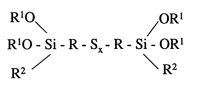
- R1
- einen einwertigen Alkylrest mit 1 bis 3 Kohlenstoffatomen
- R2
- einen einwertigen Alkyl- oder Alkoxyrest mit 1 bis 3 Kohlenstoffatomen
- R
- einen zweiwertigen Alkylrest mit 1 bis 5 Kohlenstoffatomen und
- x
- einen Wert von 2,0 bis 6,0
- Figur 1:
- Schematische Darstellung des Mischgranulators.
| Schüttdichte [g/l] | DBP [ml/100g] | CTAB [m2/gl | Jodzahl [mg/g] | Feuchte [%] | |
| N 330 | 77 | 122 | 86 | 93 | 0,5 |
| Beispiel | 1 | 2 | 3 | 4 | 5 | |
| N 330 | kg/h | 25 | 25 | 26,5 | 26,5 | 33 |
| Si 69 | kg/h | 26,4 | 26,4 | 26,5 | 26,5 | 36 |
| Silangehalt | Gew.-% | 51,4 | 51,4 | 50,0 | 50,0 | 52,2 |
| Düsenposition | 5 cm nach Einlauf des Rußpulvers | |||||
| Düse | mm | 1,3 | 1,3 | 1,3 | 1,3 | 1,3 |
| Düsendruck | bar | 4 | 1,5 | 1,5 | 0,8 | 1,5 |
| Mischer Drehzahl | UpM | 650 | 650 | 714 | 650 | 550 |
| Mischer Stromaufnahme | A | 15,5 -16,5 | 16,5 -17,5 | 16 -17,5 | 15,5 -17 | 15,5 -18 |
| Mischer Temperatur | °C | 100 | 100 | 100 | 100 | 100 |
| Endprodukt-Temperatur | °C | ca. 60 | ca. 60 | ca. 60 | ca. 60 |

| Beispiel | Optische Beurteilung |
| Beispiel 1 | Unterschiedliche Verperlung mit einigen Agglomeraten. Farbe dunkelgrau Sehr gutes Fließverhalten |
| Beispiel 2 | Wie bei Beispiel 1 |
| Beispiel 3 | Gleichmäßige Verperlung mit einigen Agglomeraten Farbe: dunkelgrau Sehr gutes Fließverhalten |
| Beispiel 4 | Gleichmäßige microperlartige Verperlung mit einigen Agglomeraten. Farbe: dunkelgrau Sehr gutes Fließverhalten |
| Beispiel 5 | Sehr grobes Material mit einigen Agglomeraten. Farbe: dunkelgrau Sehr gutes Fließverhalten |
| Schüttdichte | ASTM D1513 |
| DBP | ASTM D2414 |
| CTAB | ASTM D3765 |
| Jodzahl | ASTM D1510 |
| Feuchte | ASTM D1509 |
| Feinstanteil | ASTM D1508 |
| Flüchtige Anteile | ASTM D1509 |
| Schwefelgehalt | DIN 51400 |
| Momentanfließverhalten des Vergleichsbeispiels gemäß DE 27 47 277 | |||||||||
| Anscherspannung 2580 Pa | Anscherspannung 3850 Pa | Anscherspannung 7020 Pa | |||||||
| σ1 [Pa] | fc [Pa] | ffc | σ1 [Pa] | fc [Pa] | ffc | σ1 [Pa] | fc [Pa] | ffc | |
| Vergleichs beispiel DE 27 47 277 | 5310 | 1380 | 3,8 | 7879 | 1984 | 4,0 | 14270 | 2853 | 5,0 |
| Schüttgutfestigkeit in Abhängigkeit von der Lagerzeit für das Vergleichsbeispiel gemäß DE 27 47 277 | ||||
| Anscherspannung: 3850 Pa | ||||
| Schüttgutfestigkeit fc [Pa] | ||||
| Zeit [Tage] | 0 | 1 | 3 | 5 |
| Vergleichsbeispiel gemäß DE 27 47 277 | 1984 | 2220 | 3300 | 7730 |
| Mindestdurchmesser der Austragöffnung für ein angenommenes axialsymetrisches Silo mit einer Trichterwandneigung ax = 25° für das Vergleichsbeispiel DE 27 47 277 | ||||
| Mindestdurchmesser der Austragöffnung Dmin [mm] | ||||
| Zeit [Tage] | 0 | 1 | 3 | 5 |
| Vergleichsbeispiel gemäß DE 27 47 277 | 335 | 380 | 875 | 2640 |
| Momentanfließverhalten von Beispiel 5 | |||||||||
| Anscherspannung 2120 Pa | Anscherspannung 3560 Pa | Anscherspannung 6460 Pa | |||||||
| σ1 [Pa] | fc [Pa] | ffc | σ1 [Pa] | fc [Pa] | ffc | σ1 [Pa] | fc [Pa] | ffc | |
| Beispiel 5 | 5360 | 470 | 11 | 8880 | 820 | 11 | 16010 | 2095 | 7,6 |
| Schüttgutfestigkeit in Abhängigkeit von der Lagerzeit für Beispiel 5 | ||||
| Anscherspannung : 3560 Pa | ||||
| Schüttgutfestigkeit fc [Pa] | ||||
| Zeit [Tage] | 0 | 1 | 7 | 14 |
| Beispiel 5 | 470 | 640 | 640 | 640 |
| Mindestdurchmesser der Austragöffnung für ein angenommenes axialsymetrisches Silo mit einer Trichterwandneigung ax = 25° für Beispiel 5 | ||||
| Mindestdurchmesser der Austragöffnung Dmin [mm] | ||||
| Zeit [Tage] | 0 | 1 | 7 | 14 |
| Beispiel 5 | <30 | 30 | 30 | 30 |
| Flugförderung Beispiel 5 | ||
| Versuch 1 | Versuch 2 | |
| Gasmassenstrom [kg/h] | 200 | 300 |
| Volumenstrom [m3/h] | 166,7 | 250,0 |
| Druckverlust [mbar] | 225 | 315 |
| Einwaage [kg] | 49,6 | 50,8 |
| Zeit [min] | 3,58 | 2,5 |
| Massenstrom [kg/h] | 831 | 1219 |
| Beladung µ [kg Feststoff/kg Fördergas] | 4,2 | 4,1 |
| v Fördergas [m/s] | 18,8 | 28,2 |
| Dichte Gas [kg/m3] | 1,2 | 1,2 |
| Temperatur Gas [°C] | 20 | 20 |
| Gesamtförderstrecke [m] | 132 | 132 |
| Dichtstromförderung Versuch 1 | ||||||
| Oberluft | Unterluft | |||||
| Düse: | 10 | Düse | 45 | |||
| Vordruck stat: | 1 | bar | Vordruck stat: | 3 | bar | |
| Vordruck dyn.: | 1 | bar | Vordruck dyn.: | 2,5 | bar | |
| Zähler Anfang | 821,7 | Zähler Anfang | 1683,53 | |||
| Zähler Ende: | 821,7 | Zähler Ende: | 1684,1 | |||
| Zeit: | 3 | Min | 2,3 | |||
| Volumenstrom | 0,0 | m3/h | Volumenstrom | 11,4 | m3/h | |
| Gesamtvolumenstrom | 11,4 m3/h | |||||
| V gemessen | m3/h | V gemessen | 12,1 | m3/h | ||
| Förderdruck | 1,2 | bar | Förderdruck | 2 | bar | |
| Einwaage | 46 | kg | ||||
| Massenstrom | 920 | kg/h | ||||
| Beladung µ | 67,3 | kg Feststoff/kg Fördergas | ||||
| v Fördergas | 1,1 | m/s | ||||
| Dichte Gas | 1,2 | kg/m3 | ||||
| Temperatur Gas | 20 | °C | ||||
| Gesamtförderstrecke | 200 | m |
| Dichtstromförderung Versuch 2 | ||||||
| Oberluft | Unterluft | |||||
| Düse: | 45 | Düse: | 55 | |||
| Vordruck stat: | 2,8 | bar | Verdruck stat: | 3 | bar | |
| Vordruck dyn.: | 2,2 | bar | Vordruck dyn.: | 2,5 | bar | |
| Zähler Anfang: | 834,22 | Zähler Anfang | 1688,34 | |||
| Zähler Ende: | 824,6 | Zähler Ende | 1688,65 | |||
| Zeit: | 1,25 | Min | 1,25 | |||
| Volumenstrom | 18,2 | m3/h | Volumenstrom | 14,9 | m3/h | |
| Gesamtvolumenstrom | 33,1 m3/h | |||||
| V gemessen | m3/3 | V gemessen | m3/h | |||
| Förderdruck | 2,2 | Bar | Förderdruck | 2,5 | bar | |
| Einwaage | 51 | Kg | ||||
| Massenstrom | 2448 | Kg/h | ||||
| Beladung µ | 61,6 | KgFeststoff/kg Fördergas | ||||
| v Fördergas | 3,3 | m/s | ||||
| Dichte Gas | 1,2 | Kg/m3 | ||||
| Temperatur Gas | 20 | °C | ||||
| Gesamtförderstrecke | 200 | m |
| Flugförderung Versuch 1 | |||
| Durchgang | Ausgangsmaterial | Förderstrecke: 42 m | Förderstrecke: 132 m |
| D 10 % | 890 | 990 | 900 |
| D 50 % | 1270 | 1480 | 1670 |
| D 90 % | 1760 | 2200 | 2060 |
| Flugförderung Versuch 2 | |||
| Durchgang | Ausgangsmaterial | Förderstrecke: 42 m | Förderstrecke: 132 m |
| D 10 % | 810 | - | 720 |
| D 50 % | 1210 | - | 1120 |
| D 90 % | 1775 | - | 1670 |
| Dichtstromförderung Versuch 1 | |||
| Durchgang | Ausgangsmaterial | Förderstrecke: 39 m | Förderstrecke: 195 m |
| D 10 % | 790 | 1080 | 850 |
| D 50 % | 1190 | 1510 | 1245 |
| D 90 % | 1975 | 2095 | 1810 |
| Dichtstromförderung Versuch 2 | |||
| Durchgang | Ausgangsmaterial | Förderstrecke: 39 m | Förderstrecke: 195 m |
| D 10 % | 840 | 700 | 650 |
| D 50 % | 1240 | 1110 | 1090 |
| D 90 % | 1810 | 1610 | 1590 |
Claims (11)
- Granulatförmige Organosilan-Präparation, bestehend aus einem Gemisch aus einem oder mehreren Organosilanen und einem oder mehreren Füllstoffen, dadurch gekennzeichnet, daß sie einen Feinstanteil von kleiner 2% aufweist.
- Organosilan-Präparation nach Anspruch 1, dadurch gekennzeichnet, daß sie eine Perlfraktion von kleiner 0,125 mm von weniger als 2% aufweist.
- Organosilan-Präparation nach Anspruch 1 und 2, dadurch gekennzeichnet, daß der Silangehalt 1 bis 70 Gew.-% bezogen auf die granulatförmige Organosilan-Präparation beträgt.
- Organosilan-Präparation nach Anspruch 1 bis 3, dadurch gekennzeichnet, daß als Füllstoff Ruße oder Kieselsäuren eingesetzt werden.
- Verfahren zur Herstellung der Organosilan-Präparationen dadurch gekennzeichnet, daß man mindestens ein Organosilan mit einem Füllstoff vermischt und als Mischvorrichtung einen beheizbaren Mischgranulator verwendet.
- Verfahren zur Herstellung der Organosilan-Präparationen nach Anspruch 5, dadurch gekennzeichnet, daß man den Füllstoff mittels einer gravimetrischen Pulverdosierung zudosiert.
- Verfahren zur Herstellung von Organosilan-Präparationen nach Anspruch 5, dadurch gekennzeichnet, daß man das Silan volumetrisch oder gravimetrisch zudosiert.
- Verfahren zur Herstellung von Organosilan-Präparationen nach Anspruch 5, dadurch gekennzeichnet, daß man das Silan mittels einer oder mehreren Düsen an einer oder mehreren Position eindüst.
- Verfahren zur Herstellung von Organosilan-Präparationen nach Anspruch 5, dadurch gekennzeichnet, daß man bei einer Mischtemperatur von 40° bis 140°C vermischt.
- Verfahren zur Herstellung von Organosilan-Präparationen nach Anspruch 5, dadurch gekennzeichnet, daß man die Drehzahl des Mischgranulators in dem Bereich von 100 bis 1500 UpM variiert.
- Verwendung der granulatförmigen Organosilan-Präparation nach Anspruch 1, in vulkanisierbaren Kautschukmischungen.
Applications Claiming Priority (2)
| Application Number | Priority Date | Filing Date | Title |
|---|---|---|---|
| DE19955850 | 1999-11-20 | ||
| DE19955850A DE19955850A1 (de) | 1999-11-20 | 1999-11-20 | Granulatförmige Organosilan-Präparation, Verfahren zu ihrer Herstellung und ihre Verwendung |
Publications (3)
| Publication Number | Publication Date |
|---|---|
| EP1101802A2 true EP1101802A2 (de) | 2001-05-23 |
| EP1101802A3 EP1101802A3 (de) | 2002-07-31 |
| EP1101802B1 EP1101802B1 (de) | 2007-09-26 |
Family
ID=7929710
Family Applications (1)
| Application Number | Title | Priority Date | Filing Date |
|---|---|---|---|
| EP00124045A Expired - Lifetime EP1101802B1 (de) | 1999-11-20 | 2000-11-04 | Granulatförmige Organosilan-Präparation, Verfahren zu ihrer Herstellung und ihrer Verwendung |
Country Status (15)
| Country | Link |
|---|---|
| US (1) | US6410769B1 (de) |
| EP (1) | EP1101802B1 (de) |
| JP (1) | JP2001192507A (de) |
| KR (1) | KR100730905B1 (de) |
| CN (1) | CN1183191C (de) |
| AT (1) | ATE374229T1 (de) |
| BR (1) | BR0005498B1 (de) |
| CA (1) | CA2326544A1 (de) |
| DE (2) | DE19955850A1 (de) |
| ES (1) | ES2292399T3 (de) |
| ID (1) | ID28422A (de) |
| PL (1) | PL207925B1 (de) |
| TR (1) | TR200003413A3 (de) |
| TW (1) | TW538102B (de) |
| ZA (1) | ZA200006695B (de) |
Cited By (1)
| Publication number | Priority date | Publication date | Assignee | Title |
|---|---|---|---|---|
| EP1514892A1 (de) * | 2003-05-02 | 2005-03-16 | Degussa AG | Organosilankonzentrat |
Families Citing this family (2)
| Publication number | Priority date | Publication date | Assignee | Title |
|---|---|---|---|---|
| DE102013203651A1 (de) | 2013-03-04 | 2014-09-04 | Evonik Degussa Gmbh | Mercaptosilan-Polymer-Abmischung |
| JP6820002B2 (ja) * | 2016-12-09 | 2021-01-27 | 精工化学株式会社 | シランカップリング剤組成物及びゴム用配合剤 |
Family Cites Families (12)
| Publication number | Priority date | Publication date | Assignee | Title |
|---|---|---|---|---|
| DE1592861C3 (de) | 1966-09-28 | 1980-01-10 | Deutsche Gold- Und Silber-Scheideanstalt Vormals Roessler, 6000 Frankfurt | Verfahren zum Naßverperlen von Ruß mit weißen Füllstoffen und/oder Flüssigkeiten |
| US3997356A (en) * | 1971-08-17 | 1976-12-14 | Deutsche Gold- Und Silber-Scheideanstalt Vormals Roessler | Reinforcing additive |
| BE787691A (fr) * | 1971-08-17 | 1973-02-19 | Degussa | Composes organosiliciques contenant du soufre |
| DE2747277C2 (de) * | 1977-10-21 | 1982-06-09 | Degussa Ag, 6000 Frankfurt | Granulatförmige Organosilan-Präparation, deren Herstellung und Verwendung |
| DE4435311A1 (de) | 1994-10-01 | 1996-04-04 | Huels Silicone Gmbh | Verstärkungsadditive |
| JP3534464B2 (ja) * | 1994-12-22 | 2004-06-07 | 東ソー・シリカ株式会社 | 部分疎水性化沈降ケイ酸 |
| US5653794A (en) * | 1995-12-01 | 1997-08-05 | Scm Chemicals, Inc. | Silane treated inorganic pigments |
| DE19609619A1 (de) * | 1996-03-12 | 1997-09-18 | Degussa | Staubarme, gut dispergierbare Granulate auf der Basis von mit Organosiliciumverbindungen modifizierten silikatischen Füllstoffen |
| DE19613796A1 (de) * | 1996-04-04 | 1997-10-09 | Degussa | Ruß und Verfahren zu seiner Herstellung |
| DE19621462A1 (de) * | 1996-05-29 | 1997-12-04 | Degussa | Mischungen, bestehend aus feinteiligem Feldspat und Organosiliciumverbindungen, ihre Herstellung und Verwendung |
| DE19623198A1 (de) * | 1996-06-11 | 1997-12-18 | Degussa | Verfahren zur kontinuierlichen Trockengranulation von Pulverruß |
| US6962952B2 (en) * | 1997-04-30 | 2005-11-08 | The Yokohama Rubber Co., Ltd. | Process for production of modified carbon black for rubber reinforcement and process of production of rubber composition containing modified carbon black |
-
1999
- 1999-11-20 DE DE19955850A patent/DE19955850A1/de not_active Ceased
-
2000
- 2000-11-04 AT AT00124045T patent/ATE374229T1/de not_active IP Right Cessation
- 2000-11-04 EP EP00124045A patent/EP1101802B1/de not_active Expired - Lifetime
- 2000-11-04 DE DE50014675T patent/DE50014675D1/de not_active Expired - Lifetime
- 2000-11-04 ES ES00124045T patent/ES2292399T3/es not_active Expired - Lifetime
- 2000-11-13 TW TW089123994A patent/TW538102B/zh not_active IP Right Cessation
- 2000-11-14 ID IDP20000982D patent/ID28422A/id unknown
- 2000-11-16 CA CA002326544A patent/CA2326544A1/en not_active Abandoned
- 2000-11-16 ZA ZA200006695A patent/ZA200006695B/xx unknown
- 2000-11-17 PL PL343953A patent/PL207925B1/pl unknown
- 2000-11-17 TR TR2000/03413A patent/TR200003413A3/tr unknown
- 2000-11-18 KR KR1020000068706A patent/KR100730905B1/ko not_active Expired - Fee Related
- 2000-11-20 JP JP2000353583A patent/JP2001192507A/ja active Pending
- 2000-11-20 CN CNB001325175A patent/CN1183191C/zh not_active Expired - Lifetime
- 2000-11-20 US US09/715,038 patent/US6410769B1/en not_active Expired - Lifetime
- 2000-11-21 BR BRPI0005498-4A patent/BR0005498B1/pt not_active IP Right Cessation
Cited By (2)
| Publication number | Priority date | Publication date | Assignee | Title |
|---|---|---|---|---|
| EP1514892A1 (de) * | 2003-05-02 | 2005-03-16 | Degussa AG | Organosilankonzentrat |
| US7666933B2 (en) | 2003-05-02 | 2010-02-23 | Degussa Ag | Organosilane masterbatch |
Also Published As
| Publication number | Publication date |
|---|---|
| PL207925B1 (pl) | 2011-02-28 |
| PL343953A1 (en) | 2001-05-21 |
| BR0005498A (pt) | 2001-07-24 |
| ATE374229T1 (de) | 2007-10-15 |
| TW538102B (en) | 2003-06-21 |
| KR100730905B1 (ko) | 2007-06-22 |
| ZA200006695B (en) | 2001-08-10 |
| TR200003413A2 (tr) | 2001-06-21 |
| JP2001192507A (ja) | 2001-07-17 |
| ID28422A (id) | 2001-05-24 |
| DE19955850A1 (de) | 2001-06-07 |
| EP1101802A3 (de) | 2002-07-31 |
| DE50014675D1 (de) | 2007-11-08 |
| US6410769B1 (en) | 2002-06-25 |
| CN1183191C (zh) | 2005-01-05 |
| EP1101802B1 (de) | 2007-09-26 |
| CN1296987A (zh) | 2001-05-30 |
| TR200003413A3 (tr) | 2001-06-21 |
| ES2292399T3 (es) | 2008-03-16 |
| KR20010051796A (ko) | 2001-06-25 |
| CA2326544A1 (en) | 2001-05-20 |
| BR0005498B1 (pt) | 2011-05-17 |
Similar Documents
| Publication | Publication Date | Title |
|---|---|---|
| DE2747277C2 (de) | Granulatförmige Organosilan-Präparation, deren Herstellung und Verwendung | |
| EP0802242B1 (de) | Verfahren zur Herstellung von Brikettier- und Pressgranulaten | |
| DE69203643T2 (de) | Trockenzermahlung. | |
| EP0373426A2 (de) | Anorganische Pigmente mit Polyorganosiloxanbeschichtung | |
| EP0101088B1 (de) | Verfahren und Vorrichtung zum Reinigen von Pyrolysegasen | |
| EP2362885B1 (de) | Russgranulat, verfahren zur herstellung von russgranulat und dessen verwendung | |
| EP1845137A2 (de) | Verfahren zur Herstellung von Pigmentgranulaten und deren Verwendung | |
| DE2910991A1 (de) | Verfahren zur herstellung von mischgranulat aus russ und hellem fuellstoff | |
| EP0814133A1 (de) | Verfahren zur kontinuierlichen Trockengranulation von Pulverruss | |
| DE19816972A1 (de) | Pulverförmige, modifizierte Füllstoffe enthaltende Kautschukpulver, Verfahren zu ihrer Herstellung und Verwendung | |
| EP0924268B1 (de) | Perlruss und Verfahren zu seiner Herstellung | |
| EP1101802B1 (de) | Granulatförmige Organosilan-Präparation, Verfahren zu ihrer Herstellung und ihrer Verwendung | |
| EP1241133A2 (de) | Inhomogene Kieselsäuren für Elastomerenmischungen | |
| EP1215249A1 (de) | Perlruss | |
| EP1813573A1 (de) | Verfahren zur Herstellung von Gummimischungen | |
| DE19904657B4 (de) | Verfahren zur Herstellung von Vollwaschmitteln und Vollwaschmittelkomponenten | |
| DE3530415C2 (de) | ||
| DE19846744A1 (de) | Verfahren zur Modifizierung der Oberfläche eines Tonmineralgemisches und nach diesem Verfahren hergestellte Stoffe | |
| DE102014010036A1 (de) | Verfahren zur Herstellung eines Gummi-Werkstoffes | |
| DE19639856C2 (de) | Verfahren und Vorrichtung zum Fördern von Feinstoffen als Zuschlag in körnigen Produkten | |
| DE2216861A1 (de) | Vorrichtung und verfahren zum pelletisieren von anorganischen pigmenten | |
| DE2355570C3 (de) | Verfahren zur Herstellung von freifließenden, gut dispergierbaren Kieselsäureperlen mit niedriger Einzelperlhärte | |
| DE4014229A1 (de) | Dosierung und transport fluidisierbarer gueter | |
| EP1153862A1 (de) | Vorrichtung und Verfahren zur Feststoffdosierung und pneumatischen Förderung | |
| DE3637322A1 (de) | Aggregate zur vorbenetzung und/oder dispergierung auf dem gebiet der herstellung von pastoesen und fluessigen druckfarben |
Legal Events
| Date | Code | Title | Description |
|---|---|---|---|
| PUAI | Public reference made under article 153(3) epc to a published international application that has entered the european phase |
Free format text: ORIGINAL CODE: 0009012 |
|
| 17P | Request for examination filed |
Effective date: 20001104 |
|
| AK | Designated contracting states |
Kind code of ref document: A2 Designated state(s): AT BE CH CY DE DK ES FI FR GB GR IE IT LI LU MC NL PT SE TR |
|
| AX | Request for extension of the european patent |
Free format text: AL;LT;LV;MK;RO;SI |
|
| RIN1 | Information on inventor provided before grant (corrected) |
Inventor name: PITSCH, HOLGER Inventor name: EICHENAUER, KURT Inventor name: KOPIET, JAN Inventor name: KRIESCH, HELMUT Inventor name: VOGLER, CONNY, DR. Inventor name: KLOSE, MICHAEL |
|
| PUAL | Search report despatched |
Free format text: ORIGINAL CODE: 0009013 |
|
| RIC1 | Information provided on ipc code assigned before grant |
Free format text: 7C 09C 1/30 A, 7C 07F 7/18 B, 7C 08K 9/06 B, 7C 08K 9/12 B, 7C 08L 21/00 B, 7C 09C 1/56 B |
|
| AK | Designated contracting states |
Kind code of ref document: A3 Designated state(s): AT BE CH CY DE DK ES FI FR GB GR IE IT LI LU MC NL PT SE TR |
|
| AX | Request for extension of the european patent |
Free format text: AL;LT;LV;MK;RO;SI |
|
| AKX | Designation fees paid |
Designated state(s): AT BE CH CY DE DK ES FI FR GB GR IE IT LI LU MC NL PT SE TR |
|
| RAP1 | Party data changed (applicant data changed or rights of an application transferred) |
Owner name: DEGUSSA GMBH |
|
| GRAP | Despatch of communication of intention to grant a patent |
Free format text: ORIGINAL CODE: EPIDOSNIGR1 |
|
| GRAS | Grant fee paid |
Free format text: ORIGINAL CODE: EPIDOSNIGR3 |
|
| GRAA | (expected) grant |
Free format text: ORIGINAL CODE: 0009210 |
|
| AK | Designated contracting states |
Kind code of ref document: B1 Designated state(s): AT BE CH CY DE DK ES FI FR GB GR IE IT LI LU MC NL PT SE TR |
|
| REG | Reference to a national code |
Ref country code: GB Ref legal event code: FG4D Free format text: NOT ENGLISH |
|
| REG | Reference to a national code |
Ref country code: CH Ref legal event code: EP |
|
| RAP2 | Party data changed (patent owner data changed or rights of a patent transferred) |
Owner name: EVONIK DEGUSSA GMBH |
|
| REF | Corresponds to: |
Ref document number: 50014675 Country of ref document: DE Date of ref document: 20071108 Kind code of ref document: P |
|
| REG | Reference to a national code |
Ref country code: IE Ref legal event code: FG4D Free format text: LANGUAGE OF EP DOCUMENT: GERMAN |
|
| BECN | Be: change of holder's name |
Owner name: EVONIK DEGUSSA G.M.B.H. Effective date: 20070926 |
|
| GBT | Gb: translation of ep patent filed (gb section 77(6)(a)/1977) |
Effective date: 20071211 |
|
| NLT2 | Nl: modifications (of names), taken from the european patent patent bulletin |
Owner name: EVONIK DEGUSSA GMBH Effective date: 20071107 |
|
| PG25 | Lapsed in a contracting state [announced via postgrant information from national office to epo] |
Ref country code: FI Free format text: LAPSE BECAUSE OF FAILURE TO SUBMIT A TRANSLATION OF THE DESCRIPTION OR TO PAY THE FEE WITHIN THE PRESCRIBED TIME-LIMIT Effective date: 20070926 |
|
| REG | Reference to a national code |
Ref country code: ES Ref legal event code: FG2A Ref document number: 2292399 Country of ref document: ES Kind code of ref document: T3 |
|
| ET | Fr: translation filed | ||
| PG25 | Lapsed in a contracting state [announced via postgrant information from national office to epo] |
Ref country code: GR Free format text: LAPSE BECAUSE OF FAILURE TO SUBMIT A TRANSLATION OF THE DESCRIPTION OR TO PAY THE FEE WITHIN THE PRESCRIBED TIME-LIMIT Effective date: 20071227 |
|
| REG | Reference to a national code |
Ref country code: IE Ref legal event code: FD4D |
|
| PG25 | Lapsed in a contracting state [announced via postgrant information from national office to epo] |
Ref country code: PT Free format text: LAPSE BECAUSE OF FAILURE TO SUBMIT A TRANSLATION OF THE DESCRIPTION OR TO PAY THE FEE WITHIN THE PRESCRIBED TIME-LIMIT Effective date: 20080226 |
|
| PG25 | Lapsed in a contracting state [announced via postgrant information from national office to epo] |
Ref country code: MC Free format text: LAPSE BECAUSE OF NON-PAYMENT OF DUE FEES Effective date: 20071130 Ref country code: SE Free format text: LAPSE BECAUSE OF FAILURE TO SUBMIT A TRANSLATION OF THE DESCRIPTION OR TO PAY THE FEE WITHIN THE PRESCRIBED TIME-LIMIT Effective date: 20071226 |
|
| PG25 | Lapsed in a contracting state [announced via postgrant information from national office to epo] |
Ref country code: CH Free format text: LAPSE BECAUSE OF NON-PAYMENT OF DUE FEES Effective date: 20071130 Ref country code: DK Free format text: LAPSE BECAUSE OF FAILURE TO SUBMIT A TRANSLATION OF THE DESCRIPTION OR TO PAY THE FEE WITHIN THE PRESCRIBED TIME-LIMIT Effective date: 20070926 Ref country code: LI Free format text: LAPSE BECAUSE OF NON-PAYMENT OF DUE FEES Effective date: 20071130 |
|
| REG | Reference to a national code |
Ref country code: CH Ref legal event code: PL |
|
| PLBE | No opposition filed within time limit |
Free format text: ORIGINAL CODE: 0009261 |
|
| STAA | Information on the status of an ep patent application or granted ep patent |
Free format text: STATUS: NO OPPOSITION FILED WITHIN TIME LIMIT |
|
| RAP2 | Party data changed (patent owner data changed or rights of a patent transferred) |
Owner name: EVONIK DEGUSSA GMBH |
|
| 26N | No opposition filed |
Effective date: 20080627 |
|
| NLT1 | Nl: modifications of names registered in virtue of documents presented to the patent office pursuant to art. 16 a, paragraph 1 |
Owner name: EVONIK DEGUSSA GMBH |
|
| NLT2 | Nl: modifications (of names), taken from the european patent patent bulletin |
Owner name: EVONIK DEGUSSA GMBH Effective date: 20080806 |
|
| PG25 | Lapsed in a contracting state [announced via postgrant information from national office to epo] |
Ref country code: IE Free format text: LAPSE BECAUSE OF FAILURE TO SUBMIT A TRANSLATION OF THE DESCRIPTION OR TO PAY THE FEE WITHIN THE PRESCRIBED TIME-LIMIT Effective date: 20070926 |
|
| PG25 | Lapsed in a contracting state [announced via postgrant information from national office to epo] |
Ref country code: AT Free format text: LAPSE BECAUSE OF NON-PAYMENT OF DUE FEES Effective date: 20071104 |
|
| PG25 | Lapsed in a contracting state [announced via postgrant information from national office to epo] |
Ref country code: CY Free format text: LAPSE BECAUSE OF FAILURE TO SUBMIT A TRANSLATION OF THE DESCRIPTION OR TO PAY THE FEE WITHIN THE PRESCRIBED TIME-LIMIT Effective date: 20070926 |
|
| PG25 | Lapsed in a contracting state [announced via postgrant information from national office to epo] |
Ref country code: LU Free format text: LAPSE BECAUSE OF NON-PAYMENT OF DUE FEES Effective date: 20071104 |
|
| PG25 | Lapsed in a contracting state [announced via postgrant information from national office to epo] |
Ref country code: TR Free format text: LAPSE BECAUSE OF FAILURE TO SUBMIT A TRANSLATION OF THE DESCRIPTION OR TO PAY THE FEE WITHIN THE PRESCRIBED TIME-LIMIT Effective date: 20070926 |
|
| REG | Reference to a national code |
Ref country code: FR Ref legal event code: CA |
|
| PG25 | Lapsed in a contracting state [announced via postgrant information from national office to epo] |
Ref country code: IT Free format text: LAPSE BECAUSE OF NON-PAYMENT OF DUE FEES Effective date: 20071130 |
|
| PGFP | Annual fee paid to national office [announced via postgrant information from national office to epo] |
Ref country code: NL Payment date: 20111124 Year of fee payment: 12 |
|
| PGFP | Annual fee paid to national office [announced via postgrant information from national office to epo] |
Ref country code: BE Payment date: 20111110 Year of fee payment: 12 |
|
| BERE | Be: lapsed |
Owner name: EVONIK DEGUSSA G.M.B.H. Effective date: 20121130 |
|
| REG | Reference to a national code |
Ref country code: NL Ref legal event code: V1 Effective date: 20130601 |
|
| PG25 | Lapsed in a contracting state [announced via postgrant information from national office to epo] |
Ref country code: NL Free format text: LAPSE BECAUSE OF NON-PAYMENT OF DUE FEES Effective date: 20130601 Ref country code: BE Free format text: LAPSE BECAUSE OF NON-PAYMENT OF DUE FEES Effective date: 20121130 |
|
| PGFP | Annual fee paid to national office [announced via postgrant information from national office to epo] |
Ref country code: GB Payment date: 20131120 Year of fee payment: 14 |
|
| PGFP | Annual fee paid to national office [announced via postgrant information from national office to epo] |
Ref country code: ES Payment date: 20131128 Year of fee payment: 14 |
|
| GBPC | Gb: european patent ceased through non-payment of renewal fee |
Effective date: 20141104 |
|
| PG25 | Lapsed in a contracting state [announced via postgrant information from national office to epo] |
Ref country code: GB Free format text: LAPSE BECAUSE OF NON-PAYMENT OF DUE FEES Effective date: 20141104 |
|
| REG | Reference to a national code |
Ref country code: FR Ref legal event code: PLFP Year of fee payment: 16 |
|
| REG | Reference to a national code |
Ref country code: ES Ref legal event code: FD2A Effective date: 20151229 |
|
| PG25 | Lapsed in a contracting state [announced via postgrant information from national office to epo] |
Ref country code: ES Free format text: LAPSE BECAUSE OF NON-PAYMENT OF DUE FEES Effective date: 20141105 |
|
| REG | Reference to a national code |
Ref country code: FR Ref legal event code: PLFP Year of fee payment: 17 |
|
| REG | Reference to a national code |
Ref country code: FR Ref legal event code: PLFP Year of fee payment: 18 |
|
| REG | Reference to a national code |
Ref country code: DE Ref legal event code: R081 Ref document number: 50014675 Country of ref document: DE Owner name: EVONIK OPERATIONS GMBH, DE Free format text: FORMER OWNER: EVONIK DEGUSSA GMBH, 40474 DUESSELDORF, DE |
|
| PGFP | Annual fee paid to national office [announced via postgrant information from national office to epo] |
Ref country code: DE Payment date: 20191121 Year of fee payment: 20 |
|
| PGFP | Annual fee paid to national office [announced via postgrant information from national office to epo] |
Ref country code: FR Payment date: 20191120 Year of fee payment: 20 |