EP1101611A1 - Device for exchangeably supporting and positioning printing cylinders of an offset printing press - Google Patents
Device for exchangeably supporting and positioning printing cylinders of an offset printing press Download PDFInfo
- Publication number
- EP1101611A1 EP1101611A1 EP00204070A EP00204070A EP1101611A1 EP 1101611 A1 EP1101611 A1 EP 1101611A1 EP 00204070 A EP00204070 A EP 00204070A EP 00204070 A EP00204070 A EP 00204070A EP 1101611 A1 EP1101611 A1 EP 1101611A1
- Authority
- EP
- European Patent Office
- Prior art keywords
- printing
- cylinders
- cylinder
- bearing arm
- supporting
- Prior art date
- Legal status (The legal status is an assumption and is not a legal conclusion. Google has not performed a legal analysis and makes no representation as to the accuracy of the status listed.)
- Granted
Links
Images


Classifications
-
- B—PERFORMING OPERATIONS; TRANSPORTING
- B41—PRINTING; LINING MACHINES; TYPEWRITERS; STAMPS
- B41F—PRINTING MACHINES OR PRESSES
- B41F13/00—Common details of rotary presses or machines
- B41F13/44—Arrangements to accommodate interchangeable cylinders of different sizes to enable machine to print on areas of different sizes
Definitions
- the invention relates to a device for use in an offset printing press for supporting and positioning of printing cylinders of the printing press exchangeably therein.
- Such a format assembly is composed of a housing in which the printing cylinders belonging to a particular format are accommodated in a fixed manner, and in the case of which provision is also made for a gear wheel transmission between the successive printing cylinders, means for enabling the displacement of one or more cylinders axially, and further adjusting means.
- These format assemblies have to be placed in a printing tower by means of a lift truck, after which the format assembly is fitted in the correct place in the printing tower and is locked therein, which operation can be carried out manually or by means of a pneumatic system fitted in the printing tower.
- a device according to the preamble of claim 1 is known from US-A-3 611 924, which shows an offset printing press wherein the image printing cylinder and transfer printing cylinder are changeably supported per se to permit the use of cylinders of different diameters for printing sheets of different length.
- the transfer printing cylinder is mounted on a pivoted bearing arm that can be rotated toward and away from the image printing cylinder and from an impression printing cylinder. After the transfer printing cylinder has been rotated away, the image printing cylinder can be removed via a horizontal slot.
- An adjustable eccentric bearing is provided for the transfer printing cylinder to be able to adjust it with respect to the other cylinders.
- a disadvantage with this known device is that it is relatively complex and expensive, and that its printing quality leaves to be desired.
- the adjusting of the eccentric bearing is time-consuming and must be performed each time after a new format of cylinders is placed. It frequently occurs that the transfer printing cylinder lies with different amounts of pressure against both other cylinders, leading to local enlargements or reductions of image dots transferred to the transfer printing cylinder and/or printed on the sheets. Printing on sheets with different thickness, has the same disadvantage of having to adjust the eccentric bearing, and also frequently leads to distortions of printed images.
- the axes of the several cylinders can not be brought in line with respect to each other for both large and small formats of cylinders.
- the supporting means for the cylinders must be relatively strong, and also a deterioration of printed images occurs, for example if small irregularities are present on one of the cylinders.
- a large rotation of the pivoted arm with transfer printing cylinder has to be made. Should only an image carrier plate on the image printing cylinder have to be changed, then this plate is barely accessible.
- the object of the invention is to overcome the above mentioned disadvantages, and more in particular to provide a simple and user friendly device with which only the format-dependent cylinders per se have to be changed while the necessary means for permitting correct positioning of the cylinders relative to each other are accommodated in the printing tower, and with which a good image printing quality can be achieved.
- the device comprises first and second bearing arms with supporting elements for permitting the accommodation in an exchangeable manner of at least two of the printing cylinders, and first and second actuating means for rotating of the first and second bearing arms respectively for positioning the at least two printing cylinders. This ensures that when there is a changeover to a different format only the format-dependent cylinders per se need to be changed. The cylinders are subsequently placed in the correct position relative to each other by the actuating means and bearing arms.
- the actuating means being able to rotate the bearing arms and supporting elements through a predetermined angle.
- the invention has the advantage that the mutual pressures between the cylinders can accurately and easily be adjusted by minor rotations of the bearing arms with respect to each other, making it possible to avoid distortions of images printed. Also different thickness in substrate to be printed is no longer a problem.
- By means of a suitable mutual adjustment of the positions of the bearing arms it is possible to each time have the cylinders approximately lying in line for different sets of formats. This also leads to an improved image quality, and makes it possible to construct the bearing arms, positioning elements, etc. somewhat less strong.
- Each of the cylinders is readily accessible, even when only an image plate or a compressible transfer layer has to be changed.
- Each of the cylinders supported by a bearing arm is preferably supported by bearing arms placed on both sides, the actuating means preferably also acting upon both bearing arms. This latter situation is preferred, since the cylinders can then not only be positioned always exactly parallel relative to each other, but can also be held securely in that position during operation. Also the actuating means for each bearing arm, preferably can be actuated separately. Thus, for example, one of the bearing arms can be loosened from the cylinder, then be rotated up or downwardly, after which the cylinder can be removed from the other bearing arm by taking it out sideways in the direction of the cylinder axis.
- a further development provides for the first actuating means to be rotatably connected to a fixed point and the first bearing arm, and for one or more further actuating means to be rotatably connected to the first bearing arm and a further bearing arm.
- a possible embodiment of this is to have the first actuating means acting upon a bearing arm of the transfer printing cylinder and two further actuating means acting upon a bearing arm of the transfer printing cylinder and upon a bearing arm of the image printing cylinder and the impression printing cylinder, respectively.
- the advantage obtained by this is that the positioning of the cylinders is less dependent upon one margin of error.
- a possible further variant of this is to place one of the cylinders, for example the image printing cylinder, in a fixed position and to provide the other cylinders on bearing arms co-operating with each other, that is to say the first actuating means actuable relative to a fixed point, while the second actuating means are actuable relative to the rotatable first bearing arm.
- the construction is very simple.
- Means for axially moving the image printing cylinder can advantageously be provided onto fixed supporting elements.
- inking mechanisms are already adjustably mounted, making it possible for several formats of image printing cylinders to be placed against them.
- the means for permitting a bearing arm to rotate through a predetermined angle comprise at least one adjustable distance device.
- Such an adjustable distance device can act near the end of the bearing arm, where a supporting element for a cylinder may also be situated.
- the adjustable distance device can be, for example, a screw spindle, a hydraulic cylinder or a gear rack system.
- a screw spindle has the advantage that it is rigid, cheap, and that its position is accurately computable, making it possible to adjust the relative positions of the cylinders based on position of the spindle, instead of based on pressure differences coming from contact between the cylinders.
- a hydraulic cylinder has the advantage that it is easily protectable against overpressure leading to damages or injuries.
- the drive of a screw spindle can be achieved by, for example, an electric motor, a reduction gearbox fitted between the motor and the driven part of the spindle ensuring that the desired torque is supplied and the driven part can always be moved over a minimum distance.
- a detection device to be connected to the drive for the driven element or to the driven element on the screw spindle, for detection of the angle of rotation of the drive shaft or the driven element on the screw spindle. Measuring or determining the angle of rotation ensures that the movement of the driven element along the spindle is known, and consequently so is the rotation of the bearing arm, and therefore also the new position of a supporting element.
- the device according to the invention in order to avoid complicated transmission constructions or having to change gear wheels for the changing positions of the printing cylinder for differing formats, provision is made for at least two of the printing cylinders to have their own drive for the purpose of rotation about their own axes.
- the drives are directly linked to the control system of the printing press, which makes it possible to synchronize the printing cylinders in a printing tower and also successive printing towers with each other in a simple manner.
- the drive of the impression cylinder by connecting the latter by means of, for example, a toothed belt transmission to the drive for the rollers of the inking train in the printing press or module thereof.
- the speed of the drive obtained in this way is sufficiently constant for the impression cylinder.
- the supporting elements for the printing cylinders can be composed of cones which are situated on either side of a printing cylinder and by axial displacement can be taken into and out of engagement with a printing cylinder.
- a through-running mandrel can be used as the supporting element, over which mandrel the cylinder can be pushed and on which it can be clamped by means of a mechanical, electrical or pneumatic clamping device.
- This has the advantage that the printing cylinders can be taken into and out of the printing tower in the axial direction, and thus at the side of the printing tower, and that manoeuvring between successive printing towers is not necessary.
- An additional advantage is that the weight of the cylinders can be lower than that of the printing cylinders that have to be wedged between two cones. If light materials are then also used for the manufacture of the printing cylinders, it is even possible to change over the cylinders by hand without aids.
- the device comprises a printing assembly having three printing cylinders, namely an image printing cylinder 1, a transfer printing cylinder 2 and an impression printing cylinder 3.
- the image printing cylinder 1 is supported in a fixed position with respect to a U-shaped supporting construction 4.
- the transfer printing cylinder 2 is supported on both ends between supporting elements 5.
- the impression printing cylinder 3 is supported on both ends between supporting elements 6.
- Each supporting element 5 is provided on a first bearing arm 8.
- Each supporting element 6 is provided on a second bearing arm 9.
- Each bearing arm 8, 9 is rotatable about an axis 10.
- the first bearing arm 8 is connected to first actuating means 12 for rotating the bearing arm 8 and supporting element 5 through predetermined angles around the axis 10.
- the second bearing arm 9 is connected to second actuating means 13 for rotating the bearing arm 9 and supporting element 6 through predetermined angles with respect to the axis 10.
- the second actuating means 13 are connected to the first bearing arm 8, causing the second actuating means 13 to move along with a rotation of the first bearing arm 8 if the first actuating means 12 are actuated.
- Both the first and second actuating means 12, 13 comprise an adjustable distance device, which in the embodiment shown is formed by a screw spindle.
- the component parts of the screw spindle of the first actuating means 12 are pivotably connected to the bearing arm 8 and to a fixed point 15 on the supporting construction 4.
- a drive 16 is provided for accurately rotating the screw spindle, resulting in an upward or downward movement of a nut element 17 connected pivotably to the first bearing arm 8.
- Component parts of the second actuating means 13 comprise a drive 18 pivotably connected to the first bearing arm 8 for driving the screw spindle, resulting in an upward or downward movement of a nut element 19 pivotably connected to the second bearing arm 9.
- the side walls of the supporting construction 4 are each provided with openings 20, 21.
- the openings 20, 21 make it possible for the bearing arms 8, 9 to shift the supporting elements 5, 6 mounted thereon, together with the printing cylinders 2, 3 supported between them, to other desired positions with respect to the image printing cylinder 1.
- a suitable actuation of the actuating means 12, 13 makes it possible to accurately position the printing cylinders 1-3 with respect to each other such that the pressure on the contact area between the image printing cylinder 1 and transfer printing cylinder 2 is approximately equal to the pressure on the contact area between the transfer printing cylinder 2 and the impression printing cylinder 3. This makes it possible to achieve a very good printing quality for sheets to be printed which are guided between the transfer printing cylinder 2 and the impression cylinder 3, even when substrate having different thickness is being used.
- the image printing cylinder 1 is provided with ink from an inking mechanism (not shown) positioned above the image printing cylinder 1.
- the inking mechanism is movably supported with respect to the image printing cylinder 1 in order to be able to ink different formats of image printing cylinders.
- Figs. 5 and 6 show embodiments greatly similar to the embodiments shown in figs. 1-4, with the difference that first and second bearing arms 51, 52 are each rotatable about their own axis 53, 54 respectively.
- first actuating means 55 for the first bearing arm 51 are indirectly connected to second actuating means 56 for the second bearing arm 52.
- the actuating means may not be interconnected.
- Fig. 6 shows the device supporting a larger format of printing cylinders 58, 59.
- the construction according to the invention makes it possible for the cylinders supported by their supporting elements to have their axes 60, 61, 62 lying approximately in line with respect to each other for both small and large format printing cylinders. With approximately in line here is meant the three axes 60, 61, 62 of the printing cylinders enclosing an angle in the range of 165-195°.
- the bearing arms 74, 75, 76 are rotatable about the respective fixed centres of rotation 77, 78, 79.
- Spindle 82 is fitted on a fixed centre of rotation 87 and is further connected to a pivot point 90 provided on bearing arm 75, spindle 80 is connected by way of pivot point 86 and fixing plate 86' to bearing arm 75, and by way of pivot point 89 and fixing arm 92 to bearing arm 74, and spindle 81 is connected by way of pivot point 88 and fixing arm 93 to bearing arm 75 and by way of pivot point 91 and fixing arm 94 to bearing arm 76.
- the spindles are driven by motors 95, 96, 97, which act upon them by means of a toothed belt.
- pulse generators 98, 99, 100 Connected to the driven spindles are pulse generators 98, 99, 100, which indicate precisely the angular displacement.
- Such a pulse generator is, for example, subdivided into 1,024 steps per full revolution, an absolute pulse being generated after the passing through of each step. The position of the cylinders is in fact determined by these pulse generators.
- the fig. further shows the drive motors 101, 102, 103 for the respective cylinders 71, 72, 73 and the motors 104, 105, which are fitted on the bearing arms 74, 75 and by means of toothed belts act upon the means for permitting axial adjustment of the supporting elements provided in the bearing arms.
- the axial movement of the supporting elements serves to wedge the printing cylinder, and to permit axial movement of the printing cylinder.
- the impression cylinder 73 is fitted immovably between the bearing arms.
- the positioning means of the bearing arms For bringing the impression cylinder up to pressure and releasing it from pressure, use is made of the positioning means of the bearing arms, so that the usual eccentrics for the impression cylinders can be dispensed with here.
- Fig. 8 shows a section through the bearing arms 74, 74' with drive motor 101 and supporting elements 106, 107.
- the supporting elements project through plate parts I and II of a frame and on the ends are provided with cones 108, 109, which are designed to fall into complementary parts of a cylinder and to wedge the cylinder.
- a register pin can also be fitted on one of the cones, being designed to fall into a slot of the cylinder, so that the cylinder always assumes a known position relative to the drive.
- the supporting elements 106, 107 can be moved in the axial direction, both in opposite directions, in order to wedge a cylinder or undo the wedging, and in the same direction, in order to permit axial movement of the cylinder.
- One of these motors 104 is shown in fig. 1.
- a gear wheel can also be used, which gear wheel acts upon gear wheels of a set of spindles 110, 111 or 112, 113.
- the drive motor 101 is connected by way of a direct transmission 118 to a shaft part 119 of the supporting element 106.
- fig. 9 shows a section of a possible supporting element which is substantially composed of a through-running mandrel 137, over which a printing cylinder 131 is pushed and clamped there with the aid of a clamping device 138.
- the clamping device 138 is supported in a part 139 of a housing which is fitted in a printing tower, and which can be removed or folded away together with the clamping device 138, with the result that sufficient space is produced to permit removal of a cylinder from the mandrel 137 or sliding of a cylinder onto the mandrel in the axial direction.
- drive motor 101 is connected by way of a spline shaft 141 to the shaft 142 of the mandrel 137, provision further being made for a drive mechanism 140 for permitting adjustment of the mandrel 137 in the axial direction.
- a spline shaft it is also possible, for example, to provide an axially adjustable coupling or a combination of two fixed gear wheels.
- a printing assembly having four printing cylinders may be provided for double sided printing of sheets, that is to say two image printing cylinders and two transfer printing cylinders.
- this supporting elements for at least three of the cylinders are provided on first, second and third bearing arms each rotatable about an axis, the positioning means comprising first, second and third actuating means for rotating each respective bearing arm and supporting element through predetermined angles.
- the actuating means may also be formed by a worm-gear mechanism connected to the bearing arm.
- bearing arms on both sides of the printing cylinders it is also possible to provide bearing arms on only one side of the printing cylinders.
- the device according to the invention makes it possible to provide for a quick and easy adjustment of an offset printing press for printing different formats of substrate, and/or for printing different substrate thickness.
- the at least two sets of bearing arms make it possible to accurately position the printing cylinders with respect to each other, resulting in a superb printing quality.
Abstract
Description
- The invention relates to a device for use in an offset printing press for supporting and positioning of printing cylinders of the printing press exchangeably therein.
- For the resetting of an offset printing press for variable sizes to another format it is known to exchange a printing assembly or even a format assembly in its entirety per printing tower. Such a format assembly is composed of a housing in which the printing cylinders belonging to a particular format are accommodated in a fixed manner, and in the case of which provision is also made for a gear wheel transmission between the successive printing cylinders, means for enabling the displacement of one or more cylinders axially, and further adjusting means. These format assemblies have to be placed in a printing tower by means of a lift truck, after which the format assembly is fitted in the correct place in the printing tower and is locked therein, which operation can be carried out manually or by means of a pneumatic system fitted in the printing tower.
- If a number of different formats have to be available for a printing press with only a minimum number of successive printing towers, it will be clear that already at that stage the number of format assemblies required very soon mounts up. The difference between the format assemblies is substantially the diameter of the format-dependent printing cylinders and that of the corresponding drive gears; the housing and the further adjusting means fitted therein are always virtually the same.
- A device according to the preamble of
claim 1 is known from US-A-3 611 924, which shows an offset printing press wherein the image printing cylinder and transfer printing cylinder are changeably supported per se to permit the use of cylinders of different diameters for printing sheets of different length. The transfer printing cylinder is mounted on a pivoted bearing arm that can be rotated toward and away from the image printing cylinder and from an impression printing cylinder. After the transfer printing cylinder has been rotated away, the image printing cylinder can be removed via a horizontal slot. An adjustable eccentric bearing is provided for the transfer printing cylinder to be able to adjust it with respect to the other cylinders. - A disadvantage with this known device is that it is relatively complex and expensive, and that its printing quality leaves to be desired. The adjusting of the eccentric bearing is time-consuming and must be performed each time after a new format of cylinders is placed. It frequently occurs that the transfer printing cylinder lies with different amounts of pressure against both other cylinders, leading to local enlargements or reductions of image dots transferred to the transfer printing cylinder and/or printed on the sheets. Printing on sheets with different thickness, has the same disadvantage of having to adjust the eccentric bearing, and also frequently leads to distortions of printed images. Furthermore, the axes of the several cylinders can not be brought in line with respect to each other for both large and small formats of cylinders. Because of this the supporting means for the cylinders must be relatively strong, and also a deterioration of printed images occurs, for example if small irregularities are present on one of the cylinders. In order to be able to remove the image printing cylinder, a large rotation of the pivoted arm with transfer printing cylinder has to be made. Should only an image carrier plate on the image printing cylinder have to be changed, then this plate is barely accessible.
- The object of the invention is to overcome the above mentioned disadvantages, and more in particular to provide a simple and user friendly device with which only the format-dependent cylinders per se have to be changed while the necessary means for permitting correct positioning of the cylinders relative to each other are accommodated in the printing tower, and with which a good image printing quality can be achieved.
- This object is achieved with a device according to
claim 1. The device comprises first and second bearing arms with supporting elements for permitting the accommodation in an exchangeable manner of at least two of the printing cylinders, and first and second actuating means for rotating of the first and second bearing arms respectively for positioning the at least two printing cylinders. This ensures that when there is a changeover to a different format only the format-dependent cylinders per se need to be changed. The cylinders are subsequently placed in the correct position relative to each other by the actuating means and bearing arms. Thus, according to the invention, provision is made for at least two of the cylinders to be fitted on or near ends of bearing arms that are rotatable about an axis, the actuating means being able to rotate the bearing arms and supporting elements through a predetermined angle. - The invention has the advantage that the mutual pressures between the cylinders can accurately and easily be adjusted by minor rotations of the bearing arms with respect to each other, making it possible to avoid distortions of images printed. Also different thickness in substrate to be printed is no longer a problem. By means of a suitable mutual adjustment of the positions of the bearing arms it is possible to each time have the cylinders approximately lying in line for different sets of formats. This also leads to an improved image quality, and makes it possible to construct the bearing arms, positioning elements, etc. somewhat less strong. Each of the cylinders is readily accessible, even when only an image plate or a compressible transfer layer has to be changed.
- Each of the cylinders supported by a bearing arm is preferably supported by bearing arms placed on both sides, the actuating means preferably also acting upon both bearing arms. This latter situation is preferred, since the cylinders can then not only be positioned always exactly parallel relative to each other, but can also be held securely in that position during operation. Also the actuating means for each bearing arm, preferably can be actuated separately. Thus, for example, one of the bearing arms can be loosened from the cylinder, then be rotated up or downwardly, after which the cylinder can be removed from the other bearing arm by taking it out sideways in the direction of the cylinder axis.
- A further development provides for the first actuating means to be rotatably connected to a fixed point and the first bearing arm, and for one or more further actuating means to be rotatably connected to the first bearing arm and a further bearing arm. A possible embodiment of this is to have the first actuating means acting upon a bearing arm of the transfer printing cylinder and two further actuating means acting upon a bearing arm of the transfer printing cylinder and upon a bearing arm of the image printing cylinder and the impression printing cylinder, respectively. The advantage obtained by this is that the positioning of the cylinders is less dependent upon one margin of error.
- A possible further variant of this is to place one of the cylinders, for example the image printing cylinder, in a fixed position and to provide the other cylinders on bearing arms co-operating with each other, that is to say the first actuating means actuable relative to a fixed point, while the second actuating means are actuable relative to the rotatable first bearing arm. Thus the construction is very simple. Means for axially moving the image printing cylinder can advantageously be provided onto fixed supporting elements. Furthermore in most offset printing presses inking mechanisms are already adjustably mounted, making it possible for several formats of image printing cylinders to be placed against them.
- According to a further development, the means for permitting a bearing arm to rotate through a predetermined angle comprise at least one adjustable distance device. Such an adjustable distance device can act near the end of the bearing arm, where a supporting element for a cylinder may also be situated. However, it is also possible to act upon the bearing arm on the other side of the centre of rotation; this depending on whether it might possibly work out better, on account of the available space in a printing tower.
- The adjustable distance device can be, for example, a screw spindle, a hydraulic cylinder or a gear rack system. A screw spindle has the advantage that it is rigid, cheap, and that its position is accurately computable, making it possible to adjust the relative positions of the cylinders based on position of the spindle, instead of based on pressure differences coming from contact between the cylinders. A hydraulic cylinder has the advantage that it is easily protectable against overpressure leading to damages or injuries. In the case of use of a screw spindle with an element to be moved along it, it is possible, for example, to opt for a screw spindle with trapezoidal thread, or a ball circulating spindle, a ball circulating spindle being preferred on account of the low static and dynamic friction. The drive of a screw spindle can be achieved by, for example, an electric motor, a reduction gearbox fitted between the motor and the driven part of the spindle ensuring that the desired torque is supplied and the driven part can always be moved over a minimum distance.
- In order to be able to take the printing cylinders into the correct position relative to each other and possibly also relative to the inking rollers, which is preferably carried out by calculating the position and the desired change, a number of values must be known, such as the format of the cylinder and the last position taken up by the supporting elements. It is important here always to know exactly the movement of the driven elements along the spindle.
- For this purpose, provision is made according to the invention for a detection device to be connected to the drive for the driven element or to the driven element on the screw spindle, for detection of the angle of rotation of the drive shaft or the driven element on the screw spindle. Measuring or determining the angle of rotation ensures that the movement of the driven element along the spindle is known, and consequently so is the rotation of the bearing arm, and therefore also the new position of a supporting element.
- It is possible, instead of the abovementioned detection devices, to provide optical or electromagnetic means to permit detection of the position of a supporting element relative to a scale.
- In the case of the device according to the invention, in order to avoid complicated transmission constructions or having to change gear wheels for the changing positions of the printing cylinder for differing formats, provision is made for at least two of the printing cylinders to have their own drive for the purpose of rotation about their own axes. The drives are directly linked to the control system of the printing press, which makes it possible to synchronize the printing cylinders in a printing tower and also successive printing towers with each other in a simple manner.
- In principle, it is possible to provide for the drive of the impression cylinder by connecting the latter by means of, for example, a toothed belt transmission to the drive for the rollers of the inking train in the printing press or module thereof. The speed of the drive obtained in this way is sufficiently constant for the impression cylinder.
- The supporting elements for the printing cylinders can be composed of cones which are situated on either side of a printing cylinder and by axial displacement can be taken into and out of engagement with a printing cylinder.
- However, a through-running mandrel can be used as the supporting element, over which mandrel the cylinder can be pushed and on which it can be clamped by means of a mechanical, electrical or pneumatic clamping device. This has the advantage that the printing cylinders can be taken into and out of the printing tower in the axial direction, and thus at the side of the printing tower, and that manoeuvring between successive printing towers is not necessary. An additional advantage is that the weight of the cylinders can be lower than that of the printing cylinders that have to be wedged between two cones. If light materials are then also used for the manufacture of the printing cylinders, it is even possible to change over the cylinders by hand without aids.
- The device according to the invention is explained further with reference to the exemplary embodiments shown in the drawing, in which:
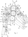
- fig. 1 shows diagrammatically a perspective view of an embodiment of the device according to the invention;
- fig. 2 is a view according to fig. 1 in which a medium format of printing cylinders is supported;
- fig. 3 is a view according to fig. 1 in which a large format of printing cylinders is supported;
- fig. 4 is a view according to fig. 3 in which the bearing arms on the left side are lowered to a replacement position;
- fig. 5 shows a side view of a variant embodiment of the device in figs. 1-4;
- fig. 6 is a view according to fig. 5 in which a large format of printing cylinders is supported;
- fig. 7 shows diagrammatically an embodiment having three sets of co-operating bearing arms;
- fig. 8 shows an embodiment in which the positioning elements are two cones that are to be moved axially; and
- fig. 9 shows the positioning element in the form of a through running mandrel with a clamping device.
-
- In fig. 1 the device comprises a printing assembly having three printing cylinders, namely an
image printing cylinder 1, atransfer printing cylinder 2 and animpression printing cylinder 3. Theimage printing cylinder 1 is supported in a fixed position with respect to a U-shaped supporting construction 4. Thetransfer printing cylinder 2 is supported on both ends between supporting elements 5. Theimpression printing cylinder 3 is supported on both ends between supportingelements 6. Each supporting element 5 is provided on afirst bearing arm 8. Each supportingelement 6 is provided on asecond bearing arm 9. Eachbearing arm axis 10. Thefirst bearing arm 8 is connected to first actuating means 12 for rotating thebearing arm 8 and supporting element 5 through predetermined angles around theaxis 10. Thesecond bearing arm 9 is connected to second actuating means 13 for rotating thebearing arm 9 and supportingelement 6 through predetermined angles with respect to theaxis 10. In the embodiment shown the second actuating means 13 are connected to thefirst bearing arm 8, causing the second actuating means 13 to move along with a rotation of thefirst bearing arm 8 if the first actuating means 12 are actuated. - Both the first and second actuating means 12, 13 comprise an adjustable distance device, which in the embodiment shown is formed by a screw spindle. The component parts of the screw spindle of the first actuating means 12 are pivotably connected to the
bearing arm 8 and to a fixedpoint 15 on the supporting construction 4. Adrive 16 is provided for accurately rotating the screw spindle, resulting in an upward or downward movement of anut element 17 connected pivotably to thefirst bearing arm 8. Component parts of the second actuating means 13 comprise adrive 18 pivotably connected to thefirst bearing arm 8 for driving the screw spindle, resulting in an upward or downward movement of anut element 19 pivotably connected to thesecond bearing arm 9. The side walls of the supporting construction 4 are each provided withopenings openings arms elements 5, 6 mounted thereon, together with theprinting cylinders image printing cylinder 1. - The main advantage of the construction described above can be seen in fig. 2 and 3, in which the bearing
arms image printing cylinder 1" andtransfer printing cylinder 2" (fig. 3) respectively. - Furthermore a suitable actuation of the actuating means 12, 13 makes it possible to accurately position the printing cylinders 1-3 with respect to each other such that the pressure on the contact area between the
image printing cylinder 1 andtransfer printing cylinder 2 is approximately equal to the pressure on the contact area between thetransfer printing cylinder 2 and theimpression printing cylinder 3. This makes it possible to achieve a very good printing quality for sheets to be printed which are guided between thetransfer printing cylinder 2 and theimpression cylinder 3, even when substrate having different thickness is being used. - During use the
image printing cylinder 1 is provided with ink from an inking mechanism (not shown) positioned above theimage printing cylinder 1. The inking mechanism is movably supported with respect to theimage printing cylinder 1 in order to be able to ink different formats of image printing cylinders. - In fig. 4 the first and
second bearing arms second bearing arm 9 on the right side of the device are rotated to a lower replacing position, while the left supporting element 5 on thefirst bearing arm 8 is disconnected from thetransfer printing cylinder 2". Theimpression printing cylinder 3 is moved along downwards together with its supportingelements 6 on the bearingarms 9. Thebearing arm 8 on the right side is maintained in its upper supporting position and solely supports thetransfer printing cylinder 2". Theopening 20 in the left side wall of the supporting construction 4 is made large enough for theimage printing cylinder 1" and thetransfer printing cylinder 2" to be taken out of the device sideways. Thus it is easily possible to replace the format dependent printing cylinders for cylinders with the same or another format, by means of a separate actuating of the rotation of the bearing arms. - Figs. 5 and 6 show embodiments greatly similar to the embodiments shown in figs. 1-4, with the difference that first and second bearing
arms own axis first bearing arm 51 are indirectly connected to second actuating means 56 for thesecond bearing arm 52. In a variant not shown the actuating means may not be interconnected. Fig. 6 shows the device supporting a larger format ofprinting cylinders axes axes - In fig. 7 three
printing cylinders arms printing cylinders - The bearing
arms rotation arms ball circulation spindles elements Spindle 82 is fitted on a fixed centre ofrotation 87 and is further connected to apivot point 90 provided on bearingarm 75,spindle 80 is connected by way ofpivot point 86 and fixing plate 86' to bearingarm 75, and by way ofpivot point 89 and fixingarm 92 to bearingarm 74, andspindle 81 is connected by way ofpivot point 88 and fixingarm 93 to bearingarm 75 and by way ofpivot point 91 and fixingarm 94 to bearingarm 76. - For the movement of the
elements motors pulse generators - The fig. further shows the
drive motors respective cylinders motors arms - Since in principle it is not format-dependent and therefore does not have to be changed, the
impression cylinder 73 is fitted immovably between the bearing arms. For bringing the impression cylinder up to pressure and releasing it from pressure, use is made of the positioning means of the bearing arms, so that the usual eccentrics for the impression cylinders can be dispensed with here. - Furthermore, in the case of an impression cylinder the possibility for enabling axial movement of the cylinder is not necessary, so that there again no drive facility need be provided for it on the bearing arm. The possibility of axial displacement of the printing cylinders is intended for permitting positioning of the printed image correctly on the web, so that in principle an axial movement possibility for the plate cylinder alone would suffice.
- Fig. 8 shows a section through the bearing
arms 74, 74' withdrive motor 101 and supportingelements cones - The supporting
elements screw spindles element toothed belts toothed belt motors 104 is shown in fig. 1. Instead of atoothed belt spindles - The
drive motor 101 is connected by way of adirect transmission 118 to ashaft part 119 of the supportingelement 106. - Finally, fig. 9 shows a section of a possible supporting element which is substantially composed of a through-running
mandrel 137, over which aprinting cylinder 131 is pushed and clamped there with the aid of aclamping device 138. Theclamping device 138 is supported in apart 139 of a housing which is fitted in a printing tower, and which can be removed or folded away together with theclamping device 138, with the result that sufficient space is produced to permit removal of a cylinder from themandrel 137 or sliding of a cylinder onto the mandrel in the axial direction. - On the drive side, drive
motor 101 is connected by way of aspline shaft 141 to theshaft 142 of themandrel 137, provision further being made for a drive mechanism 140 for permitting adjustment of themandrel 137 in the axial direction. Instead of a spline shaft, it is also possible, for example, to provide an axially adjustable coupling or a combination of two fixed gear wheels. - Besides the embodiments shown numerous variants are possible. For example a printing assembly having four printing cylinders may be provided for double sided printing of sheets, that is to say two image printing cylinders and two transfer printing cylinders. With this supporting elements for at least three of the cylinders are provided on first, second and third bearing arms each rotatable about an axis, the positioning means comprising first, second and third actuating means for rotating each respective bearing arm and supporting element through predetermined angles. Furthermore, the actuating means may also be formed by a worm-gear mechanism connected to the bearing arm. Instead of bearing arms on both sides of the printing cylinders, it is also possible to provide bearing arms on only one side of the printing cylinders.
- Thus the device according to the invention makes it possible to provide for a quick and easy adjustment of an offset printing press for printing different formats of substrate, and/or for printing different substrate thickness. The at least two sets of bearing arms make it possible to accurately position the printing cylinders with respect to each other, resulting in a superb printing quality.
Claims (13)
- Device for use in an offset printing press for supporting and positioning of printing cylinders of the printing press exchangeably therein,characterized in thatthe printing press or one or more component modules thereof being provided with a printing assembly having at least three printing cylinders (1, 2, 3), and a drive being provided for the cylinders,the device being provided with supporting elements (5, 6) for exchangeably supporting at least two of the cylinders (2, 3), and positioning means for positioning at least one of the cylinders,in which the supporting element (5, 6) for at least one cylinder (2, 3) is provided on a bearing arm (8, 9) that is rotatable about an axis (10), the positioning means comprising actuating means (12, 13) for rotating of the bearing arm (8, 9) and supporting element (5, 6) through a predetermined angle, with the result that at least one cylinder (1, 2) can be exchanged for a cylinder (1', 2', 1", 2") of the same or another format,
the supporting elements (5, 6) for at least two of the cylinders (2, 3) are provided on first and second bearing arms (8, 9) each rotatable about an axis (10), the positioning means comprising first and second actuating means (12, 13) for rotating of each respective bearing arm (8, 9) and supporting element (5, 6) through predetermined angles. - Device according to claim 1, in which the first actuating means (12) are rotatably connected to a fixed point (15) and the first bearing arm (8), and the second actuating means (13) are rotatably connected to the first bearing arm (8) and the second bearing arm (9).
- Device according to claim 1 or 2, in which the actuating means (12, 13) for at least one bearing arm (8, 9) comprises an adjustable distance device whose component parts are pivotably connected to this bearing arm (8, 9) and to a fixed point (15) or other bearing arm (8) respectively.
- Device according to claim 3, in which the adjustable distance device is a screw spindle.
- Device according to claim 4, in which a detection device is provided for detection of the angle of rotation of a drive shaft or driven element on the screw spindle.
- Device according to one of the preceding claims, in which three supporting elements are provided for supporting three printing cylinders (1, 2, 3), one supporting element of which is in a fixed position.
- Device according to claim 6, in which the three printing cylinders (1, 2, 3) are an image printing cylinder (1), a transfer printing cylinder (2) and an impression printing cylinder (3), of which the image printing cylinder (1) is in a fixed position.
- Device according to one of the preceding claims, in which at least one supporting element (106, 107) is axially movable, the movement of this supporting element (106, 107) being possible by means of a drive (110-113) fitted on a bearing arm (74) or supporting member.
- Device according to one of the preceding claims, in which a supporting element is substantially composed of a mandrel (137) provided with a clamping device (138) for clamping a printing cylinder (131) on the mandrel (137).
- Device according to one of the preceding claims, in which for synchronous running of the printing cylinders provision is made for a fixed action point between a supporting element and a printing cylinder.
- Device according to one of the preceding claims, in which the supporting elements (60, 61, 62) are positionable with respect to each other such that the axes thereof are approximately in line.
- Device according to one of the preceding claims, in which for each of the at least two cylinders (2, 3) to be supported by bearing arms (8, 9), a set of opposite bearing arms (8, 9) is provided, each bearing arm (8, 9) being provided with a supporting element (5, 6).
- Device according to claim 12, in which the bearing arms (8, 9) of the same set are separately rotatable.
Applications Claiming Priority (2)
| Application Number | Priority Date | Filing Date | Title |
|---|---|---|---|
| NL1013620A NL1013620C2 (en) | 1999-11-19 | 1999-11-19 | Device for interchangeably receiving and positioning the printing cylinders of an offset printing press. |
| NL1013620 | 1999-11-19 |
Publications (2)
| Publication Number | Publication Date |
|---|---|
| EP1101611A1 true EP1101611A1 (en) | 2001-05-23 |
| EP1101611B1 EP1101611B1 (en) | 2004-02-11 |
Family
ID=19770288
Family Applications (1)
| Application Number | Title | Priority Date | Filing Date |
|---|---|---|---|
| EP00204070A Expired - Lifetime EP1101611B1 (en) | 1999-11-19 | 2000-11-17 | Device for exchangeably supporting and positioning printing cylinders of an offset printing press |
Country Status (6)
| Country | Link |
|---|---|
| US (1) | US6694877B1 (en) |
| EP (1) | EP1101611B1 (en) |
| AT (1) | ATE259300T1 (en) |
| DE (1) | DE60008196T2 (en) |
| ES (1) | ES2215567T3 (en) |
| NL (1) | NL1013620C2 (en) |
Cited By (20)
| Publication number | Priority date | Publication date | Assignee | Title |
|---|---|---|---|---|
| WO2004012941A3 (en) * | 2002-07-31 | 2004-05-06 | Komori Chambon | Printing machine |
| WO2004056569A2 (en) * | 2002-12-21 | 2004-07-08 | Man Roland Druckmaschinen Ag | Modular printing unit |
| WO2004065123A1 (en) | 2002-12-18 | 2004-08-05 | Drent Holding B.V. | Web-fed rotary press |
| NL1022758C2 (en) * | 2003-02-21 | 2004-08-24 | Drent Graphic Machines | Printing cylinder support unit is for use in offset printing press and comprises frame and three carrying devices |
| EP1449656A1 (en) | 2003-02-19 | 2004-08-25 | Müller Martini Holding AG | Printing unit for indirect printing |
| EP1559548A1 (en) * | 2004-01-28 | 2005-08-03 | RDP Marathon Inc. | Rolling element adjustment system |
| EP1568494A1 (en) | 2004-02-27 | 2005-08-31 | Müller Martini Holding AG | Device for realising variable format offset printing |
| EP1661701A1 (en) * | 2004-11-26 | 2006-05-31 | MAN Roland Druckmaschinen AG | Inking unit of a printing machine |
| EP1754601A1 (en) | 2005-08-15 | 2007-02-21 | Müller Martini Holding AG | Printing unit for a printing machine, with bearer rings on exchangeable cylinders |
| US7293503B2 (en) | 2004-02-27 | 2007-11-13 | Müller Martini Holding AG | Slide-in print unit for a variable format in offset printing |
| DE102007017097A1 (en) * | 2006-09-15 | 2008-03-27 | Sdf Schnitt-Druck-Falz Spezialmaschinen Gmbh | Print cylinder changer system for variable print length printing mechanisms in a full rotation printing machine has printing cylinder with rotary driven core and print cylinder sleeve that is replaceable to adapt to print length |
| EP2042315A2 (en) | 2007-09-25 | 2009-04-01 | Gallus Druckmaschinen GmbH | Printing unit and printing press |
| DE102008013315A1 (en) | 2008-03-10 | 2009-09-17 | Gallus Druckmaschinen Gmbh | Printing unit and printing press |
| WO2010034855A1 (en) | 2008-09-29 | 2010-04-01 | Neopack, S.L. | Printing machine and printing group for variable format offset |
| EP2407307A1 (en) * | 2010-07-15 | 2012-01-18 | Goss International Americas, Inc. | Variable cutoff printing unit and method |
| EP2450191A1 (en) | 2010-11-05 | 2012-05-09 | Neopack, S.L. | Variable format offset printing machine having a central impression cylinder |
| DE202010017754U1 (en) | 2010-11-05 | 2012-07-09 | Neopack, S.L. | Offset printing machine for variable formals with central impression cylinder |
| DE102011055817A1 (en) | 2011-11-29 | 2013-05-29 | Sdf Schnitt-Druck-Falz Spezialmaschinen Gmbh | Printing unit for offset printing, has two fixed side frames for pivot bearing, plate cylinder which consists of cylinder core and cylinder sleeve, and rubber blanket cylinder applied against plate cylinder |
| EP2945803B1 (en) | 2013-01-15 | 2017-07-26 | Omet S.r.L. | Printing unit for variable-format offset printing presses |
| DE202023105103U1 (en) | 2023-09-05 | 2023-09-19 | Manroland Goss Web Systems Gmbh | Printing unit with movable printing cylinders |
Families Citing this family (14)
| Publication number | Priority date | Publication date | Assignee | Title |
|---|---|---|---|---|
| NL1022048C2 (en) * | 2002-12-02 | 2004-06-03 | Mps Holding B V | Printing module as well as a printing machine provided with such a printing module. |
| NL1026736C2 (en) * | 2004-07-28 | 2006-01-31 | Stork Prints Bv | Printing cylinder support unit, positioning element, printing cylinder provided with positioning element, printing machine provided with printing cylinder support unit, and use thereof. |
| US8435284B2 (en) * | 2005-12-14 | 2013-05-07 | Boston Scientific Scimed, Inc. | Telescoping bifurcated stent |
| CN101041285B (en) * | 2006-03-24 | 2010-04-14 | 海德堡印刷机械股份公司 | Printing press |
| US20080141879A1 (en) * | 2006-12-18 | 2008-06-19 | Goss International Corporation | Gear driven variable cutoff printing press |
| US20110132216A1 (en) * | 2009-12-09 | 2011-06-09 | 7242514 Canada Inc. | Stack angle compensation arrangement for a skewing adjustment system in an offset printing press |
| DE102011100686A1 (en) * | 2010-05-21 | 2012-11-08 | Goebel Gmbh | Processing machine with at least one printing unit |
| DE102011100758A1 (en) | 2010-05-21 | 2012-09-27 | Goebel Gmbh | Processing machine with at least one printing unit |
| US8919250B2 (en) | 2010-08-02 | 2014-12-30 | Goss International Americas, Inc. | Printing press and method for positioning cylinders therein |
| US20140102324A1 (en) | 2012-10-17 | 2014-04-17 | Goss International Americas, Inc. | Variable cutoff printing press with actuators for moving blanket and impression cylinder supports |
| US8985017B2 (en) * | 2012-10-17 | 2015-03-24 | Goss International Americas, Inc. | Variable cutoff printing press with off impression gap |
| CN106696441B (en) * | 2016-12-05 | 2018-09-18 | 高斯图文印刷系统(中国)有限公司 | A kind of drive transmission device of variable format printing machine |
| CN107639923A (en) * | 2017-09-14 | 2018-01-30 | 浙江炜冈机械有限公司 | The printing mechanism of offset press |
| CN107584861B (en) * | 2017-09-29 | 2023-03-17 | 浙江炜冈科技股份有限公司 | Printing unit comprising offset printing unit and flexo printing unit |
Citations (5)
| Publication number | Priority date | Publication date | Assignee | Title |
|---|---|---|---|---|
| US2753797A (en) * | 1952-03-27 | 1956-07-10 | Burgmer Josef | Rotary printing and cutting machine with interchangeable printing cylinders |
| FR1572556A (en) * | 1967-05-26 | 1969-06-27 | ||
| US3611924A (en) * | 1969-10-23 | 1971-10-12 | Nat Productive Machines Inc | Rotary offset printing press with cylinder interrupter |
| US4413541A (en) * | 1980-03-10 | 1983-11-08 | Elizabeth Short Biggar | Rapid changeover printer |
| GB2334234A (en) * | 1998-02-13 | 1999-08-18 | Roland Man Druckmasch | Printing unit for a web press |
Family Cites Families (6)
| Publication number | Priority date | Publication date | Assignee | Title |
|---|---|---|---|---|
| US3150588A (en) * | 1961-05-25 | 1964-09-29 | Block & Anderson Ltd | Cylinder mounting, adjusting and interrupting means for offset printing and like machines |
| US5351616A (en) | 1992-08-13 | 1994-10-04 | Man Roland Druckmaschinen Ag | Rotary web printing machine, particularly for printing on thick or carton-type stock webs with replaceable plate cylinders |
| DE19614397C2 (en) * | 1996-04-12 | 2001-04-26 | Roland Man Druckmasch | Drive with register device for a printing unit of a web-fed rotary printing press |
| US5943955A (en) * | 1997-08-29 | 1999-08-31 | Goss Graphic Systems, Inc. | Printing press having cantilevered self-driven cylinders |
| US6227111B1 (en) * | 1998-10-21 | 2001-05-08 | Heidelberger Druckmaschinen Ag | Impression setting mechanism for a printing unit |
| US6272985B1 (en) * | 1999-09-07 | 2001-08-14 | Kelray Tech, Inc. | Link arm mechanism for adjustable spacing of plate and blanket cylinders in a rotary offset printing press |
-
1999
- 1999-11-19 NL NL1013620A patent/NL1013620C2/en not_active IP Right Cessation
-
2000
- 2000-11-17 EP EP00204070A patent/EP1101611B1/en not_active Expired - Lifetime
- 2000-11-17 DE DE60008196T patent/DE60008196T2/en not_active Expired - Lifetime
- 2000-11-17 ES ES00204070T patent/ES2215567T3/en not_active Expired - Lifetime
- 2000-11-17 US US09/715,305 patent/US6694877B1/en not_active Expired - Lifetime
- 2000-11-17 AT AT00204070T patent/ATE259300T1/en not_active IP Right Cessation
Patent Citations (5)
| Publication number | Priority date | Publication date | Assignee | Title |
|---|---|---|---|---|
| US2753797A (en) * | 1952-03-27 | 1956-07-10 | Burgmer Josef | Rotary printing and cutting machine with interchangeable printing cylinders |
| FR1572556A (en) * | 1967-05-26 | 1969-06-27 | ||
| US3611924A (en) * | 1969-10-23 | 1971-10-12 | Nat Productive Machines Inc | Rotary offset printing press with cylinder interrupter |
| US4413541A (en) * | 1980-03-10 | 1983-11-08 | Elizabeth Short Biggar | Rapid changeover printer |
| GB2334234A (en) * | 1998-02-13 | 1999-08-18 | Roland Man Druckmasch | Printing unit for a web press |
Cited By (37)
| Publication number | Priority date | Publication date | Assignee | Title |
|---|---|---|---|---|
| WO2004012941A3 (en) * | 2002-07-31 | 2004-05-06 | Komori Chambon | Printing machine |
| US7377216B2 (en) | 2002-07-31 | 2008-05-27 | Komori-Chambon S.A. | Printing machine having fixed paper cylinder |
| WO2004065123A1 (en) | 2002-12-18 | 2004-08-05 | Drent Holding B.V. | Web-fed rotary press |
| WO2004056569A2 (en) * | 2002-12-21 | 2004-07-08 | Man Roland Druckmaschinen Ag | Modular printing unit |
| WO2004056569A3 (en) * | 2002-12-21 | 2004-08-05 | Roland Man Druckmasch | Modular printing unit |
| US7350464B2 (en) | 2002-12-21 | 2008-04-01 | Man Roland Druckmaschinen Ag | Modular printing unit |
| EP1449656A1 (en) | 2003-02-19 | 2004-08-25 | Müller Martini Holding AG | Printing unit for indirect printing |
| NL1022758C2 (en) * | 2003-02-21 | 2004-08-24 | Drent Graphic Machines | Printing cylinder support unit is for use in offset printing press and comprises frame and three carrying devices |
| WO2004103707A1 (en) * | 2003-02-21 | 2004-12-02 | Drent Holding B.V. | Printing cylinder support unit for use in an offset printing press |
| US7270057B2 (en) | 2004-01-28 | 2007-09-18 | Rdp Marathon Inc. | Rolling element adjustment system |
| EP1559548A1 (en) * | 2004-01-28 | 2005-08-03 | RDP Marathon Inc. | Rolling element adjustment system |
| EP1568494A1 (en) | 2004-02-27 | 2005-08-31 | Müller Martini Holding AG | Device for realising variable format offset printing |
| US7293503B2 (en) | 2004-02-27 | 2007-11-13 | Müller Martini Holding AG | Slide-in print unit for a variable format in offset printing |
| US7389726B2 (en) | 2004-02-27 | 2008-06-24 | Muller Martini Holding Ag | Device for producing print images of varying lengths in offset printing |
| EP1661701A1 (en) * | 2004-11-26 | 2006-05-31 | MAN Roland Druckmaschinen AG | Inking unit of a printing machine |
| EP1754601A1 (en) | 2005-08-15 | 2007-02-21 | Müller Martini Holding AG | Printing unit for a printing machine, with bearer rings on exchangeable cylinders |
| DE102007017097A1 (en) * | 2006-09-15 | 2008-03-27 | Sdf Schnitt-Druck-Falz Spezialmaschinen Gmbh | Print cylinder changer system for variable print length printing mechanisms in a full rotation printing machine has printing cylinder with rotary driven core and print cylinder sleeve that is replaceable to adapt to print length |
| DE102007017097B4 (en) * | 2006-09-15 | 2011-06-01 | Sdf Schnitt-Druck-Falz Spezialmaschinen Gmbh | Printing cylinder changing device for printing length variable printing units in a full rotation printing press |
| DE102007045876A1 (en) | 2007-09-25 | 2009-04-09 | Gallus Druckmaschinen Gmbh | Printing unit and printing press |
| EP2042315A2 (en) | 2007-09-25 | 2009-04-01 | Gallus Druckmaschinen GmbH | Printing unit and printing press |
| CN101396900B (en) * | 2007-09-25 | 2012-02-22 | 捷拉斯印刷机械有限公司 | Printing unit and printing press |
| US8499691B2 (en) | 2008-03-10 | 2013-08-06 | Gallus Druckmaschinen Gmbh | Printing unit, printing press and process for producing labels in a printing press |
| EP2103429A1 (en) | 2008-03-10 | 2009-09-23 | Gallus Druckmaschinen GmbH | Printing unit and press with format change |
| DE102008013315A1 (en) | 2008-03-10 | 2009-09-17 | Gallus Druckmaschinen Gmbh | Printing unit and printing press |
| WO2010034855A1 (en) | 2008-09-29 | 2010-04-01 | Neopack, S.L. | Printing machine and printing group for variable format offset |
| US8746141B2 (en) | 2008-09-29 | 2014-06-10 | Neopak, Sl | Printing machine and printing group for variable format offset |
| DE112009002489T5 (en) | 2008-09-29 | 2012-09-13 | Neopack, S.L. | Printing press and printing group for format variable offset |
| EP2407307A1 (en) * | 2010-07-15 | 2012-01-18 | Goss International Americas, Inc. | Variable cutoff printing unit and method |
| CN102407654A (en) * | 2010-07-15 | 2012-04-11 | 高斯国际美洲公司 | Printing mechanism of variable cutoff printing unit |
| US8850975B2 (en) | 2010-07-15 | 2014-10-07 | Goss International Americas, Inc. | Impression mechanism for a variable cutoff printing unit |
| WO2012059801A1 (en) | 2010-11-05 | 2012-05-10 | Neopack Sl | Variable format offset printing machine having a central impression cylinder |
| EP2559553A2 (en) | 2010-11-05 | 2013-02-20 | Neopack, S.L. | Variable format offset printing machine having a central impression cylinder |
| DE202010017754U1 (en) | 2010-11-05 | 2012-07-09 | Neopack, S.L. | Offset printing machine for variable formals with central impression cylinder |
| EP2450191A1 (en) | 2010-11-05 | 2012-05-09 | Neopack, S.L. | Variable format offset printing machine having a central impression cylinder |
| DE102011055817A1 (en) | 2011-11-29 | 2013-05-29 | Sdf Schnitt-Druck-Falz Spezialmaschinen Gmbh | Printing unit for offset printing, has two fixed side frames for pivot bearing, plate cylinder which consists of cylinder core and cylinder sleeve, and rubber blanket cylinder applied against plate cylinder |
| EP2945803B1 (en) | 2013-01-15 | 2017-07-26 | Omet S.r.L. | Printing unit for variable-format offset printing presses |
| DE202023105103U1 (en) | 2023-09-05 | 2023-09-19 | Manroland Goss Web Systems Gmbh | Printing unit with movable printing cylinders |
Also Published As
| Publication number | Publication date |
|---|---|
| EP1101611B1 (en) | 2004-02-11 |
| ATE259300T1 (en) | 2004-02-15 |
| NL1013620C2 (en) | 2001-05-22 |
| ES2215567T3 (en) | 2004-10-16 |
| DE60008196D1 (en) | 2004-03-18 |
| DE60008196T2 (en) | 2004-12-16 |
| US6694877B1 (en) | 2004-02-24 |
Similar Documents
| Publication | Publication Date | Title |
|---|---|---|
| EP1101611B1 (en) | Device for exchangeably supporting and positioning printing cylinders of an offset printing press | |
| AU2010334375B9 (en) | Intaglio printing press with mobile carriage supporting ink-collecting cylinder | |
| JP3325651B2 (en) | Multipurpose printing press system with printing cylinders of different cutoff dimensions | |
| US4729309A (en) | Imprinter | |
| US5301609A (en) | Printing unit with skew and throw-off mechanisms | |
| JPH0469546B2 (en) | ||
| JPH0373465B2 (en) | ||
| US6293194B1 (en) | Method and apparatus for adjusting the circumferential register in a web-fed rotary printing press having a plate cylinder with a sleeve-shaped printing plate | |
| US20030019374A1 (en) | Flexographic printing machine | |
| JP4406097B2 (en) | Printer | |
| WO1996005966A1 (en) | Engraver cylinder support method and apparatus | |
| US6829992B2 (en) | Paper web width adjustment device | |
| CA2435174C (en) | Apparatus for setting the lateral register for printing units of rotary presses | |
| KR100865916B1 (en) | Printing module, and printing machine provided with such printing module | |
| AU711032B2 (en) | Printing plate mounting structure | |
| US7231796B1 (en) | Structure of roll-forming machine | |
| AU721024B2 (en) | Lithographic imaging system for interchangeable plate cylinders | |
| WO1987004665A1 (en) | Printing apparatus | |
| US6945169B2 (en) | Apparatus for producing printing plates | |
| CN101631679B (en) | Cantilevered blanket cylinder lifting mechanism | |
| CN102059846A (en) | Horizontal printing single unit for rotary printing press | |
| JP2921656B2 (en) | Sheet transfer cylinder for rotary printing presses | |
| JP3746818B2 (en) | Plate cylinder support device | |
| CN115027126B (en) | Bottom die quick-change assembly and rotary printing machine | |
| US5778780A (en) | Printing press with nip adjustment |
Legal Events
| Date | Code | Title | Description |
|---|---|---|---|
| PUAI | Public reference made under article 153(3) epc to a published international application that has entered the european phase |
Free format text: ORIGINAL CODE: 0009012 |
|
| AK | Designated contracting states |
Kind code of ref document: A1 Designated state(s): AT BE CH CY DE DK ES FI FR GB GR IE IT LI LU MC NL PT SE TR |
|
| AX | Request for extension of the european patent |
Free format text: AL;LT;LV;MK;RO;SI |
|
| 17P | Request for examination filed |
Effective date: 20010817 |
|
| AKX | Designation fees paid |
Free format text: AT BE CH CY DE DK ES FI FR GB GR IE IT LI LU MC NL PT SE TR |
|
| GRAH | Despatch of communication of intention to grant a patent |
Free format text: ORIGINAL CODE: EPIDOS IGRA |
|
| GRAP | Despatch of communication of intention to grant a patent |
Free format text: ORIGINAL CODE: EPIDOSNIGR1 |
|
| GRAS | Grant fee paid |
Free format text: ORIGINAL CODE: EPIDOSNIGR3 |
|
| GRAA | (expected) grant |
Free format text: ORIGINAL CODE: 0009210 |
|
| AK | Designated contracting states |
Kind code of ref document: B1 Designated state(s): AT BE CH CY DE DK ES FI FR GB GR IE IT LI LU MC NL PT SE TR |
|
| PG25 | Lapsed in a contracting state [announced via postgrant information from national office to epo] |
Ref country code: AT Free format text: LAPSE BECAUSE OF FAILURE TO SUBMIT A TRANSLATION OF THE DESCRIPTION OR TO PAY THE FEE WITHIN THE PRESCRIBED TIME-LIMIT Effective date: 20040211 Ref country code: FI Free format text: LAPSE BECAUSE OF FAILURE TO SUBMIT A TRANSLATION OF THE DESCRIPTION OR TO PAY THE FEE WITHIN THE PRESCRIBED TIME-LIMIT Effective date: 20040211 Ref country code: TR Free format text: LAPSE BECAUSE OF FAILURE TO SUBMIT A TRANSLATION OF THE DESCRIPTION OR TO PAY THE FEE WITHIN THE PRESCRIBED TIME-LIMIT Effective date: 20040211 Ref country code: CY Free format text: LAPSE BECAUSE OF FAILURE TO SUBMIT A TRANSLATION OF THE DESCRIPTION OR TO PAY THE FEE WITHIN THE PRESCRIBED TIME-LIMIT Effective date: 20040211 |
|
| REG | Reference to a national code |
Ref country code: GB Ref legal event code: FG4D |
|
| REG | Reference to a national code |
Ref country code: CH Ref legal event code: EP |
|
| REG | Reference to a national code |
Ref country code: IE Ref legal event code: FG4D |
|
| REF | Corresponds to: |
Ref document number: 60008196 Country of ref document: DE Date of ref document: 20040318 Kind code of ref document: P |
|
| REG | Reference to a national code |
Ref country code: CH Ref legal event code: NV Representative=s name: NOVAGRAAF INTERNATIONAL SA |
|
| PG25 | Lapsed in a contracting state [announced via postgrant information from national office to epo] |
Ref country code: DK Free format text: LAPSE BECAUSE OF FAILURE TO SUBMIT A TRANSLATION OF THE DESCRIPTION OR TO PAY THE FEE WITHIN THE PRESCRIBED TIME-LIMIT Effective date: 20040511 Ref country code: GR Free format text: LAPSE BECAUSE OF FAILURE TO SUBMIT A TRANSLATION OF THE DESCRIPTION OR TO PAY THE FEE WITHIN THE PRESCRIBED TIME-LIMIT Effective date: 20040511 Ref country code: SE Free format text: LAPSE BECAUSE OF FAILURE TO SUBMIT A TRANSLATION OF THE DESCRIPTION OR TO PAY THE FEE WITHIN THE PRESCRIBED TIME-LIMIT Effective date: 20040511 |
|
| REG | Reference to a national code |
Ref country code: ES Ref legal event code: FG2A Ref document number: 2215567 Country of ref document: ES Kind code of ref document: T3 |
|
| ET | Fr: translation filed | ||
| PG25 | Lapsed in a contracting state [announced via postgrant information from national office to epo] |
Ref country code: LU Free format text: LAPSE BECAUSE OF NON-PAYMENT OF DUE FEES Effective date: 20041117 Ref country code: IE Free format text: LAPSE BECAUSE OF NON-PAYMENT OF DUE FEES Effective date: 20041117 |
|
| PG25 | Lapsed in a contracting state [announced via postgrant information from national office to epo] |
Ref country code: MC Free format text: LAPSE BECAUSE OF NON-PAYMENT OF DUE FEES Effective date: 20041130 |
|
| PLBE | No opposition filed within time limit |
Free format text: ORIGINAL CODE: 0009261 |
|
| STAA | Information on the status of an ep patent application or granted ep patent |
Free format text: STATUS: NO OPPOSITION FILED WITHIN TIME LIMIT |
|
| 26N | No opposition filed |
Effective date: 20041112 |
|
| REG | Reference to a national code |
Ref country code: IE Ref legal event code: MM4A |
|
| PG25 | Lapsed in a contracting state [announced via postgrant information from national office to epo] |
Ref country code: PT Free format text: LAPSE BECAUSE OF NON-PAYMENT OF DUE FEES Effective date: 20040711 |
|
| NLS | Nl: assignments of ep-patents |
Owner name: MUELLER MARTINI DRUCKMASCHINEN GMBH Effective date: 20091026 |
|
| REG | Reference to a national code |
Ref country code: CH Ref legal event code: PUE Owner name: MUELLER MARTINI DRUCKMASCHINEN GMBH Free format text: DRENT HOLDING B.V.#HALLSEWEG 21#6964 AJ HALL (NL) -TRANSFER TO- MUELLER MARTINI DRUCKMASCHINEN GMBH#FELDBERGSTRASSE 20#78690 MAULBURG (DE) |
|
| REG | Reference to a national code |
Ref country code: GB Ref legal event code: 732E Free format text: REGISTERED BETWEEN 20100429 AND 20100505 |
|
| REG | Reference to a national code |
Ref country code: FR Ref legal event code: TP |
|
| REG | Reference to a national code |
Ref country code: ES Ref legal event code: PC2A |
|
| REG | Reference to a national code |
Ref country code: FR Ref legal event code: PLFP Year of fee payment: 16 |
|
| REG | Reference to a national code |
Ref country code: FR Ref legal event code: PLFP Year of fee payment: 17 |
|
| REG | Reference to a national code |
Ref country code: FR Ref legal event code: PLFP Year of fee payment: 18 |
|
| PGFP | Annual fee paid to national office [announced via postgrant information from national office to epo] |
Ref country code: NL Payment date: 20181123 Year of fee payment: 19 |
|
| PGFP | Annual fee paid to national office [announced via postgrant information from national office to epo] |
Ref country code: DE Payment date: 20181116 Year of fee payment: 19 |
|
| PGFP | Annual fee paid to national office [announced via postgrant information from national office to epo] |
Ref country code: GB Payment date: 20181123 Year of fee payment: 19 Ref country code: ES Payment date: 20181214 Year of fee payment: 19 Ref country code: FR Payment date: 20181123 Year of fee payment: 19 Ref country code: IT Payment date: 20181130 Year of fee payment: 19 Ref country code: BE Payment date: 20181119 Year of fee payment: 19 |
|
| PGFP | Annual fee paid to national office [announced via postgrant information from national office to epo] |
Ref country code: CH Payment date: 20190222 Year of fee payment: 19 |
|
| REG | Reference to a national code |
Ref country code: DE Ref legal event code: R119 Ref document number: 60008196 Country of ref document: DE |
|
| REG | Reference to a national code |
Ref country code: CH Ref legal event code: PL |
|
| REG | Reference to a national code |
Ref country code: NL Ref legal event code: MM Effective date: 20191201 |
|
| PG25 | Lapsed in a contracting state [announced via postgrant information from national office to epo] |
Ref country code: CH Free format text: LAPSE BECAUSE OF NON-PAYMENT OF DUE FEES Effective date: 20191130 Ref country code: LI Free format text: LAPSE BECAUSE OF NON-PAYMENT OF DUE FEES Effective date: 20191130 |
|
| REG | Reference to a national code |
Ref country code: BE Ref legal event code: MM Effective date: 20191130 |
|
| GBPC | Gb: european patent ceased through non-payment of renewal fee |
Effective date: 20191117 |
|
| PG25 | Lapsed in a contracting state [announced via postgrant information from national office to epo] |
Ref country code: NL Free format text: LAPSE BECAUSE OF NON-PAYMENT OF DUE FEES Effective date: 20191201 |
|
| PG25 | Lapsed in a contracting state [announced via postgrant information from national office to epo] |
Ref country code: IT Free format text: LAPSE BECAUSE OF NON-PAYMENT OF DUE FEES Effective date: 20191117 Ref country code: DE Free format text: LAPSE BECAUSE OF NON-PAYMENT OF DUE FEES Effective date: 20200603 Ref country code: GB Free format text: LAPSE BECAUSE OF NON-PAYMENT OF DUE FEES Effective date: 20191117 Ref country code: FR Free format text: LAPSE BECAUSE OF NON-PAYMENT OF DUE FEES Effective date: 20191130 |
|
| PG25 | Lapsed in a contracting state [announced via postgrant information from national office to epo] |
Ref country code: BE Free format text: LAPSE BECAUSE OF NON-PAYMENT OF DUE FEES Effective date: 20191130 |
|
| REG | Reference to a national code |
Ref country code: ES Ref legal event code: FD2A Effective date: 20210526 |
|
| PG25 | Lapsed in a contracting state [announced via postgrant information from national office to epo] |
Ref country code: ES Free format text: LAPSE BECAUSE OF NON-PAYMENT OF DUE FEES Effective date: 20191118 |