EP1100424B1 - Tampon mit flexiblen flügeln - Google Patents
Tampon mit flexiblen flügeln Download PDFInfo
- Publication number
- EP1100424B1 EP1100424B1 EP99938856A EP99938856A EP1100424B1 EP 1100424 B1 EP1100424 B1 EP 1100424B1 EP 99938856 A EP99938856 A EP 99938856A EP 99938856 A EP99938856 A EP 99938856A EP 1100424 B1 EP1100424 B1 EP 1100424B1
- Authority
- EP
- European Patent Office
- Prior art keywords
- tampon
- flexible panel
- absorbent core
- flexible
- attached
- Prior art date
- Legal status (The legal status is an assumption and is not a legal conclusion. Google has not performed a legal analysis and makes no representation as to the accuracy of the status listed.)
- Revoked
Links
Images


Classifications
-
- A—HUMAN NECESSITIES
- A61—MEDICAL OR VETERINARY SCIENCE; HYGIENE
- A61F—FILTERS IMPLANTABLE INTO BLOOD VESSELS; PROSTHESES; DEVICES PROVIDING PATENCY TO, OR PREVENTING COLLAPSING OF, TUBULAR STRUCTURES OF THE BODY, e.g. STENTS; ORTHOPAEDIC, NURSING OR CONTRACEPTIVE DEVICES; FOMENTATION; TREATMENT OR PROTECTION OF EYES OR EARS; BANDAGES, DRESSINGS OR ABSORBENT PADS; FIRST-AID KITS
- A61F13/00—Bandages or dressings; Absorbent pads
- A61F13/15—Absorbent pads, e.g. sanitary towels, swabs or tampons for external or internal application to the body; Supporting or fastening means therefor; Tampon applicators
- A61F13/20—Tampons, e.g. catamenial tampons; Accessories therefor
- A61F13/2051—Tampons, e.g. catamenial tampons; Accessories therefor characterised by the material or the structure of the inner absorbing core
-
- A—HUMAN NECESSITIES
- A61—MEDICAL OR VETERINARY SCIENCE; HYGIENE
- A61F—FILTERS IMPLANTABLE INTO BLOOD VESSELS; PROSTHESES; DEVICES PROVIDING PATENCY TO, OR PREVENTING COLLAPSING OF, TUBULAR STRUCTURES OF THE BODY, e.g. STENTS; ORTHOPAEDIC, NURSING OR CONTRACEPTIVE DEVICES; FOMENTATION; TREATMENT OR PROTECTION OF EYES OR EARS; BANDAGES, DRESSINGS OR ABSORBENT PADS; FIRST-AID KITS
- A61F13/00—Bandages or dressings; Absorbent pads
- A61F13/15—Absorbent pads, e.g. sanitary towels, swabs or tampons for external or internal application to the body; Supporting or fastening means therefor; Tampon applicators
- A61F13/53—Absorbent pads, e.g. sanitary towels, swabs or tampons for external or internal application to the body; Supporting or fastening means therefor; Tampon applicators characterised by the absorbing medium
- A61F13/534—Absorbent pads, e.g. sanitary towels, swabs or tampons for external or internal application to the body; Supporting or fastening means therefor; Tampon applicators characterised by the absorbing medium having an inhomogeneous composition through the thickness of the pad
- A61F13/537—Absorbent pads, e.g. sanitary towels, swabs or tampons for external or internal application to the body; Supporting or fastening means therefor; Tampon applicators characterised by the absorbing medium having an inhomogeneous composition through the thickness of the pad characterised by a layer facilitating or inhibiting flow in one direction or plane, e.g. a wicking layer
-
- A—HUMAN NECESSITIES
- A61—MEDICAL OR VETERINARY SCIENCE; HYGIENE
- A61F—FILTERS IMPLANTABLE INTO BLOOD VESSELS; PROSTHESES; DEVICES PROVIDING PATENCY TO, OR PREVENTING COLLAPSING OF, TUBULAR STRUCTURES OF THE BODY, e.g. STENTS; ORTHOPAEDIC, NURSING OR CONTRACEPTIVE DEVICES; FOMENTATION; TREATMENT OR PROTECTION OF EYES OR EARS; BANDAGES, DRESSINGS OR ABSORBENT PADS; FIRST-AID KITS
- A61F13/00—Bandages or dressings; Absorbent pads
- A61F13/15—Absorbent pads, e.g. sanitary towels, swabs or tampons for external or internal application to the body; Supporting or fastening means therefor; Tampon applicators
- A61F13/15203—Properties of the article, e.g. stiffness or absorbency
- A61F2013/15284—Properties of the article, e.g. stiffness or absorbency characterized by quantifiable properties
- A61F2013/15365—Dimensions
- A61F2013/15373—Calliper, i.e. thickness
- A61F2013/15382—Reduced thickness
-
- Y—GENERAL TAGGING OF NEW TECHNOLOGICAL DEVELOPMENTS; GENERAL TAGGING OF CROSS-SECTIONAL TECHNOLOGIES SPANNING OVER SEVERAL SECTIONS OF THE IPC; TECHNICAL SUBJECTS COVERED BY FORMER USPC CROSS-REFERENCE ART COLLECTIONS [XRACs] AND DIGESTS
- Y10—TECHNICAL SUBJECTS COVERED BY FORMER USPC
- Y10S—TECHNICAL SUBJECTS COVERED BY FORMER USPC CROSS-REFERENCE ART COLLECTIONS [XRACs] AND DIGESTS
- Y10S604/00—Surgery
- Y10S604/904—Tampons
Definitions
- This invention relates to catamenial tampons, and more particularly to an improved tampon which has a compressed core portion and at least one flexible panel for improved coverage of the interior of the vaginal cavity and for directing fluid toward the tampon core.
- the internal vaginal cavity in its normal collapsed state is of much wider dimension in its transverse plane than in its vertical plane. It is equally well known that the minimum dimension of the vagina is near the introitus while the maximum dimension is near the cervix. It is desirable, therefore, when considering a tampon for catamenial use, to provide a structure which is in its initial state is of a size and/or shape to pass through the vaginal orifice without discomfort, and when once inside the vaginal cavity and beyond the restrictions of the orifice may be expanded, particularly in the lateral direction, to contact substantially all of surface of the vaginal walls from one side to the other in the vaginal cavity to prevent early bypass of the menstrual discharges from the cervix.
- the vaginal wall in its normal collapsed state is flaccid and has multiple folds and wrinkles which provide channels through which a significant portion of the menstrual fluids normally flow, it is also important that the absorbent tampon be as soft and conformable as possible, in order to conform to shape of the vaginal cavity and fit within these channels to minimize leakage.
- the absorbent catamenial tampons now in general use comprise small, highly compressed, cylindrical plugs about three-eighths to one-half inch (about 1.0 cm to 1.3 cm) in diameter and from 1 1 ⁇ 2 to 2 1 ⁇ 2 inches in length (about 3.8 cm to 6.4 cm). Because of the need for absorbent capacity, they are usually formed from batts much larger in size than the vaginal orifice, and compressed to the small size indicated above in order to facilitate insertion. As fluid is absorbed, these compressed tampons are expected to re-expand toward their original pre-compressed size, and to eventually become large enough to effectively cover the vaginal cavity against fluid leakage or bypass.
- the Johnson inserter device is a complicated device comprising a pair of hinged arms that are capable of laterally diverging at a hinge or joint.
- the angular nature of the hinged arms would make that inserter uncomfortable to use.
- the complex nature of the hinged arms would also make it difficult and expensive to manufacture. As a result, it would not be suitable as a disposable applicator.
- a catamenial tampon which may be constructed of materials such as rayon and cotton which have long been used in the art for absorption of menstrual and other vaginal discharges. Such materials are accepted as safe and effective for such in-vivo application, are readily available, and are sufficiently inexpensive for disposable product application. It is also desirable to design a tampon which may be inserted digitally or through the use of conventional "tube and plunger" applicators since such applicators are well accepted by consumers and are easy and inexpensive to manufacture. It is also desired to provide a tampon in which at least a portion of the tampon is dry expanding to immediately cover a significant portion of the vaginal interior. Such dry expanding portion should be highly flaccid and conformable to conform to the surface of the vaginal interior.
- the present invention seeks to combine the benefits of a conventional tampon comprised of an absorbent material compressed to a self-sustaining form, with the benefits of a dry-expanding tampon.
- a conventional tampon comprised of an absorbent material compressed to a self-sustaining form
- a dry-expanding tampon One previous attempt to provide such a tampon is described in U.S. patent 4,212,301 issued to Johnson.
- the Johnson patent describes a digital tampon which has a portion made of absorbent material which is compressed to a self-sustaining form. An upper portion of the Johnson device is left uncompressed to provide a finger drape during digital insertion. While the Johnson device appears to combine some of the benefits of a conventional compressed tampon with the benefits of leaving an uncompressed portion, the Johnson device still suffers from some significant drawbacks.
- US 3618605 discloses a normally compacted tampon comprised of a laminated structure which embodies the arrangement of highly fluid absorbent layers that allow the menstrual wastes to be initially directed into a central absorbent core to thereby cause the core to expand and insure maximum expansion of the tampon as a whole so as to insure maximum absorption of the menstrual waste without overflow or strike-through, thus maintaining a blood-dry tampon exterior to the very end of its useful life.
- This invention relates to catamenial tampons, and more particularly to an improved tampon which has a central absorbent core having a first end, a second end disposed opposite the first end, and a side surface which extends between the first end and the second end.
- the first end of the central absorbent core corresponds to an insertion end of the tampon.
- the side surface is orientated in a direction which is generally parallel to a longitudinally-extending central axis of the tampon.
- the central absorbent core is constructed from an absorbent material which has been compressed to a self-sustaining form.
- the tampon further comprises at least one flexible panel which is joined to the central absorbent core along at least a portion of the side surface of the core. The flexible panel extends outwardly from the core away from this point of attachment.
- the tampon also comprises a withdrawal cord which is attached to the tampon and extends therefrom.
- the flexible panel or panels may be generally rectangular.
- the flexible panel or panels may be triangular, semi-circular, or trapezoidal in shape.
- the tampon may have between 2 and 20 flexible panels. In particularly preferred embodiments, the tampon may have between 2 and 4 flexible panels.
- the withdrawal cord in one embodiment may be attached to the central absorbent core of the tampon.
- the attachment may be at the first end of the central absorbent core in one embodiment, or may be at the second end of the central absorbent core in other embodiments.
- the withdrawal cord may also be attached to a flexible panel to allow for manipulation of the panel as well as ultimate withdrawal of the tampon.
- multiple cords may be attached to the tampon allowing for both withdrawal and post-insertion manipulation of the tampon.
- the flexible panel or panels are at least partially absorbent.
- the flexible panel or panels are provided with a driving mechanism which diverts fluid toward the central absorbent core of the tampon.
- this driving mechanism is provided though the use of capillary channel fibers, an osmotic driving force, or a hydrophilicity gradient, or some combination of these.
- the tampon may preferably be constructed of rayon or cotton or some combination of these.
- This invention relates to catamenial tampons, and more particularly to an improved tampon which has a compressed core portion and at least one flexible panel for improved coverage of the interior of the vaginal cavity and direction of acquired fluid to the tampon core.
- FIG. 1 shows one embodiment of the tampon of the present invention, tampon 20.
- the tampon 20 generally comprises a conventional compressed absorbent core 21, and at least one flexible panel 26 attached to at least a portion of the side surface 25 of the tampon 26.
- the flexible panel 26 is capable of extending away from the absorbent core 21 at its non-attached or free end 27.
- tampon refers to any type of absorbent structure which is inserted into the vaginal canal or other body cavities for the absorption of fluid therefrom.
- tampons are constructed from an absorbent material which has been compressed in the radial direction, the axial direction, or both, to provide a tampon which is of a size and stability to allow insertion within the vagina or other body cavity.
- the terms “pledget” or “tampon pledget” are intended to be interchangeable and refer to a construction of absorbent material prior to the compression of such construction into a tampon as described above. Tampon pledgets are sometimes referred to as a tampon blanks or a softwind, and the term “pledget” is intended to include such terms as well.
- the absorbent core 21 of the tampon 20 shown in FIG. 1 has a first end 22 and a second end 24.
- the first end 22 corresponds to the insertion end of the absorbent core 21.
- the second end 24 corresponds to the withdrawal end of the absorbent core 21.
- At least one side surface 25 extends between the first end 22 and second end 24 of the absorbent core 21.
- the side surface 25 is generally parallel to a longitudinally extending central axis L of the absorbent core 21.
- the absorbent core 21 may be compressed into a generally cylindrical configuration in the radial direction or in both the radial and axial directions. In such an instance, the absorbent core 21 will have one side surface 25 which is the side of the generally cylindrical absorbent core 21.
- the absorbent core 21 may be compressed into other configurations other than a cylindrical one. These may include shapes having a cross section which may be described as rectangular, triangular, trapezoidal, semi-circular, or other suitable shapes. In such configurations, the absorbent core 21 may have more than one side surface 25 as dictated by its shape.
- the absorbent core portion 21 of the tampon 20 of the present invention may be formed from any suitable tampon pledget, such as tampon pledget 28 shown in FIG. 2.
- the flexible panel 26 or panels are attached to the pledget 28 prior to compression of the pledget 28 to form the absorbent core 21. While this method of construction is preferred, in some variations it may be desirable to attach one or more flexible panel 26 to a side 25 of the absorbent core 21 after such core has already been compressed to a self-sustaining form.
- the finished tampon (such as that shown in FIG. 1) may be formed by compression of the pledget 28 shown in FIG. 2 to a self-sustaining form, while leaving at least one flexible side panel 26 in an uncompressed state.
- the tampon pledget 28 portion of the tampon 20 which will be compressed to form the absorbent core 21 may be any suitable shape, size, material, or construction.
- pledget 28 is a batt of absorbent material which is a generally rectangular pad of absorbent material.
- the pledget 28 shown in FIG. 2 is generally rectangular, other shapes such as trapezoidal, triangular, hemispherical, and chevron shaped are also acceptable.
- the pledget 28 may be a laminar structure comprised of integral or discrete layers.
- the pledget 28 may comprise outer layers 79 and at least one intermediate layer 81 positioned between the outer layers 40.
- the pad need not have a layered structure at all.
- the pledget 28 may comprise a folded structure, may be rolled, may comprise a "petal" structure or any other of the structures which are known in the art with respect to tampon pledgets.
- the pledget 28, and consequently, the resulting absorbent core 21 of the tampon 20 may be constructed from a wide variety of liquid-absorbing materials commonly used in absorbent articles such as rayon, cotton, or comminuted wood pulp which is generally referred to as airfelt.
- suitable absorbent materials include creped cellulose wadding; meltblown polymers including coform; chemically stiffened, modified or cross-linked cellulosic fibers; synthetic fibers such as crimped polyester fibers; peat moss; tissue including tissue wraps and tissue laminates; or any equivalent material or combinations of materials, or mixtures of these.
- Preferred absorbent materials comprise cotton, rayon (including tri-lobal and conventional rayon fibers, and needle punched rayon), folded tissues, woven materials, nonwoven webs, synthetic and/or natural fibers.
- the tampon 20 and any component thereof may comprise a single material or a combination of materials.
- superabsorbent materials such as superabsorbent polymers or absorbent gelling materials may be incorporated into the tampon 20.
- the pledget 28 and resulting absorbent core 21 is formed of a soft absorbent material such as rayon, cotton (including either long fiber cotton or cotton linters) or other suitable natural or synthetic fibers or sheeting.
- the materials for the tampon 26 can be formed into a fabric, web, or batt that is suitable for use in the pledget 28 by any suitable process such as airlaying, carding, wetlaying, or other known techniques.
- the tampon pledget 28 and resulting absorbent core 21 comprise rayon, cotton, or combinations of both materials.
- the rayon used in the tampon pledget 28 may be any suitable type typically used in disposable absorbent articles intended for in vivo use. Such acceptable types of rayon include GALAXY Rayon (a tri-lobed rayon structure) available as 6140 Rayon from Courtaulds Fibers Ltd., of Hollywall, England. SARILLE L rayon (a round fiber rayon), also available from Courtaulds Fibers Ltd. is also suitable.
- Any suitable cotton material may be used in the tampon pledget 28. Suitable cotton material includes, long fiber cotton, short fiber cotton, cotton linters, T-fiber cotton, card strips, and comber cotton.
- the cotton layers should be a scoured & bleached cotton absorbent with a glycerin finish, a lemolin finish, or other suitable finish.
- the absorbent material of the pledget 28 may be surrounded with a liquid permeable overwrap material, if desired.
- overwrap materials may comprise rayon, cotton, bicomponent fibers, or other suitable natural or synthetic fibers known in the art.
- the pledget 28 of the present invention is layered, the layers may comprise different materials.
- the outer layers 79 may comprise primarily rayon, while the intermediate layer 81 or layers may comprise primarily cotton.
- the entire pledget 28 may comprise a uniform or non-uniform blend of materials throughout.
- the pledget 28 may be any suitable size and thickness suitable for compression into a tampon having a size similar to those of conventional currently available tampons.
- a typical size for such pledgets may be about 89 mm (3 1 ⁇ 2 inches) in length and about 44,5 mm (1 3 ⁇ 4 inches) in width.
- One preferred range for the overall basis weight is from about 150 g/m 2 to about 750 g/m 2 .
- the tampon 21 of the present invention is also provided with at least one flexible panel 26 attached to a side surface 25 of the absorbent core 21.
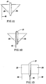
- the flexible panels 26 are generally rectangular in shape. Other shapes are also possible for the flexible panels 24 or portions thereof such as semi-circular (shown, e.g., in FIG. 7), trapezoidal (e.g. FIG. 10), or triangular (e.g. FIG. 8).
- the flexible panels 26 preferably have a length which is about 50% to about 90% of the length of the absorbent core 21. While the flexible panels 26 preferably have a length (measured in the axial direction) which is shorter than the length of the absorbent core 21, they may have a length which is longer than that of the absorbent core 21.
- the length of the flexible panels 26 need not be uniform from the attachment end of the panel 26 to the free end 27 of the panel 26.
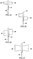
- FIG. 17, for example, shows one embodiment in which the length of the flexible panels 26 is non-uniform. Many other such non-uniform length embodiments are also possible.
- each flexible panel 26 refers to the distance from the attachment of the panel 26 to a side edge 25 of the absorbent core 21 to the unattached (or free) end 27 of the panel 26 (which end is sometimes also referred to as the "distal" end).
- the width of each flexible panel 26 or panels is preferably about 2 mm to about 30 mm, more preferably from about 3 mm to about 25 mm, most preferably from about 5 mm to about 20 mm.
- the width of a given flexible panel 26 need not be uniform along its length.
- FIGS. 10-12, for example, show some possible embodiments in which the width of the flexible panels 26 is not uniform along their length.
- the caliper of the flexible panel 26 or panels 26 is preferably less than or equal to about 3 mm, more preferably less than or equal to about 2 mm, and most preferably less than or equal to about 1 mm. Caliper measurements given herein were measured using an AMES gage with a 0.25 psig load and a 0.96 inch diameter foot. Those skilled in the art will recognize that if a 0.96 inch diameter foot is not appropriate for a particular sample size, the foot size may be varied while the load on the gauge is accordingly varied to maintain a confining pressure of 0.25 psig.
- the flexible panels 26 may be constructed from any suitable material. The materials listed above which are suitable for use in the absorbent core 21 are also acceptable for use in the flexible panels 26.
- the flexible panels 26 may be constructed of a tissue layer or layers.
- One suitable tissue is an airlaid tissue available from Fort Howard Tissue Company of Green Bay, Wisconsin, and having a basis weight of about 35 lbs./3000 sq. ft.
- Another suitable airlaid tissue is available from Merfin Hygenic Products, Ltd., of Delta, British Columbia, Canada, having a basis weight of about 61 lbs./3000 sq. ft. and having the designation grade number 176.
- FIGS. 1-3 One preferred embodiment for the construction of the tampon 20 of the present invention is shown in FIGS. 1-3.
- the tampon 20 shown in FIG. 2 comprises four flexible panels 26.
- the tampon pledget 28 is a rectangular batt of material which has two major surfaces 31 and two side surfaces 29.
- there are flexible panels 26 attached to the pledget 28 which are oriented in directions which are parallel and perpendicular to the major surfaces 31 of the pledget 28.
- FIG. 2 shows an example of flexible panels 26.
- the tampon pledget 28 is a rectangular batt of material which has two major surfaces 31 and two side surfaces 29.
- there are flexible panels 26 attached to the pledget 28 which are oriented in directions which are parallel and perpendicular to the major surfaces 31 of the pledget 28.
- a single piece of flexible panel material may be used. This material may extend through the interior of the pledget 28 or may be attached to either major surface 28 of the pledget. Of course, it is not necessary that a single piece of material extend all the way through or across the pledget 28, and a pair of flexible panels 26 may be individually attached to the pledget 28.
- FIG. 2 also shows a pair of flexible panels 26 each of which are attached to the pledget 28 in a direction which is generally perpendicular to the major surfaces 31 of the pledget 28.
- each panel 26 may be individually attached to the pledget, as shown in FIG. 2.
- at attachment tab 34 may be employed for such purpose.
- Any suitable attachment mechanism such as stitching 36 may be used to attach the tab 34, and consequently, the panels 26 to the pledget 28.
- joind encompasses configurations in which an element is directly secured to another element by affixing the element directly to the other element; configurations in which the element is indirectly secured to the other element by affixing the element to intermediate member(s) which in turn are affixed to the other element; and configurations in which one element is integral with another element; i.e., one element is essentially part of the other element.
- the flexible panels 26 may be joined to the pledget 26 and to the resulting absorbent core 21 (or directly to the pre-formed absorbent core) by any variety of means.
- the flexible panels 26 may be joined to the pledget 28 using any suitable adhesive.
- Such adhesive may extend continuously along the length of attachment or it may be applied in a "dotted" fashion at discrete intervals.
- the flexible panels 26 may be joined to the pledget 28 by stitching (such as stitching 36). Such stitching may use cotton or rayon thread.
- Other attachment mechanisms include thermally bonding (for example where the tampon core and panels have thermally bonded fibers or other thermally bonding materials incorporated therein), fusion bonding, or any other suitable means known in the art for joining such materials.
- the flexible panels 26 are attached to the side 25 of the absorbent core 21 of the tampon 20 and extend outwardly therefrom to a free end 27 which is unattached to the absorbent core 21.
- the flexible panels 26 may be biased slightly outward from the absorbent core 21 so as to tend to keep the panels 26 in contact with the inner surfaces of the vagina when the tampon 20 is in place. Additionally, the naturally moist surfaces of the vagina will have a tendency to adhere to the material comprising the flexible panels 26 further tending to keep them in contact with the surfaces of the vagina.
- the flexible panels 26 should be capable of a wide range of motion which is independent of other flexible panels 26 which may be present in the tampon 20.
- the flexible panels 26 may be either absorbent or non-absorbent. Preferably, the flexible panels 26 have at least some absorbency.
- the flexible panels 26 may have an advancing contact angle greater than the advancing contact angle of the absorbent core 21, such that fluid is preferentially directed toward and absorbed by the absorbent core 21.
- the flexible panels 26 may be treated to make them less absorbent than the absorbent core 21.
- the majority of the fluid absorbed and retained by the tampon 20 will ultimately be retained in the absorbent core 21.
- the major surface of the flexible panel 26 or panels may be plain, or it can be textured. It is also acceptable in embodiments with multiple to panels 26 to have both textured and non-textured panels (such as shown in FIG. 2 in which only one panel 26 is provided with texturing elements 38). Preferably, the flexible panels 26 are provided with texturing elements 38 and in more preferred embodiments, all of the flexible panels 26 are provided with such texturing elements 38.
- FIG. 2 an example of such a flexible panel 26 with a textured surface is shown in FIG. 2.
- the texturing can be provided through a variety of means, including a multiplicity of texturing elements 38 as is shown in FIG. 2. Such texturing may be provided by needle punching the surface of the flexible panel 26 to be textured. Additionally, the texturing elements 38 may be attached to either or both surfaces of a given flexible panel 26. Individual texturing elements 28 can be passed through the flexible panel 26 to extend outwardly from either major surface. Additionally, individual texturing elements 38 may be attached to an intermediate location between the major surfaces of a given flexible panel 26 or any combination of these locations.
- the flexible panels 26 preferably have major surfaces which comprises a plush or terry cloth type fabric which has a plurality of texturing elements 38 (such as outwardly extending fibers) extending outwardly therefrom.
- the texturing elements 38 may be randomly oriented or may be aligned in a particular direction or directions. Preferably these texturing elements 38 are generally perpendicular to the surfaces of the flexible panels 26. These texturing elements 38 penetrate into the rugosites in the vaginal cavity to intercept menses and reduce "by-pass" failures (failures from menses traveling in these rugosites and around the tampon).
- the texturing elements 38 may have a tendency to flex and/or orient themselves in response to forces exerted by the vaginal surfaces.
- the texturing elements 38 may be "looped" and attached to the surface of the flexible panel 26 at both ends. Suitable texturing elements may be formed from a single long fiber or a series of fibers which are punched in and out of the surface of the flexible panel 26 to form a plurality of loops. As noted, both sides, one side, or neither side of a given flexible panel 26 may be provided with texturing elements 38.
- the texturing elements 38 are preferably hydrophilic so as to facilitate the ready transfer of fluid from the vaginal surfaces to the main surface of the flexible panel 26 and, ultimately, to the absorbent core 21.
- the texturing elements 38 may also be configured to transfer fluid from the vaginal surfaces to the main surface of the flexible panel 26 and ultimately, to the absorbent core 21 through the use of a density gradient, hydrophilicity gradients, an osmotic driving force, capilarity, or a similar mechanism.
- Suitable materials for use in such fluid acquisition/transfer mechanisms are rayon (including, e.g., conventional, tri-lobed or multi-lobed rayon fibers), polyethylene, polypropylene, polyester, synthetic bi-component fibers, absorbent foams and combinations thereof, all of which fibers may be used either singly or in combination with other fibers are known in the art.
- Capillary channel fibers are a highly preferred fiber for the texturing elements 38.
- a preferred material for the flexible panels 26 is known as Cotton Interlock available from Empirical Manufacturing Co, Cincinnati, OH, as model no. C120. This is a textured cotton similar to a terry cloth or terry towel.
- the flexible panels 26 may optionally be provided with a cleansing or lubricating composition to facilitate insertion, removal, or for other purposes.
- the flexible panels 26 may have, and preferably do have, an incorporated mechanism to preferentially direct acquired fluid from the flexible panel 26 to the absorbent core 21.
- Such a mechanism may be any of those described above with respect to the texturing elements 38.
- the flexible panels 26 may be extensible or stretchable in one or more directions. This may be accomplished through the construction of flexible panels 26 from an inherently stretchable material or from a laminate where one or more of the layers is stretchable or extensible. Additionally, the material comprising the flexible panels 26 may be made extensible by a suitable mechanical process such as ring rolling or corrugating. The flexible panels 26 may also incorporate an extensible strip or element.
- the flexible panels 26 should have a strength and stiffness which make them both comfortable and able to dynamically adjust to the motion of the vagina.
- the flexible panels 26 have sufficient strength to prevent them from shredding and/or breaking which may leave pieces remaining in the wearer's vagina upon removal of the tampon 20.
- the flexible panels 26 should have sufficient flexibility to dynamically adjust to the motion of the vagina.
- a withdrawal cord 40 is typically attached to the tampon 20 for removal of the tampon after use.
- the withdrawal cord 48 may be attached in any suitable manner known in the art including sewing, adhesive attachment, or a combination of known bonding methods.
- the withdrawal cord 40 may be absorbent or non-absorbent, and is preferably non-absorbent.
- the withdrawal cord 40 may be attached to any suitable location on the tampon 20. In the embodiment shown in FIGS. 1-2, a single withdrawal cord 40 is attached to the second end 24 of the absorbent core 21.
- the withdrawal cord 40 is typically attached to the tampon pledget 28 while the pledget 28 is still uncompressed as shown in FIG. 2.
- the withdrawal cord 40 may be attached along the entire length one major surface of the pledget 28 and hang free from one end, such as the second end 24.
- the tampon may be provided with a flexible panel attached withdrawal cord 46, such as shown in FIG. 11.
- the withdrawal cord 26 may be attached to any suitable location on one of the flexible panels 26.
- a panel attached withdrawal cord 26 is attached proximate the free end of the flexible panel 26.
- FIG. 12 shows another variation in which the withdrawal cord is attached to the absorbent core 21 portion of the tampon, but is attached to the first end 22 (or insertion end).
- Such an attachment location allows the user to pull on the withdrawal cord 40 after insertion of the tampon for post-insertion rotation or other manipulation.
- Some users will prefer the tampon to be disposed in a generally horizontal relationship in the vaginal canal rather than a primarily vertical one.
- some users will use an insertion end attached withdrawal cord 40 to completely rotate the tampon post insertion. Such complete rotation may assist the flexible panels 26 in extending to more effectively cover the surfaces of the vaginal interior.
- the tampon of the present invention may also be provided with flexible panel manipulation cords 48 such as shown in FIG. 13. While such panel manipulation cords are optional, any flexible panel 26 provided on the tampon may have a cord attached to any suitable location. Such cords may be used by the user to control the movement of the flexible panels 26 after insertion of the tampon itself.
- the tampon pledget 28 is typically compressed and heat conditioned in any suitable conventional manner. Pressures and temperatures suitable for this purpose are well known in the art. Typically, the pledget 28 is compressed in both the radial and axial direction using any means well known in the art. While a variety of techniques are known and acceptable for these purposes, a modified tampon compressor machine available from Hauni Machines, Richmond, VA, is suitable. Preferably, the flexible panels 26 are attached to the uncompressed pledget 28 as shown in FIG. 2. The pledget 28 may then be compressed into the absorbent core 21 as shown in FIG. 3. FIG.
- FIG 3 shows a series of compression dies 44 provided with narrow axial slits which allow compression of the absorbent core 21 without compressing the flexible panels 26. It may also be desirable in some embodiments to attach the flexible panels 26 to the absorbent core 21 after compression of such absorbent core.
- the tampon 20 of the present invention may be inserted digitally or through the use of an applicator. If the tampon 20 is to be used for digital insertion, it may be desirable to form the pledget from a layer of absorbent material which has been rolled into a cylindrical shape. Flexible panels 26 could be attached to such a layer in any suitable manner. For example, the attachment tabs 34 shown in FIG. 2 may be used to attach one or more flexible panels 26 to a rolled pledget.
- any of the currently available tampon applicators may also be used for insertion of the tampon of the present invention.
- Such applicators of typically a "tube and plunger" type arrangement and may be plastic, paper, or other suitable material. Additionally, a "compact” type applicator is also suitable.
- the flexible nature of the flexible panels 26 allows them to reside with the tampon in the applicator tube along with the absorbent core 21 portion of the tampon. The applicator plunger will push the absorbent core 21 out of the applicator due to the compressed nature of the core.
- the flexible extensions 26 are then available to begin collecting fluid immediately after insertion from their generally uncompressed state.
- the tampon of the present invention has at least one flexible panel 26.
- the tampon of the present invention has at least one flexible panel 26.
- FIG. 4 shows one example of a tampon of the present invention having two panels.
- FIG. 5 shows three such flexible panels.
- FIG. 6 shows an embodiment having eight flexible panels 26.
- the panels 26 are approximately evenly spaced around the absorbent core21 although this is not required.
- FIGS. 7-10 and 14-17 show a variety of examples of the variations which are possible for the flexible extensions 26. These examples are not exhaustive and other variations are also possible.
Claims (21)
- Katamnesetampon (20) mit einer Länge, die in einer axialen Richtung orientiert ist, wobei der Tampon umfaßt:dadurch gekennzeichnet, daß die Breite des wenigstens einen flexiblen Feldes (26) von 2 mm bis 30 mm beträgt und wobei die Breite des wenigstens einen flexiblen Feldes (26) die Dicke des wenigstens einen flexiblen Feldes (26) übersteigt, wobei das wenigstens eine flexible Feld (26) eine erste Dichte hat und der zentrale absorbierende Kern (21) eine zweite Dichte hat, wobei die zweite Dichte größer ist als die erste Dichte.einen zentralen absorbierenden Kern (21) mit einem ersten Ende (22), einem zweiten Ende (24), der dem ersten Ende (22) entgegen gesetzt ist, und einer Seitenoberfläche (25), die sich zwischen dem ersten Ende (22) und dem zweiten Ende (24) erstreckt, wobei das erste (22) mit einem Einführende des Tampons korrespondiert, wobei die Seitenoberfläche (25) in einer Richtung im wesentlichen parallel zur einer sich längs erstreckenden zentralen Achse orientiert ist, wobei der zentrale absorbierende Kern aus einem absorbierenden Material konstruiert ist, der in eine selbst haltende Form komprimiert ist;wenigstens einem flexiblen Feld (26), das mit dem zentralen absorbierenden Kern (21) entlang wenigstens eines Bereichs der Seitenoberfläche (25) verbunden ist, wobei sich wenigstens ein flexibles Feld (26) von dem zentralen absorbierenden Kern (21) zu einem freien Ende (27) nach außen erstreckt, wobei wenigstens ein flexibles Feld (26) eine Länge hat, die sich in einer axialen Richtung orientiert und eine Breite hat, die sich von der Seitenoberfläche (25) zu dem freien Ende (27) erstreckt und in einer Richtung rechtwinklig zu der Länge orientiert ist, und wobei das wenigstens eine flexible Feld (26) eine Dicke hat, die in einer Richtung rechtwinklig sowohl zur Länge als auch zur Breite orientiert istund einer Herausziehschnur (40), die mit dem Tampon (20) verbunden ist, und sich von diesem erstreckt,
- Tampon nach Anspruch 1, in welchem das wenigstens eine flexible Feld (26) im wesentlichen rechtwinklig ist.
- Tampon nach Anspruch 1, in welchem der Tampon zwischen 2 und 20 flexible Felder (26) umfaßt.
- Tampon nach Anspruch 3, in welchem der Tampon zwischen 2 und 4 flexible Felder (26) umfaßt.
- Tampon nach Anspruch 1, in welchem das wenigstens eine flexible Feld (26) im wesentlichen dreieckig ist.
- Tampon nach Anspruch 1, in welchem das wenigstens eine flexible Feld (26) im wesentlichen halbkreisförmig ist.
- Tampon nach Anspruch 1, in welchem das wenigstens eine flexible Feld (26) im wesentlichen trapezoidförmig ist.
- Tampon nach Anspruch 1, in welchem die Herausziehschnur (40) an dem zentralen absorbierenden Kern (21) angebracht ist.
- Tampon nach Anspruch 8, in welchem die Herausziehschnur (40) an dem ersten Ende (22) des zentralen absorbierenden Kerns (21) angebracht ist.
- Tampon nach Anspruch 8, in welchem die Herausziehschnur (40) an dem zweiten Ende des zentralen absorbierenden Kerns (21) angebracht ist.
- Tampon nach Anspruch 1, in welchem die Herausziehschnur (40) an einem des wenigstens einen flexiblen Feldes (26) angebracht ist, und dadurch der Herausziehschnur (40) erlaubt, auch zur Manipulation des wenigstens einen flexiblen Feldes (26) verwendet zu werden.
- Tampon nach Anspruch 1, ferner mit einer zweiten Schnur, die an dem Tampon zusätzlich zu der Herausziehschnur (40) angebracht ist, wobei wenigstens der Herausziehschnur (40) und der zweiten Schnur in der Lage ist, für eine Manipulation nach Einführung des Tampons geeignet ist.
- Tampon nach Anspruch 1, in welchem das wenigstens eine flexible Feld (26) wenigstens teilweise absorbierend ist.
- Tampon nach Anspruch 1, in welchem das wenigstens eine flexible Feld (26) mit einem Antriebsmechanismus versehen ist, um ein Fluid zu dem zentralen absorbierenden Kern (21) des Tampons hin abzulenken.
- Tampon nach Anspruch 14, in welchem der Antriebsmechanismus durch die Verwendung von Kapillarkanalfasern geschaffen ist.
- Tampon nach Anspruch 14, in welchem der Antriebsmechanismus durch die Verwendung einer Regulierung der Kapillargröße geschaffen ist.
- Tampon nach Anspruch 16, in welchem die Regulierung der Kapillargröße durch die Verwendung eines Dichtegradienten geschaffen ist.
- Tampon nach Anspruch 14, in welchem der Antriebsmechanismus durch die Verwendung einer osmotischen Antriebskraft geschaffen ist.
- Tampon nach Anspruch 14, in welchem der Antriebsmechanismus durch die Verwendung eines Hydrophilizitätsgradienten geschaffen ist.
- Tampon nach Anspruch 1, in welchem der Tampon aus Rayon zusammen gesetzt ist.
- Tampon nach Anspruch 1, in welchem der Tampon aus Baumwolle zusammen gesetzt ist.
Applications Claiming Priority (9)
| Application Number | Priority Date | Filing Date | Title |
|---|---|---|---|
| US09/124,351 US6095998A (en) | 1998-07-29 | 1998-07-29 | Expandable bag tampon and spreading tampon applicator therefor |
| US09/124,407 US6302861B2 (en) | 1998-07-29 | 1998-07-29 | Spreading tampon applicator |
| US124351 | 1998-07-29 | ||
| US124407 | 1998-07-29 | ||
| US177221 | 1998-10-22 | ||
| US09/177,221 US6358235B1 (en) | 1998-07-29 | 1998-10-22 | Soft conformable hollow bag tampon |
| US09/287,994 US6206867B1 (en) | 1998-07-29 | 1999-04-08 | Tampon with flexible panels |
| US287994 | 1999-04-08 | ||
| PCT/US1999/017157 WO2000006070A1 (en) | 1998-07-29 | 1999-07-29 | Tampon with flexible panels |
Publications (2)
| Publication Number | Publication Date |
|---|---|
| EP1100424A1 EP1100424A1 (de) | 2001-05-23 |
| EP1100424B1 true EP1100424B1 (de) | 2003-04-23 |
Family
ID=27494535
Family Applications (1)
| Application Number | Title | Priority Date | Filing Date |
|---|---|---|---|
| EP99938856A Revoked EP1100424B1 (de) | 1998-07-29 | 1999-07-29 | Tampon mit flexiblen flügeln |
Country Status (12)
| Country | Link |
|---|---|
| US (1) | US6206867B1 (de) |
| EP (1) | EP1100424B1 (de) |
| JP (1) | JP4459446B2 (de) |
| KR (1) | KR20010072058A (de) |
| CN (1) | CN1310602A (de) |
| AT (1) | ATE238017T1 (de) |
| AU (1) | AU748284B2 (de) |
| BR (1) | BR9912452A (de) |
| CA (1) | CA2336394A1 (de) |
| DE (1) | DE69907207T2 (de) |
| MX (1) | MXPA00012996A (de) |
| WO (1) | WO2000006070A1 (de) |
Families Citing this family (58)
| Publication number | Priority date | Publication date | Assignee | Title |
|---|---|---|---|---|
| US20030004435A1 (en) * | 2001-06-28 | 2003-01-02 | Crawford Paul G. | Device for collecting cellular & DNA specimens |
| US7727208B2 (en) | 2002-09-12 | 2010-06-01 | Playtex Products, Inc. | Ergonomic tampon applicator |
| US8197434B2 (en) | 2003-05-02 | 2012-06-12 | Playtex Products, Inc. | Tampon assembly having shaped pledget |
| US9192522B2 (en) * | 2003-05-02 | 2015-11-24 | Eveready Battery Company, Inc. | Tampon assembly having shaped pledget |
| US7214218B2 (en) * | 2003-11-21 | 2007-05-08 | The Procter & Gamble Company | Tampon with raised portions having multiple widths |
| EP1547554A1 (de) * | 2003-12-22 | 2005-06-29 | Ontex N.V. | Absorbierender Artikel |
| DE602004015715D1 (de) * | 2004-02-05 | 2008-09-25 | Procter & Gamble | Tampon mit versetzten Rillen |
| AU2011206948B2 (en) * | 2004-05-14 | 2012-04-05 | Johnson & Johnson Consumer Inc. | Intravaginal device with fluid transport plates |
| CN1980621B (zh) * | 2004-05-14 | 2010-11-10 | 强生消费者公司 | 包装阴道内装置的方法 |
| US8247642B2 (en) | 2004-05-14 | 2012-08-21 | Mcneil-Ppc, Inc. | Fluid management device with fluid transport element for use within a body |
| US8864640B2 (en) * | 2004-05-14 | 2014-10-21 | Mcneil-Ppc, Inc. | Methods of packaging intravaginal device |
| AR048846A1 (es) * | 2004-05-14 | 2006-05-31 | Johnson & Johnson Consumer | Metodo para utilizar un dispositivo intravaginal con planchas de transporte de fluidos |
| WO2005112856A1 (en) * | 2004-05-14 | 2005-12-01 | Johnson & Johnson Consumer Companies, Inc. | Intravaginal device with fluid transport plates |
| US20050256484A1 (en) * | 2004-05-14 | 2005-11-17 | Chase David J | Method of using an intravaginal device with fluid transport plates |
| US7618403B2 (en) | 2004-05-14 | 2009-11-17 | Mcneil-Ppc, Inc. | Fluid management device with fluid transport element for use within a body |
| US20050277904A1 (en) * | 2004-05-14 | 2005-12-15 | Chase David J | Tampon with flexible panels |
| US20050256485A1 (en) * | 2004-05-14 | 2005-11-17 | Samuel Carasso | Method of using intravaginal device with fluid transport plates |
| US8480833B2 (en) * | 2004-05-14 | 2013-07-09 | Mcneil-Ppc, Inc. | Intravaginal device with fluid transport plates and methods of making |
| AU2011206947B2 (en) * | 2004-05-14 | 2013-01-24 | Johnson & Johnson Consumer Inc. | Method of using intravaginal device with fluid transport plates |
| US7845380B2 (en) * | 2004-05-14 | 2010-12-07 | Mcneil-Ppc, Inc. | Intravaginal device with fluid transport plates |
| AU2011207948B2 (en) * | 2004-05-14 | 2012-07-12 | Johnson & Johnson Consumer Inc. | Intravaginal device with fluid transport plates and methods of making |
| US8653322B2 (en) * | 2004-05-14 | 2014-02-18 | Mcneil-Ppc, Inc. | Intravaginal device with fluid transport plates |
| US8702670B2 (en) * | 2004-06-30 | 2014-04-22 | Mcneil-Ppc, Inc. | Intravaginal device with controlled expansion |
| EP1683503B1 (de) * | 2005-01-19 | 2011-10-05 | Ontex International N.V. | Tampon |
| SI1695680T1 (sl) * | 2005-02-24 | 2007-12-31 | Ontex Hygieneartikel Deutschla | Vstavljalec tamponov |
| EP1704841B1 (de) * | 2005-03-25 | 2008-09-17 | Georgia-Pacific France | Tampon und Applikatoranordnung |
| US20060264870A1 (en) * | 2005-05-23 | 2006-11-23 | Carstens Jerry E | System comprising thong-shaped holder and absorbent article |
| US7867211B2 (en) * | 2005-05-23 | 2011-01-11 | Rusl, Llc | System comprising thong-shaped holder and absorbent article |
| US20060264871A1 (en) * | 2005-05-23 | 2006-11-23 | Carstens Jerry E | System comprising thong-shaped holder and absorbent article |
| US20060264868A1 (en) * | 2005-05-23 | 2006-11-23 | Carstens Jerry E | System comprising thong-shaped holder and article with sensor |
| US20070142816A1 (en) * | 2005-12-19 | 2007-06-21 | Carstens Jerry E | Absorbent article and system comprising thong-shaped holder |
| US20060264879A1 (en) * | 2005-05-23 | 2006-11-23 | Carstens Jerry E | System comprising thong-shaped holder and absorbent articles |
| US7537587B2 (en) * | 2005-05-23 | 2009-05-26 | Rusl, Llc | System comprising thong-shaped holder and absorbent article |
| US20060264872A1 (en) * | 2005-05-23 | 2006-11-23 | Carstens Jerry E | System comprising thong-shaped holder and absorbent article |
| US7481801B2 (en) * | 2005-05-23 | 2009-01-27 | Rusl, Llc | System comprising thong-shaped holder and absorbent article |
| US20060264865A1 (en) * | 2005-05-23 | 2006-11-23 | Carstens Jerry E | System comprising thong-shaped holder and absorbent interlabial article |
| US20060264873A1 (en) * | 2005-05-23 | 2006-11-23 | Carstens Jerry E | System comprising thong-shaped holder and absorbent article |
| US7458961B2 (en) | 2005-05-23 | 2008-12-02 | Rusl, Llc | Thong-shaped holder for use with absorbent article |
| US7462173B2 (en) * | 2005-05-23 | 2008-12-09 | Rusl, Llc | System comprising thong-shaped holder and absorbent article |
| DE102005042012B4 (de) * | 2005-09-02 | 2010-06-10 | Drescher, Rüdiger | Tampon |
| CN101378711B (zh) | 2006-02-02 | 2013-01-09 | 奥特斯联合有限公司 | 卫生栓 |
| KR101154134B1 (ko) | 2006-06-12 | 2012-06-14 | 플레이텍스 프로덕츠, 엘엘씨. | 거즈의 적절한 신체내 위치를 제공하는 탐폰 어셈블리 |
| PL2040657T3 (pl) * | 2006-06-30 | 2014-11-28 | Mcneil Ppc Inc | Sposób i urządzenie do wytwarzania urządzenia dopochwowego z płytkami do przenoszenia płynu |
| US7554384B2 (en) * | 2006-06-30 | 2009-06-30 | Intel Corporation | Methods and arrangements for generating a control signal for a power converter |
| US8147471B2 (en) * | 2006-09-11 | 2012-04-03 | Merimont Us | Sanitary napkin with braid |
| WO2008057581A1 (en) * | 2006-11-08 | 2008-05-15 | Playtex Products, Inc. | Tampon pledget for increased bypass leakage protection |
| WO2008095937A2 (en) * | 2007-02-09 | 2008-08-14 | Ontex Hygieneartikel Deutschland Gmbh | Tampon |
| US8597267B2 (en) * | 2007-04-18 | 2013-12-03 | The Procter & Gamble Company | Tampon having at least one physical discontinuity |
| EP2355763A2 (de) * | 2008-11-13 | 2011-08-17 | Ontex Hygieneartikel Deutschland GmbH | Tampon mit perforierter aussenabdeckung |
| US20110238028A1 (en) * | 2008-12-16 | 2011-09-29 | Ontex Hygieneartikel Deutschland Gmbh | Tampon with modified constricted withdrawal end |
| WO2012004315A1 (en) | 2010-07-09 | 2012-01-12 | Ontex Hygieneartikel Deutschland Gmbh | Press and method for producing absorbent article |
| GB201201645D0 (en) * | 2012-01-31 | 2012-03-14 | Ge Healthcare Ltd | Improvements in and relating to biological sample collection |
| CA2955201A1 (en) | 2014-07-18 | 2016-01-21 | The Procter & Gamble Company | Absorbent catamenial tampon |
| US11096677B2 (en) * | 2014-09-18 | 2021-08-24 | Covidien Lp | Regions of varying physical properties in a compressible cell collection device |
| US11071656B2 (en) | 2016-11-07 | 2021-07-27 | The Procter & Gamble Company | Tampon and method for making the same |
| WO2018085825A1 (en) | 2016-11-07 | 2018-05-11 | The Procter & Gamble Company | Tampon |
| US11439803B2 (en) | 2019-01-31 | 2022-09-13 | Niva Medtech LLC | Medicant applicator |
| USD908211S1 (en) | 2020-01-31 | 2021-01-19 | Niva Medtech LLC | Medicant applicator |
Family Cites Families (20)
| Publication number | Priority date | Publication date | Assignee | Title |
|---|---|---|---|---|
| US3371666A (en) * | 1965-01-26 | 1968-03-05 | Tampax Inc | Absorbent device |
| US3431909A (en) | 1965-11-04 | 1969-03-11 | Scott Paper Co | Uncompressed tampon and applicator |
| US3512528A (en) | 1967-05-29 | 1970-05-19 | Kimberly Clark Co | Expandable tampon |
| US3593715A (en) * | 1968-11-05 | 1971-07-20 | Tampax Inc | Tampon |
| US3618605A (en) | 1969-11-12 | 1971-11-09 | Jacob A Glassman | Catamenial tampon |
| US3766921A (en) | 1971-08-18 | 1973-10-23 | Procter & Gamble | Proximal apex tampon |
| US3749094A (en) | 1971-08-18 | 1973-07-31 | Procter & Gamble | Tampon with string attached to its proximal end |
| US3794029A (en) | 1971-08-18 | 1974-02-26 | Procter & Gamble | Compliant conformable tampon |
| US3857395A (en) | 1974-01-28 | 1974-12-31 | Kimberly Clark Co | Conformable absorbent tampon and inserter device therefor |
| US4212301A (en) | 1978-08-14 | 1980-07-15 | Kimberly-Clark Corporation | Digital tampon |
| US4627849A (en) * | 1982-06-30 | 1986-12-09 | Kimberly-Clark Corporation | Tampon |
| US5403300A (en) * | 1989-03-31 | 1995-04-04 | Smith & Nephew P.L.C. | Tampons |
| US5584827A (en) * | 1992-05-18 | 1996-12-17 | Ultracell Medical Technologies, Inc | Nasal-packing article |
| US5273521A (en) * | 1992-08-26 | 1993-12-28 | Peiler Frances K | Tampon applicator for delivery of a medicament |
| DE4304505C2 (de) * | 1993-02-15 | 1995-05-18 | Johnson & Johnson Gmbh | Tampon, insbesondere für die Frauenhygiene, sowie Verfahren und Vorrichtung zur Herstellung desselben |
| DE4325220C2 (de) * | 1993-07-28 | 1996-08-29 | Ruggli Ag Karl | Tampon sowie Verfahren und Vorrichtung zu seiner Herstellung |
| US5665452A (en) * | 1994-03-03 | 1997-09-09 | The Procter & Gamble Company | Three-dimensional, macroscopically expanded, apertured laminate webs |
| CA2149498A1 (en) * | 1994-05-31 | 1995-12-01 | Theodore A. Foley | Vaginal moisture balanced tampon and process |
| US5624423A (en) * | 1994-11-30 | 1997-04-29 | Kimberly-Clark Corporation | Absorbent article having barrier means and medial bulge |
| US6036666A (en) * | 1996-10-09 | 2000-03-14 | Peiler; Frances K. | Tampon applicator |
-
1999
- 1999-04-08 US US09/287,994 patent/US6206867B1/en not_active Expired - Lifetime
- 1999-07-29 CN CN99808895A patent/CN1310602A/zh active Pending
- 1999-07-29 JP JP2000561927A patent/JP4459446B2/ja not_active Expired - Fee Related
- 1999-07-29 KR KR1020017001068A patent/KR20010072058A/ko not_active Application Discontinuation
- 1999-07-29 AU AU53250/99A patent/AU748284B2/en not_active Ceased
- 1999-07-29 BR BR9912452-1A patent/BR9912452A/pt not_active IP Right Cessation
- 1999-07-29 AT AT99938856T patent/ATE238017T1/de not_active IP Right Cessation
- 1999-07-29 CA CA002336394A patent/CA2336394A1/en not_active Abandoned
- 1999-07-29 WO PCT/US1999/017157 patent/WO2000006070A1/en not_active Application Discontinuation
- 1999-07-29 EP EP99938856A patent/EP1100424B1/de not_active Revoked
- 1999-07-29 DE DE69907207T patent/DE69907207T2/de not_active Revoked
-
2000
- 2000-12-20 MX MXPA00012996 patent/MXPA00012996A/es unknown
Also Published As
| Publication number | Publication date |
|---|---|
| MXPA00012996A (es) | 2001-05-01 |
| EP1100424A1 (de) | 2001-05-23 |
| AU5325099A (en) | 2000-02-21 |
| KR20010072058A (ko) | 2001-07-31 |
| DE69907207T2 (de) | 2003-11-13 |
| AU748284B2 (en) | 2002-05-30 |
| CN1310602A (zh) | 2001-08-29 |
| DE69907207D1 (de) | 2003-05-28 |
| JP4459446B2 (ja) | 2010-04-28 |
| ATE238017T1 (de) | 2003-05-15 |
| BR9912452A (pt) | 2001-10-02 |
| JP2002521133A (ja) | 2002-07-16 |
| WO2000006070A1 (en) | 2000-02-10 |
| US6206867B1 (en) | 2001-03-27 |
| CA2336394A1 (en) | 2000-02-10 |
Similar Documents
| Publication | Publication Date | Title |
|---|---|---|
| EP1100424B1 (de) | Tampon mit flexiblen flügeln | |
| EP1171072B1 (de) | Tampon mit einer erhöhten lecksicherung | |
| ZA200007362B (en) | Tampon with flexible panels. | |
| EP2136755B1 (de) | Tampon mit mindestens einer physischen unterbrechung | |
| EP1542634B2 (de) | Tampon mit sauberem erscheinungsbild nach dem gebrauch | |
| EP1928382B1 (de) | Tampon mit verpackung und herstellungsverfahren | |
| EP2114332B1 (de) | Selbstausrichtender tampon mit verbessertem aspektverhältnis | |
| WO2005051257A2 (en) | Tampon with recessed portions | |
| WO2005051266A2 (en) | Tampon with raised portions | |
| US20050055003A1 (en) | Absorbent tampon comprising a secondary absorbent member attached to the outer surface | |
| CA2466973A1 (en) | Tampon with a blended non-woven overwrap | |
| WO2005044165A1 (en) | Tampon with enhanced leakage protection | |
| US20150157511A1 (en) | Feminine hygiene device with withdrawal member | |
| AU2003271375A1 (en) | Tampon with enhanced leakage protection | |
| ZA200107828B (en) | Tampon with enhanced leakage protection. |
Legal Events
| Date | Code | Title | Description |
|---|---|---|---|
| PUAI | Public reference made under article 153(3) epc to a published international application that has entered the european phase |
Free format text: ORIGINAL CODE: 0009012 |
|
| 17P | Request for examination filed |
Effective date: 20010115 |
|
| AK | Designated contracting states |
Kind code of ref document: A1 Designated state(s): AT BE CH CY DE DK ES FI FR GB GR IE IT LI LU MC NL PT SE |
|
| 17Q | First examination report despatched |
Effective date: 20010927 |
|
| GRAG | Despatch of communication of intention to grant |
Free format text: ORIGINAL CODE: EPIDOS AGRA |
|
| GRAG | Despatch of communication of intention to grant |
Free format text: ORIGINAL CODE: EPIDOS AGRA |
|
| GRAH | Despatch of communication of intention to grant a patent |
Free format text: ORIGINAL CODE: EPIDOS IGRA |
|
| GRAH | Despatch of communication of intention to grant a patent |
Free format text: ORIGINAL CODE: EPIDOS IGRA |
|
| GRAA | (expected) grant |
Free format text: ORIGINAL CODE: 0009210 |
|
| AK | Designated contracting states |
Designated state(s): AT BE CH CY DE DK ES FI FR GB GR IE IT LI LU NL PT SE |
|
| PG25 | Lapsed in a contracting state [announced via postgrant information from national office to epo] |
Ref country code: NL Free format text: LAPSE BECAUSE OF FAILURE TO SUBMIT A TRANSLATION OF THE DESCRIPTION OR TO PAY THE FEE WITHIN THE PRESCRIBED TIME-LIMIT Effective date: 20030423 Ref country code: LI Free format text: LAPSE BECAUSE OF FAILURE TO SUBMIT A TRANSLATION OF THE DESCRIPTION OR TO PAY THE FEE WITHIN THE PRESCRIBED TIME-LIMIT Effective date: 20030423 Ref country code: IT Free format text: LAPSE BECAUSE OF FAILURE TO SUBMIT A TRANSLATION OF THE DESCRIPTION OR TO PAY THE FEE WITHIN THE PRESCRIBED TIME-LIMIT;WARNING: LAPSES OF ITALIAN PATENTS WITH EFFECTIVE DATE BEFORE 2007 MAY HAVE OCCURRED AT ANY TIME BEFORE 2007. THE CORRECT EFFECTIVE DATE MAY BE DIFFERENT FROM THE ONE RECORDED. Effective date: 20030423 Ref country code: FI Free format text: LAPSE BECAUSE OF FAILURE TO SUBMIT A TRANSLATION OF THE DESCRIPTION OR TO PAY THE FEE WITHIN THE PRESCRIBED TIME-LIMIT Effective date: 20030423 Ref country code: CH Free format text: LAPSE BECAUSE OF FAILURE TO SUBMIT A TRANSLATION OF THE DESCRIPTION OR TO PAY THE FEE WITHIN THE PRESCRIBED TIME-LIMIT Effective date: 20030423 Ref country code: BE Free format text: LAPSE BECAUSE OF FAILURE TO SUBMIT A TRANSLATION OF THE DESCRIPTION OR TO PAY THE FEE WITHIN THE PRESCRIBED TIME-LIMIT Effective date: 20030423 Ref country code: AT Free format text: LAPSE BECAUSE OF FAILURE TO SUBMIT A TRANSLATION OF THE DESCRIPTION OR TO PAY THE FEE WITHIN THE PRESCRIBED TIME-LIMIT Effective date: 20030423 |
|
| REG | Reference to a national code |
Ref country code: GB Ref legal event code: FG4D |
|
| REG | Reference to a national code |
Ref country code: CH Ref legal event code: EP |
|
| REF | Corresponds to: |
Ref document number: 69907207 Country of ref document: DE Date of ref document: 20030528 Kind code of ref document: P |
|
| REG | Reference to a national code |
Ref country code: IE Ref legal event code: FG4D |
|
| PG25 | Lapsed in a contracting state [announced via postgrant information from national office to epo] |
Ref country code: SE Free format text: LAPSE BECAUSE OF FAILURE TO SUBMIT A TRANSLATION OF THE DESCRIPTION OR TO PAY THE FEE WITHIN THE PRESCRIBED TIME-LIMIT Effective date: 20030723 Ref country code: PT Free format text: LAPSE BECAUSE OF FAILURE TO SUBMIT A TRANSLATION OF THE DESCRIPTION OR TO PAY THE FEE WITHIN THE PRESCRIBED TIME-LIMIT Effective date: 20030723 Ref country code: GR Free format text: LAPSE BECAUSE OF FAILURE TO SUBMIT A TRANSLATION OF THE DESCRIPTION OR TO PAY THE FEE WITHIN THE PRESCRIBED TIME-LIMIT Effective date: 20030723 Ref country code: DK Free format text: LAPSE BECAUSE OF FAILURE TO SUBMIT A TRANSLATION OF THE DESCRIPTION OR TO PAY THE FEE WITHIN THE PRESCRIBED TIME-LIMIT Effective date: 20030723 |
|
| PG25 | Lapsed in a contracting state [announced via postgrant information from national office to epo] |
Ref country code: LU Free format text: LAPSE BECAUSE OF NON-PAYMENT OF DUE FEES Effective date: 20030729 Ref country code: IE Free format text: LAPSE BECAUSE OF NON-PAYMENT OF DUE FEES Effective date: 20030729 Ref country code: CY Free format text: LAPSE BECAUSE OF FAILURE TO SUBMIT A TRANSLATION OF THE DESCRIPTION OR TO PAY THE FEE WITHIN THE PRESCRIBED TIME-LIMIT Effective date: 20030729 |
|
| NLV1 | Nl: lapsed or annulled due to failure to fulfill the requirements of art. 29p and 29m of the patents act | ||
| ET | Fr: translation filed | ||
| PG25 | Lapsed in a contracting state [announced via postgrant information from national office to epo] |
Ref country code: ES Free format text: LAPSE BECAUSE OF FAILURE TO SUBMIT A TRANSLATION OF THE DESCRIPTION OR TO PAY THE FEE WITHIN THE PRESCRIBED TIME-LIMIT Effective date: 20031030 |
|
| REG | Reference to a national code |
Ref country code: CH Ref legal event code: PL |
|
| PLBQ | Unpublished change to opponent data |
Free format text: ORIGINAL CODE: EPIDOS OPPO |
|
| PLBI | Opposition filed |
Free format text: ORIGINAL CODE: 0009260 |
|
| PLAX | Notice of opposition and request to file observation + time limit sent |
Free format text: ORIGINAL CODE: EPIDOSNOBS2 |
|
| 26 | Opposition filed |
Opponent name: JOHNSON & JOHNSON CONSUMER COMPANIES, INC. Effective date: 20040123 |
|
| REG | Reference to a national code |
Ref country code: IE Ref legal event code: MM4A |
|
| PLAX | Notice of opposition and request to file observation + time limit sent |
Free format text: ORIGINAL CODE: EPIDOSNOBS2 |
|
| PLAX | Notice of opposition and request to file observation + time limit sent |
Free format text: ORIGINAL CODE: EPIDOSNOBS2 |
|
| PLBB | Reply of patent proprietor to notice(s) of opposition received |
Free format text: ORIGINAL CODE: EPIDOSNOBS3 |
|
| PGFP | Annual fee paid to national office [announced via postgrant information from national office to epo] |
Ref country code: DE Payment date: 20070731 Year of fee payment: 9 |
|
| PGFP | Annual fee paid to national office [announced via postgrant information from national office to epo] |
Ref country code: GB Payment date: 20070618 Year of fee payment: 9 |
|
| RDAF | Communication despatched that patent is revoked |
Free format text: ORIGINAL CODE: EPIDOSNREV1 |
|
| REG | Reference to a national code |
Ref country code: HK Ref legal event code: WD Ref document number: 1038173 Country of ref document: HK |
|
| RDAG | Patent revoked |
Free format text: ORIGINAL CODE: 0009271 |
|
| STAA | Information on the status of an ep patent application or granted ep patent |
Free format text: STATUS: PATENT REVOKED |
|
| PGFP | Annual fee paid to national office [announced via postgrant information from national office to epo] |
Ref country code: FR Payment date: 20070706 Year of fee payment: 9 |
|
| 27W | Patent revoked |
Effective date: 20071217 |
|
| GBPR | Gb: patent revoked under art. 102 of the ep convention designating the uk as contracting state |
Effective date: 20071217 |