EP1100138A1 - Pile et support de fixation de la pile - Google Patents
Pile et support de fixation de la pile Download PDFInfo
- Publication number
- EP1100138A1 EP1100138A1 EP99811043A EP99811043A EP1100138A1 EP 1100138 A1 EP1100138 A1 EP 1100138A1 EP 99811043 A EP99811043 A EP 99811043A EP 99811043 A EP99811043 A EP 99811043A EP 1100138 A1 EP1100138 A1 EP 1100138A1
- Authority
- EP
- European Patent Office
- Prior art keywords
- battery
- housing
- winding
- cavity
- battery according
- Prior art date
- Legal status (The legal status is an assumption and is not a legal conclusion. Google has not performed a legal analysis and makes no representation as to the accuracy of the status listed.)
- Granted
Links
Images


Classifications
-
- H—ELECTRICITY
- H01—ELECTRIC ELEMENTS
- H01M—PROCESSES OR MEANS, e.g. BATTERIES, FOR THE DIRECT CONVERSION OF CHEMICAL ENERGY INTO ELECTRICAL ENERGY
- H01M4/00—Electrodes
- H01M4/02—Electrodes composed of, or comprising, active material
- H01M4/64—Carriers or collectors
- H01M4/70—Carriers or collectors characterised by shape or form
-
- H—ELECTRICITY
- H01—ELECTRIC ELEMENTS
- H01M—PROCESSES OR MEANS, e.g. BATTERIES, FOR THE DIRECT CONVERSION OF CHEMICAL ENERGY INTO ELECTRICAL ENERGY
- H01M6/00—Primary cells; Manufacture thereof
- H01M6/04—Cells with aqueous electrolyte
- H01M6/06—Dry cells, i.e. cells wherein the electrolyte is rendered non-fluid
- H01M6/10—Dry cells, i.e. cells wherein the electrolyte is rendered non-fluid with wound or folded electrodes
Definitions
- the invention relates to a battery with a housing with at least two power connections, and a holder for such a battery.
- High energy densities can be achieved with wound batteries, e.g. in the EP 0 144 757 or US 5,556,722.
- a sealed case is a Wrapped ("jelly roll") with an active cathode and an active anode tape.
- the coils, which are coiled spirally, are separated by a separator electrically separated, a liquid electrolyte or a polymer serving as an ion conductor.
- Electrical conductors connect the tapes to power connections arranged on the outside of the housing (Minus and plus poles of the battery).
- the object of the invention is to provide a battery of the type mentioned that the Device manufacturer offers space saving.
- At least one power connector is formed in a cavity, which in the battery case protrudes.
- Another advantage is that an integrated plug contact is available in this way can be put, which has excellent properties, as with conventional Spring contacts can not be reached.
- the cavity is preferably elongated or tubular. That means he has it Form of a channel extending into the interior of the housing. With a prismatic housing shape it extends essentially parallel to the main axis of the housing. At a cylindrical battery, it will be on or near the cylinder axis. In cross section is he e.g. rounded (circular or oval). If an angular plug element in the Introduced power connection, the former carves into the surface of the latter what ensures a reliable electrical contact.
- the cavity can also take other suitable shapes (e.g. a slot shape).
- a slot shape e.g. have an element protruding into the cavity (lamella, mandrel), which is in a surface of the to be pushed into the power connector Digging element.
- the cavity can be provided in the winding carrier.
- a carrier can e.g. include a hollow pin on which the anode or cathode strip is electrically conductive at the start of the winding process is attached. At least part of the inside of the pen is accessible from the outside and forms the cavity as a power connection for a plug element of a holder.
- the battery is box-shaped or cuboid and has exactly two winding bars with internal plug connections according to the invention on.
- the winding bars are in the turning points of the flat winding and have a diameter of e.g. less than 2 mm (typically about 1 mm).
- a flat winding plate can also be provided two cavities accessible from outside the battery housing as power connections Has.
- the cavity through the Housing extends through. This means that it is accessible from two (opposite) sides. In this way it becomes possible to connect batteries in series in the smallest space or batteries as optional intermediate elements between a device connection and a power supply.
- the cavity does not have to be continuous. He can e.g. somewhere inside have a partition that has direct mechanical contact between one of "below” and a plug inserted from “above” or a stop for forms a contact pin inserted from the outside.
- the cavity will at least overlap extend a third, preferably over more than half of the length mentioned.
- the cavity is relatively larger than in large ones (stability of the Contact pins).
- the battery is additional a bushing insulated from the electrochemically active battery interior Has.
- This can e.g. be formed by an electrically conductive tube, which extends from one end of the battery extends to the other. So a for other purposes (e.g. Control, other voltage) required connection from the board carrying the battery space-saving due to the battery e.g. to the outside of the device connection.
- an electronic circuit can be housed in the area between the two winding carriers. This is isolated from the electrochemically active interior of the housing. You can e.g. B. via two (or more) pins, which are passed through the housing to the outside are contacted from outside. Such an integrated circuit can e.g. B. the electronic Fuse of the battery or the charging electronics (for carrying out or Controlling the charging process of a rechargeable cell).
- the battery can be a Li-ion battery.
- On a first metallic winding bar an anode tape and attached to a second a cathode tape. Between these is also wound a separator tape.
- Two of a winding bar can also be used Tapes (two anode or two cathode tapes) run out. Also coated on both sides Tapes can be used.
- a constructive reverse polarity protection can e.g. an additional one, in the area of the plug connection mechanically protruding element on the outside of the battery housing his. It is also possible to make the plug connections asymmetrical or in diameter to be trained differently, so that the contact elements of the holder are not at all are incorrectly insertable. Another option is on the outside of the battery case to provide a recess in which a protruding on the bracket Part can intervene unmistakably.
- a holder for a battery according to the invention is characterized in that it has at least one projecting plug-in element, which for receiving in a Cavity of a battery with integrated plug connection and at the same time as a mechanical Bracket of the battery is formed.
- the contact element is preferably angular, that is to say it has one transverse to the insertion direction more or less pointed part, which is in the intended Place the battery in the surface of the power connector in the cavity can create the best possible contact.
- the contact element can be a square pin as used in the wire wrap technique previously used has been.
- the bracket can be designed so that the battery only by two plug elements are contacted and held. In mechanical terms, the battery held essentially by friction.
- the battery 1 shows a battery 1 on a circuit board 2 (print) in greatly enlarged form.
- the battery can e.g. a few millimeters (e.g. up to 10 mm) high and several (e.g. 8 to 20 mm) millimeters wide. (Usually the battery is less high than wide.) It is e.g. essentially box-shaped with strongly rounded narrow sides (see Fig. 2).
- the circuit board 2 is with (trace) drawn conductor tracks and (not shown) electronic components assembled according to the device-specific needs.
- the housing is in the present example by a one-piece container from bottom 3 and side walls 4 and by a cover 5 sealing this container in a gastight manner educated.
- the cover 5 can be set back slightly in relation to the edges of the side walls 4 be welded in. (From the point of view of the user of the finished battery, the Lid 5 actually represents the bottom of the battery, because it usually follows in use will show below.)
- the cover 5 (which in the present case consists of a non-conductive material) has two bores equipped with tubular rivets 11, 12 through which the tubes 7, 8 pass are. (The tubular rivets 11, 12 ensure a tight seal.) It is now recognizable that channel-shaped cavities 17, 18 are formed in the tubes 7, 8, which are arranged inside the housing and directly accessible from the outside are. They essentially extend from the cover 5 to the bottom 3.
- the tube 7 is electrically conductive with the anode strip and the tube 8 is connected to the cathode strip accordingly, so that one tube forms the negative pole and the latter the positive pole of the battery.
- two square pins 13, 14 are soldered. Your mutual distance corresponds to the distance between tubes 7, 8 and their corner dimension (diagonal of the cross-section) is 0.05 to 0.15 mm larger than the inside diameter of tubes 7, 8. In the present case, the length of the square pins 13, 14 is greater than half the height of the battery 1 so that they penetrate deeper than half of the tubes 7, 8.
- reverse polarity protection 16 is provided on the cover 5. It is a protruding nose-like, integrally formed on the cover 5 element. A hole 25 made in the circuit board 2 is in position on the reverse polarity protection 16 matched. When the battery 1 is inserted with the correct polarity onto the holder reverse polarity protection 16 and hole 15 fit into each other.
- Fig. 2 shows a schematic cross section of the battery 1 along the line A-A according to Fig. 1.
- the side walls 4 enclose a box-shaped flattened, partially cylindrical Inner space.
- tube 7 has an anode strip 19 and on the tube 8 a cathode strip 20 spot welded. Between anode and cathode tape 19 or 20, a separator tape 21 is wound, which with a suitable electrolyte is soaked.
- the housing is e.g. made of non-conductive plastic, with a Metallization can be applied.
- the electrochemically active space is formed by the winding 6. From Fig. 2 it can be seen that the area between the two tubes 7, 8 does not contribute to electricity generation (because there are no electrochemically active elements there). He is in this Meaning unused. By using this area according to the invention, the power connections for a given active volume, the interior of the battery is better utilized.
- an isolated area in the area mentioned Implementation 22 provided. It is e.g. around an inside conductive tube, which is passed through the bottom 3 and cover 5 of the housing and so one creates a continuous electrical connection from one side to the other.
- the implementation is opposite the active interior of the battery and the two power connections electrically isolated and has nothing to do with the actual function of the battery.
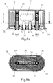
- FIG. 5a, b show a further preferred embodiment.
- the battery 30 is again plugged onto a circuit board 31, which has two square pins 32, 33.
- housing side 36 of the battery 30 opens into the same Way as in the embodiment according to FIG. 12 hollow carrier 34, 35, which on the one hand carry the winding 39 and on the other hand the hollow receptacles for the square pins 32, 33 form.
- the main difference to the embodiment according to FIG. 1 is that in electrochemically unused area between the two hollow supports 34, 35 a flat, sealed electronic circuit 37 is inserted. Their height corresponds approximately a diameter of the hollow carrier 34, 35. It is, for. B. by two contact pins 38, 39 (Pins) contacted, which can be guided through the housing side 36 to the outside. In the circuit board 31 are such. B. in a suitable arrangement between the two Square pins 32, 33 two plug openings 40, 41 are provided, into which the contact pins 38, 39 can be inserted.
- the circuit 37 may e.g. B. an electronic fuse and / or charging electronics his. You can z. B. imagine that on the back of the circuit board 31 a Coil is arranged, which enables inductive coupling to a power transmitter, so that the battery 30 can be charged without contact.
- the charging electronics converted the AC voltage into a DC voltage, which is directly via the hollow beam 34, 35 is delivered to the cathode and anode of the battery.
- a vessel-like injection molded part is manufactured, which is facing inwards projecting pin 9, and on the other hand, a matching cover 5 with round openings (see reference numeral 23).
- a tubular rivet 11 (e.g. made of tinned brass) is inserted into the opening 23. Further a seal 24 is attached on the inside, which defines the transition between tubular rivets 11 and lid 5 sealed.
- the tubes 7, 8 form the carrier for the subsequent winding of the anode, cathode and separator belts 19, 20 and 21, respectively.
- Fig. 4 shows another embodiment. These are the ones that serve as power connections Tubes 25, 26 not only through the lid 27 but also through the bottom 28 passed through. The battery can therefore be contacted from both sides. Be of half of the connecting pins (not shown) inserted into the tubes 25, 26, a similar second battery or a charger can be placed on the connecting pins ("piggyback arrangement").
- the bushing can also be electrically connected to a pole of the battery. On In this way, different holders can be fitted with the same battery type become.
- the internal power connections can also be routed to the outside of the housing that the battery can also be used in conventional holders.
- the tube 25 would e.g. with one attached to the floor Metallization and the tube 26 connected to an attached to the lid 27.
- the construction according to the invention has space can be saved because the contacts between the electronics of the device and the Battery inside the battery and avoid a holder encompassing the battery, and because the plug contact connection also acts as the sole mechanical holder can be used.
- the bracket essentially only needs contact pins to exist, which is a cost saving compared to the known, structurally complex Mounts means.
- the battery With a suitable external shape, the battery can be used for highly miniaturized devices directly attached without additional sheathing ("piggyback") or used as an adapter.
Landscapes
- Chemical & Material Sciences (AREA)
- Chemical Kinetics & Catalysis (AREA)
- Electrochemistry (AREA)
- General Chemical & Material Sciences (AREA)
- Engineering & Computer Science (AREA)
- Manufacturing & Machinery (AREA)
- Battery Mounting, Suspending (AREA)
- Connection Of Batteries Or Terminals (AREA)
Priority Applications (1)
| Application Number | Priority Date | Filing Date | Title |
|---|---|---|---|
| EP99811043.1A EP1100138B1 (fr) | 1999-11-12 | 1999-11-12 | Pile et support de fixation de la pile |
Applications Claiming Priority (1)
| Application Number | Priority Date | Filing Date | Title |
|---|---|---|---|
| EP99811043.1A EP1100138B1 (fr) | 1999-11-12 | 1999-11-12 | Pile et support de fixation de la pile |
Publications (2)
| Publication Number | Publication Date |
|---|---|
| EP1100138A1 true EP1100138A1 (fr) | 2001-05-16 |
| EP1100138B1 EP1100138B1 (fr) | 2017-04-05 |
Family
ID=8243139
Family Applications (1)
| Application Number | Title | Priority Date | Filing Date |
|---|---|---|---|
| EP99811043.1A Expired - Lifetime EP1100138B1 (fr) | 1999-11-12 | 1999-11-12 | Pile et support de fixation de la pile |
Country Status (1)
| Country | Link |
|---|---|
| EP (1) | EP1100138B1 (fr) |
Cited By (4)
| Publication number | Priority date | Publication date | Assignee | Title |
|---|---|---|---|---|
| EP1398841A1 (fr) | 2002-09-16 | 2004-03-17 | Wyon AG | Batterie comprenant une connexion mécaniquement extensible |
| EP2065952A1 (fr) | 2007-11-27 | 2009-06-03 | Swissbatt AG | Batterie |
| WO2010047658A1 (fr) * | 2008-10-23 | 2010-04-29 | Siemens Medical Instruments Pte Ltd | Appareil auditif |
| EP3457453A1 (fr) | 2017-09-13 | 2019-03-20 | Wyon AG | Accumulateur et son procédé de fabrication |
Families Citing this family (1)
| Publication number | Priority date | Publication date | Assignee | Title |
|---|---|---|---|---|
| WO2019091571A1 (fr) | 2017-11-10 | 2019-05-16 | Sonova Ag | Batterie rechargeable avec boîtier non métallique destiné à un dispositif auditif |
Citations (2)
| Publication number | Priority date | Publication date | Assignee | Title |
|---|---|---|---|---|
| EP0531659A1 (fr) * | 1991-07-15 | 1993-03-17 | Saft | Générateur électrochimique de forte énergie massique spécifique |
| JPH10112330A (ja) * | 1996-10-08 | 1998-04-28 | Nissan Motor Co Ltd | 円筒型電池および該円筒型電池を用いた組電池 |
-
1999
- 1999-11-12 EP EP99811043.1A patent/EP1100138B1/fr not_active Expired - Lifetime
Patent Citations (2)
| Publication number | Priority date | Publication date | Assignee | Title |
|---|---|---|---|---|
| EP0531659A1 (fr) * | 1991-07-15 | 1993-03-17 | Saft | Générateur électrochimique de forte énergie massique spécifique |
| JPH10112330A (ja) * | 1996-10-08 | 1998-04-28 | Nissan Motor Co Ltd | 円筒型電池および該円筒型電池を用いた組電池 |
Non-Patent Citations (1)
| Title |
|---|
| PATENT ABSTRACTS OF JAPAN vol. 1998, no. 09 31 July 1998 (1998-07-31) * |
Cited By (7)
| Publication number | Priority date | Publication date | Assignee | Title |
|---|---|---|---|---|
| EP1398841A1 (fr) | 2002-09-16 | 2004-03-17 | Wyon AG | Batterie comprenant une connexion mécaniquement extensible |
| US7294430B2 (en) | 2002-09-16 | 2007-11-13 | Wyon Ag | Battery having a wound electrode element |
| EP2065952A1 (fr) | 2007-11-27 | 2009-06-03 | Swissbatt AG | Batterie |
| US8748024B2 (en) | 2007-11-27 | 2014-06-10 | Swissbatt Ag | Battery |
| WO2010047658A1 (fr) * | 2008-10-23 | 2010-04-29 | Siemens Medical Instruments Pte Ltd | Appareil auditif |
| EP3457453A1 (fr) | 2017-09-13 | 2019-03-20 | Wyon AG | Accumulateur et son procédé de fabrication |
| US10693119B2 (en) | 2017-09-13 | 2020-06-23 | Wyon Ag | Accumulator and method for the manufacture thereof |
Also Published As
| Publication number | Publication date |
|---|---|
| EP1100138B1 (fr) | 2017-04-05 |
Similar Documents
| Publication | Publication Date | Title |
|---|---|---|
| DE3790276C2 (de) | Batteriefach | |
| DE69524894T2 (de) | Prismatische hochleistungsfähige Zelle | |
| DE102013202310B4 (de) | Elektrisches Speicherelement und Verfahren zum Herstellen des elektrischen Speicherelements | |
| DE2705050C3 (de) | Galvanische Zelle | |
| DE112011100279T5 (de) | Batteriezellen- Modul für eine modulare Batterie mit einem verschachtelt angeordnetem Trennelement | |
| EP0380803A2 (fr) | Elément galvanique | |
| DE3511989A1 (de) | Batterieeinheit | |
| DE69432392T2 (de) | Elektrochemische Zelle mit hoher Zuverlässigkeit und Elektrodenanordnung hierfür | |
| DE102005007179A1 (de) | Galvanische Zelle | |
| EP2065952A1 (fr) | Batterie | |
| DE102011109203A1 (de) | Einzelzelle für eine Batterie und eine Batterie | |
| DE10046885B4 (de) | Sekundärbatterie mit einer Vielzahl von durch einen Sammelanschluß verbundenen Elektrodenanschlüssen und Herstellungsverfahren dafür | |
| EP3457453A1 (fr) | Accumulateur et son procédé de fabrication | |
| DE2549377A1 (de) | Implantables reizstromgeraet | |
| DE102013209691A1 (de) | Elektrochemische Zelle und Verfahren zur Herstellung einer elektrochemischen Zelle | |
| EP1100138B1 (fr) | Pile et support de fixation de la pile | |
| DE69818320T2 (de) | Tragbares Gerät, und Batteriegehäuse des tragbaren Gerätes für Gebrauch von verschiedenen Batterietypen konstruiert | |
| EP1398841A1 (fr) | Batterie comprenant une connexion mécaniquement extensible | |
| EP3069397B1 (fr) | Dispositif d'alimentation en énergie | |
| DE10217341A1 (de) | Konischer Schraubenfederkontakt zum Minimieren des Batterie-Gerätekontaktwiderstands, der aus einer isolierenden Schmutzstoffschicht auf demselben stammt | |
| EP3266071A1 (fr) | Connecteur multiple sur rail | |
| DE69116841T2 (de) | Steckvorrichtung für Batterien | |
| EP1336229A1 (fr) | Dispositif de chargement | |
| EP1100139B1 (fr) | Batterie enroulée | |
| DE102022125074B3 (de) | Kontaktelement zum elektrisch leitfähigen kontaktieren eines batteriezellengehäuses |
Legal Events
| Date | Code | Title | Description |
|---|---|---|---|
| PUAI | Public reference made under article 153(3) epc to a published international application that has entered the european phase |
Free format text: ORIGINAL CODE: 0009012 |
|
| AK | Designated contracting states |
Kind code of ref document: A1 Designated state(s): AT BE CH CY DE DK ES FI FR GB GR IE IT LI LU MC NL PT SE |
|
| AX | Request for extension of the european patent |
Free format text: AL;LT;LV;MK;RO;SI |
|
| 17P | Request for examination filed |
Effective date: 20010620 |
|
| AKX | Designation fees paid |
Free format text: AT BE CH CY DE DK ES FI FR GB GR IE IT LI LU MC NL PT SE |
|
| 17Q | First examination report despatched |
Effective date: 20071018 |
|
| GRAP | Despatch of communication of intention to grant a patent |
Free format text: ORIGINAL CODE: EPIDOSNIGR1 |
|
| INTG | Intention to grant announced |
Effective date: 20160713 |
|
| GRAJ | Information related to disapproval of communication of intention to grant by the applicant or resumption of examination proceedings by the epo deleted |
Free format text: ORIGINAL CODE: EPIDOSDIGR1 |
|
| GRAP | Despatch of communication of intention to grant a patent |
Free format text: ORIGINAL CODE: EPIDOSNIGR1 |
|
| INTC | Intention to grant announced (deleted) | ||
| INTG | Intention to grant announced |
Effective date: 20161024 |
|
| GRAS | Grant fee paid |
Free format text: ORIGINAL CODE: EPIDOSNIGR3 |
|
| STAA | Information on the status of an ep patent application or granted ep patent |
Free format text: STATUS: GRANT OF PATENT IS INTENDED |
|
| RAP1 | Party data changed (applicant data changed or rights of an application transferred) |
Owner name: WYON AG |
|
| GRAA | (expected) grant |
Free format text: ORIGINAL CODE: 0009210 |
|
| STAA | Information on the status of an ep patent application or granted ep patent |
Free format text: STATUS: THE PATENT HAS BEEN GRANTED |
|
| AK | Designated contracting states |
Kind code of ref document: B1 Designated state(s): AT BE CH CY DE DK ES FI FR GB GR IE IT LI LU MC NL PT SE |
|
| REG | Reference to a national code |
Ref country code: GB Ref legal event code: FG4D Free format text: NOT ENGLISH |
|
| REG | Reference to a national code |
Ref country code: CH Ref legal event code: EP |
|
| REG | Reference to a national code |
Ref country code: AT Ref legal event code: REF Ref document number: 882581 Country of ref document: AT Kind code of ref document: T Effective date: 20170415 |
|
| REG | Reference to a national code |
Ref country code: CH Ref legal event code: NV Representative=s name: KELLER AND PARTNER PATENTANWAELTE AG, CH |
|
| REG | Reference to a national code |
Ref country code: IE Ref legal event code: FG4D Free format text: LANGUAGE OF EP DOCUMENT: GERMAN |
|
| REG | Reference to a national code |
Ref country code: DE Ref legal event code: R096 Ref document number: 59915461 Country of ref document: DE |
|
| REG | Reference to a national code |
Ref country code: NL Ref legal event code: MP Effective date: 20170405 |
|
| PG25 | Lapsed in a contracting state [announced via postgrant information from national office to epo] |
Ref country code: NL Free format text: LAPSE BECAUSE OF FAILURE TO SUBMIT A TRANSLATION OF THE DESCRIPTION OR TO PAY THE FEE WITHIN THE PRESCRIBED TIME-LIMIT Effective date: 20170405 |
|
| PG25 | Lapsed in a contracting state [announced via postgrant information from national office to epo] |
Ref country code: ES Free format text: LAPSE BECAUSE OF FAILURE TO SUBMIT A TRANSLATION OF THE DESCRIPTION OR TO PAY THE FEE WITHIN THE PRESCRIBED TIME-LIMIT Effective date: 20170405 Ref country code: FI Free format text: LAPSE BECAUSE OF FAILURE TO SUBMIT A TRANSLATION OF THE DESCRIPTION OR TO PAY THE FEE WITHIN THE PRESCRIBED TIME-LIMIT Effective date: 20170405 Ref country code: GR Free format text: LAPSE BECAUSE OF FAILURE TO SUBMIT A TRANSLATION OF THE DESCRIPTION OR TO PAY THE FEE WITHIN THE PRESCRIBED TIME-LIMIT Effective date: 20170706 |
|
| PG25 | Lapsed in a contracting state [announced via postgrant information from national office to epo] |
Ref country code: PT Free format text: LAPSE BECAUSE OF FAILURE TO SUBMIT A TRANSLATION OF THE DESCRIPTION OR TO PAY THE FEE WITHIN THE PRESCRIBED TIME-LIMIT Effective date: 20170807 Ref country code: SE Free format text: LAPSE BECAUSE OF FAILURE TO SUBMIT A TRANSLATION OF THE DESCRIPTION OR TO PAY THE FEE WITHIN THE PRESCRIBED TIME-LIMIT Effective date: 20170405 |
|
| REG | Reference to a national code |
Ref country code: DE Ref legal event code: R097 Ref document number: 59915461 Country of ref document: DE |
|
| PG25 | Lapsed in a contracting state [announced via postgrant information from national office to epo] |
Ref country code: DK Free format text: LAPSE BECAUSE OF FAILURE TO SUBMIT A TRANSLATION OF THE DESCRIPTION OR TO PAY THE FEE WITHIN THE PRESCRIBED TIME-LIMIT Effective date: 20170405 |
|
| PLBE | No opposition filed within time limit |
Free format text: ORIGINAL CODE: 0009261 |
|
| STAA | Information on the status of an ep patent application or granted ep patent |
Free format text: STATUS: NO OPPOSITION FILED WITHIN TIME LIMIT |
|
| PG25 | Lapsed in a contracting state [announced via postgrant information from national office to epo] |
Ref country code: IT Free format text: LAPSE BECAUSE OF FAILURE TO SUBMIT A TRANSLATION OF THE DESCRIPTION OR TO PAY THE FEE WITHIN THE PRESCRIBED TIME-LIMIT Effective date: 20170405 |
|
| 26N | No opposition filed |
Effective date: 20180108 |
|
| PG25 | Lapsed in a contracting state [announced via postgrant information from national office to epo] |
Ref country code: MC Free format text: LAPSE BECAUSE OF FAILURE TO SUBMIT A TRANSLATION OF THE DESCRIPTION OR TO PAY THE FEE WITHIN THE PRESCRIBED TIME-LIMIT Effective date: 20170405 |
|
| GBPC | Gb: european patent ceased through non-payment of renewal fee |
Effective date: 20171112 |
|
| PG25 | Lapsed in a contracting state [announced via postgrant information from national office to epo] |
Ref country code: LU Free format text: LAPSE BECAUSE OF NON-PAYMENT OF DUE FEES Effective date: 20171112 |
|
| REG | Reference to a national code |
Ref country code: FR Ref legal event code: ST Effective date: 20180731 Ref country code: BE Ref legal event code: MM Effective date: 20171130 |
|
| REG | Reference to a national code |
Ref country code: IE Ref legal event code: MM4A |
|
| PG25 | Lapsed in a contracting state [announced via postgrant information from national office to epo] |
Ref country code: IE Free format text: LAPSE BECAUSE OF NON-PAYMENT OF DUE FEES Effective date: 20171112 Ref country code: FR Free format text: LAPSE BECAUSE OF NON-PAYMENT OF DUE FEES Effective date: 20171130 |
|
| PG25 | Lapsed in a contracting state [announced via postgrant information from national office to epo] |
Ref country code: BE Free format text: LAPSE BECAUSE OF NON-PAYMENT OF DUE FEES Effective date: 20171130 Ref country code: GB Free format text: LAPSE BECAUSE OF NON-PAYMENT OF DUE FEES Effective date: 20171112 |
|
| REG | Reference to a national code |
Ref country code: AT Ref legal event code: MM01 Ref document number: 882581 Country of ref document: AT Kind code of ref document: T Effective date: 20171112 |
|
| PG25 | Lapsed in a contracting state [announced via postgrant information from national office to epo] |
Ref country code: AT Free format text: LAPSE BECAUSE OF NON-PAYMENT OF DUE FEES Effective date: 20171112 |
|
| PGFP | Annual fee paid to national office [announced via postgrant information from national office to epo] |
Ref country code: DE Payment date: 20181116 Year of fee payment: 20 |
|
| PGFP | Annual fee paid to national office [announced via postgrant information from national office to epo] |
Ref country code: CH Payment date: 20181011 Year of fee payment: 20 |
|
| PG25 | Lapsed in a contracting state [announced via postgrant information from national office to epo] |
Ref country code: CY Free format text: LAPSE BECAUSE OF NON-PAYMENT OF DUE FEES Effective date: 20170405 |
|
| REG | Reference to a national code |
Ref country code: DE Ref legal event code: R071 Ref document number: 59915461 Country of ref document: DE |
|
| REG | Reference to a national code |
Ref country code: CH Ref legal event code: PL |