EP1099939A2 - Anordnung zur Abgasregelung mit einem Massensensor - Google Patents
Anordnung zur Abgasregelung mit einem Massensensor Download PDFInfo
- Publication number
- EP1099939A2 EP1099939A2 EP00118038A EP00118038A EP1099939A2 EP 1099939 A2 EP1099939 A2 EP 1099939A2 EP 00118038 A EP00118038 A EP 00118038A EP 00118038 A EP00118038 A EP 00118038A EP 1099939 A2 EP1099939 A2 EP 1099939A2
- Authority
- EP
- European Patent Office
- Prior art keywords
- exhaust gas
- sensors
- mass sensor
- arrangement according
- heating
- Prior art date
- Legal status (The legal status is an assumption and is not a legal conclusion. Google has not performed a legal analysis and makes no representation as to the accuracy of the status listed.)
- Withdrawn
Links
Images


Classifications
-
- G—PHYSICS
- G01—MEASURING; TESTING
- G01F—MEASURING VOLUME, VOLUME FLOW, MASS FLOW OR LIQUID LEVEL; METERING BY VOLUME
- G01F1/00—Measuring the volume flow or mass flow of fluid or fluent solid material wherein the fluid passes through a meter in a continuous flow
- G01F1/68—Measuring the volume flow or mass flow of fluid or fluent solid material wherein the fluid passes through a meter in a continuous flow by using thermal effects
- G01F1/684—Structural arrangements; Mounting of elements, e.g. in relation to fluid flow
- G01F1/688—Structural arrangements; Mounting of elements, e.g. in relation to fluid flow using a particular type of heating, cooling or sensing element
- G01F1/69—Structural arrangements; Mounting of elements, e.g. in relation to fluid flow using a particular type of heating, cooling or sensing element of resistive type
- G01F1/692—Thin-film arrangements
-
- F—MECHANICAL ENGINEERING; LIGHTING; HEATING; WEAPONS; BLASTING
- F02—COMBUSTION ENGINES; HOT-GAS OR COMBUSTION-PRODUCT ENGINE PLANTS
- F02M—SUPPLYING COMBUSTION ENGINES IN GENERAL WITH COMBUSTIBLE MIXTURES OR CONSTITUENTS THEREOF
- F02M26/00—Engine-pertinent apparatus for adding exhaust gases to combustion-air, main fuel or fuel-air mixture, e.g. by exhaust gas recirculation [EGR] systems
- F02M26/13—Arrangement or layout of EGR passages, e.g. in relation to specific engine parts or for incorporation of accessories
- F02M26/22—Arrangement or layout of EGR passages, e.g. in relation to specific engine parts or for incorporation of accessories with coolers in the recirculation passage
- F02M26/23—Layout, e.g. schematics
-
- F—MECHANICAL ENGINEERING; LIGHTING; HEATING; WEAPONS; BLASTING
- F02—COMBUSTION ENGINES; HOT-GAS OR COMBUSTION-PRODUCT ENGINE PLANTS
- F02M—SUPPLYING COMBUSTION ENGINES IN GENERAL WITH COMBUSTIBLE MIXTURES OR CONSTITUENTS THEREOF
- F02M26/00—Engine-pertinent apparatus for adding exhaust gases to combustion-air, main fuel or fuel-air mixture, e.g. by exhaust gas recirculation [EGR] systems
- F02M26/45—Sensors specially adapted for EGR systems
- F02M26/46—Sensors specially adapted for EGR systems for determining the characteristics of gases, e.g. composition
- F02M26/47—Sensors specially adapted for EGR systems for determining the characteristics of gases, e.g. composition the characteristics being temperatures, pressures or flow rates
-
- G—PHYSICS
- G01—MEASURING; TESTING
- G01F—MEASURING VOLUME, VOLUME FLOW, MASS FLOW OR LIQUID LEVEL; METERING BY VOLUME
- G01F1/00—Measuring the volume flow or mass flow of fluid or fluent solid material wherein the fluid passes through a meter in a continuous flow
- G01F1/68—Measuring the volume flow or mass flow of fluid or fluent solid material wherein the fluid passes through a meter in a continuous flow by using thermal effects
- G01F1/696—Circuits therefor, e.g. constant-current flow meters
- G01F1/698—Feedback or rebalancing circuits, e.g. self heated constant temperature flowmeters
- G01F1/6983—Feedback or rebalancing circuits, e.g. self heated constant temperature flowmeters adapted for burning-off deposits
-
- F—MECHANICAL ENGINEERING; LIGHTING; HEATING; WEAPONS; BLASTING
- F02—COMBUSTION ENGINES; HOT-GAS OR COMBUSTION-PRODUCT ENGINE PLANTS
- F02M—SUPPLYING COMBUSTION ENGINES IN GENERAL WITH COMBUSTIBLE MIXTURES OR CONSTITUENTS THEREOF
- F02M26/00—Engine-pertinent apparatus for adding exhaust gases to combustion-air, main fuel or fuel-air mixture, e.g. by exhaust gas recirculation [EGR] systems
- F02M26/13—Arrangement or layout of EGR passages, e.g. in relation to specific engine parts or for incorporation of accessories
- F02M26/17—Arrangement or layout of EGR passages, e.g. in relation to specific engine parts or for incorporation of accessories in relation to the intake system
- F02M26/21—Arrangement or layout of EGR passages, e.g. in relation to specific engine parts or for incorporation of accessories in relation to the intake system with EGR valves located at or near the connection to the intake system
-
- F—MECHANICAL ENGINEERING; LIGHTING; HEATING; WEAPONS; BLASTING
- F02—COMBUSTION ENGINES; HOT-GAS OR COMBUSTION-PRODUCT ENGINE PLANTS
- F02M—SUPPLYING COMBUSTION ENGINES IN GENERAL WITH COMBUSTIBLE MIXTURES OR CONSTITUENTS THEREOF
- F02M26/00—Engine-pertinent apparatus for adding exhaust gases to combustion-air, main fuel or fuel-air mixture, e.g. by exhaust gas recirculation [EGR] systems
- F02M26/50—Arrangements or methods for preventing or reducing deposits, corrosion or wear caused by impurities
Definitions
- the invention relates to an arrangement for exhaust gas control according to the preamble of the claim 1.
- a disadvantage of the known arrangements is that an indirect measurement takes place here, whereby the regulation of the exhaust gas recirculation via the intake air, but not via the exhaust gas itself occurs. This leads to inaccurate measurement and control values.
- the object of the invention is to provide an arrangement with which a direct and accurate exhaust gas recirculation measurement for exhaust gas control can take place.
- the invention is based on the idea of an air mass sensor as an exhaust gas mass sensor directly in the exhaust gas recirculation line in front of an exhaust gas recirculation valve (EGR valve) to be able to carry out a direct measurement and control of the exhaust gas.
- EGR valve exhaust gas recirculation valve
- an exhaust gas cooling system is installed in front of the exhaust gas mass sensor and thus cools the exhaust gases.
- the exhaust gas mass sensor is also against heat and Dirt resistant. For this it is necessary that the temperature drift of the sensors of the exhaust gas mass sensor is compensated, and that the sensors are kept so hot that settling dirt is incinerated from the exhaust gases.
- the exhaust gas mass sensor is preferably designed so that it pulsates exhaust gas flows and can measure exhaust gas backflows.
- the exhaust gas mass sensor points to this two separate heating sensors and temperature sensors, which are connected to two Wheatstone bridges.
- the EGR valve and the exhaust gas mass sensor made in one piece.
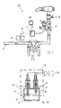
- 1 shows an exhaust gas recirculation system 20 with an arrangement for exhaust gas control.
- 1 is an air filter
- 2 is an air mass sensor
- 3 is an EGR valve with a preference Position feedback
- 4 denotes an intake air throttling, which in known Way interact.
- an exhaust gas recirculation line 6 further air mass sensor 7 as exhaust gas mass sensor.
- the exhaust gas recirculation line 6 has the exhaust gas mass sensor 7 has an exhaust gas cooler 8, for example in the form of a cooling coil.
- This has the task of preferably the exhaust gas recirculation line 6 and the exhaust gas Cool 300 ° C. This means that the following exhaust gas mass sensor 7, in particular whose heating and temperature sensors 9, 10, a temperature range from to exposed to 300 ° C, sometimes up to 500 ° C can occur.
- the exhaust gas mass sensor 7 preferably has two heating sensors 9 and two temperature sensors 10, which is installed in the exhaust gas recirculation line 6 and by a bracket 12 are attached.
- the heating sensors 9 and the temperature sensors 10 are preferably each designed as double ceramic sensors and separated from each other and for example staggered (Fig. 1a).
- the sensors 9, 10 are each on a ceramic carrier 9.1 or 10.1 applied and embedded in a membrane 9.2 or 10.2 (Fig. 3).
- the sensors 9, 10 are each in a known manner to a Wheatstone bridge interconnected, which are located on a component carrier 7.1 of the exhaust gas mass sensor 7, whereby by shifting the internal bridge ratio, the amount of that flowing past Exhaust gas is determined. The direction of the flowing exhaust gas is determined by comparing the two bridge signals. An electrical signal generated in each case is passed to an evaluation unit 13. This controls the EGR valve 3 in such a way that more or less exhaust gases are recycled.
- the EGR valve 3 and the exhaust gas mass sensor 7 are in one piece formed, as shown in Fig. 2. These are also not shown separately Wheatstone bridges and the actual sensor electronics. These can despite high temperatures in the area of the exhaust gas recirculation line 6 in the direct vicinity of the heating sensors 9 and temperature sensors 10 can be integrated on the component carrier 7.1.
- the temperature drift of sensors 9, 10 compensates, which among other things through components with non-linear Properties, e.g. an NTC resistor in the circuit on the component carrier 7.1 can (not shown).
- the sensors 9 are compared up to 300 ° C the exhaust gas temperature heated.
- the temperature sensors 10 can From the back on the ceramic support 10.1 heating resistors are to be provided for free-heating (not shown in detail). The ashed particles are caused by their lightness transported away by the exhaust gas flow from the sensors 9 and 10.
- the sensors 9, 10 are on the foot side with their ceramic supports 9.1, 10.1 in a glass-ceramic casting compound 11 edged so that this connection to the bracket 12 of the exhaust gas mass sensor 7 can take temperatures up to 600 ° C without the ceramic carrier Detach 9.1, 10.1 of sensors 9.10 from bracket 12.
- the measurement results of the air mass sensor 3 in the air intake duct and that of the exhaust gas mass sensor 7 in the exhaust gas recirculation line 6 with one another combined evaluated in the evaluation unit 13, so that a more precise exhaust gas control through the EGR valve 3 also taking into account the fresh air supplied can.
- This arrangement can also be used in direct injection systems with Otto engines become.
- the two heating sensors 9 and the two temperature sensors 10 can also be applied to separate ceramic supports, so that the exhaust gas mass sensor 7 is made up of four individual ceramic supports.
Abstract
Description
eine Anordnung zur Abgasrückführmessung,
eine Darstellung des Abgasmassensensors aus Fig.1,
ein AGR-Ventil mit dem Abgasmassensensor,
eine schematische Darstellung einer Wurzelheizung.
Claims (9)
- Anordnung zur Abgasregelung, aufweisend ein AGR-Ventil, sowie eine Abgasrückführleitung, dadurch gekennzeichnet, daß ein Luftmassensensor (7) als Abgasmassensensor direkt in der Abgasrückführleitung (6) vor dem AGR-Ventil (3) eingebracht ist.
- Anordnung nach Anspruch 1, dadurch gekennzeichnet, daß in der Abgasrückführleitung (6) ein Abgaskühler (8) integriert ist.
- Anordnung nach Anspruch 1 oder 2, dadurch gekennzeichnet, daß das AGR-Ventil (3) und der Abgasmassensensor (7) einteilig ausgeführt sind.
- Anordnung nach einem der Ansprüche 1 bis 3, dadurch gekennzeichnet, daß der Abgasmassensensor (7) zwei Heizsensoren (9) und zwei Temperatursensoren (10) besitzt, die zu zwei Wheatstone-Brücken verschaltet sind.
- Anordnung nach einem der vorgenannten Ansprüche, dadurch gekennzeichnet, daß die Heizsensoren (9) und Temperatursensoren (10) als Doppel-Keramiksensoren ausgeführt sind.
- Anordnung nach einem oder mehreren der vorgenannten Ansprüche, dadurch gekennzeichnet, daß eine Temperaturdrift der Heizsensoren (9) und der Temperatursensoren (10) durch Bauelemente mit nichtlinearen Eigenschaften kompensiert wird.
- Anordnung nach einem oder mehreren der vorgenannten Ansprüche, dadurch gekennzeichnet, daß die Heizsensoren (9) derart beheizt werden, daß sich absetzender Schmutz aus den Rußpartikeln des Abgases verascht wird.
- Anordnung nach einem oder mehreren der vorgenannten Ansprüche, dadurch gekennzeichnet, daß auf dem Keramikträger (10.1) der Temperatursensoren (10) von hinten Heizwiderstände zum Freiglühen angebracht sind.
- Anordnung nach einem der vorgenannten Ansprüche, dadurch gekennzeichnet, daß die Heizsensoren (9) und die Temperatursensoren (10) sind fußseitig mit ihren Keramikträgern (9.1, 10.1) in einer Glas-Keramik-Vergußmasse (11) eingefaßt sind.
Applications Claiming Priority (2)
| Application Number | Priority Date | Filing Date | Title |
|---|---|---|---|
| DE19953718A DE19953718A1 (de) | 1999-11-09 | 1999-11-09 | Anordnung zur Abgasregelung |
| DE19953718 | 1999-11-09 |
Publications (2)
| Publication Number | Publication Date |
|---|---|
| EP1099939A2 true EP1099939A2 (de) | 2001-05-16 |
| EP1099939A3 EP1099939A3 (de) | 2002-09-18 |
Family
ID=7928320
Family Applications (1)
| Application Number | Title | Priority Date | Filing Date |
|---|---|---|---|
| EP00118038A Withdrawn EP1099939A3 (de) | 1999-11-09 | 2000-08-23 | Anordnung zur Abgasregelung mit einem Massensensor |
Country Status (2)
| Country | Link |
|---|---|
| EP (1) | EP1099939A3 (de) |
| DE (1) | DE19953718A1 (de) |
Cited By (11)
| Publication number | Priority date | Publication date | Assignee | Title |
|---|---|---|---|---|
| WO2003031354A1 (de) * | 2001-10-02 | 2003-04-17 | Ballard Power Systems Ag | Brennstoffzellensystem mit einem massenstromsensor |
| WO2003095947A1 (en) * | 2002-05-10 | 2003-11-20 | Melexis Nv | Hot wire mass flow measurement device for a high temperature gas |
| DE102005051182A1 (de) * | 2005-10-24 | 2007-04-26 | Heraeus Sensor Technology Gmbh | Störmungssensorelement und dessen Selbstreinigung |
| DE102005061533A1 (de) * | 2005-12-22 | 2007-07-05 | Pierburg Gmbh | Abgasmassenstromsensor sowie Verfahren zum Betreiben eines Abgasmassenstromsensors |
| DE102006030786A1 (de) * | 2006-06-30 | 2008-01-03 | Heraeus Sensor Technology Gmbh | Strömungssensorelement und dessen Selbstreinigung |
| US7739908B2 (en) | 2005-10-24 | 2010-06-22 | Heraeus Sensor Technology Gmbh | Flow sensor element and its self-cleaning |
| US8050847B2 (en) | 2005-12-22 | 2011-11-01 | Pierburg Gmbh | Method for operating an exhaust gas mass flow sensor |
| WO2013034393A1 (de) * | 2011-09-09 | 2013-03-14 | Pierburg Gmbh | Verfahren zur steuerung eines abgassystems eines dieselmotors sowie abgassystem eines dieselmotors |
| WO2013087245A1 (de) * | 2011-12-16 | 2013-06-20 | Pierburg Gmbh | Verfahren zur steuerung eines abgassystems eines dieselmotors |
| JP2013532831A (ja) * | 2010-08-03 | 2013-08-19 | ピールブルク ゲゼルシャフト ミット ベシュレンクテル ハフツング | 排気ガス流量センサでの合成全流量を求める方法 |
| WO2017064236A1 (fr) | 2015-10-16 | 2017-04-20 | Mmt Sa | Vanne motorisee instrumentee |
Families Citing this family (5)
| Publication number | Priority date | Publication date | Assignee | Title |
|---|---|---|---|---|
| DE10233822A1 (de) * | 2002-07-25 | 2004-02-26 | Daimlerchrysler Ag | Verfahren und Anordnung zur Bestimmung der von einem Verdichter in einem Brennstoffzellensystem angesaugten Gasmasse |
| DE102006053646B4 (de) * | 2006-11-14 | 2008-09-18 | Continental Automotive Gmbh | Strömungssensor |
| EP2251651A3 (de) | 2007-04-26 | 2012-02-22 | Heraeus Sensor Technology Gmbh | Anordnung eines Schichtwiderstandes einer anemometrischen Messeinrichtung in einem Abgasrohr |
| CN102177431B (zh) * | 2008-10-09 | 2013-07-03 | 丰田自动车株式会社 | 排气传感器的活性判定装置、内燃机的控制装置 |
| DE102011009754A1 (de) | 2011-01-28 | 2012-08-02 | Heraeus Sensor Technology Gmbh | Strömungssensoren mit Stromdurchführung im Deckel und Sensorspitze als Zwischenprodukt |
Citations (3)
| Publication number | Priority date | Publication date | Assignee | Title |
|---|---|---|---|---|
| DE3932304A1 (de) * | 1989-09-28 | 1991-04-11 | Bosch Gmbh Robert | Verfahren und vorrichtung zur temperatursteuerung eines messwiderstands |
| US5601068A (en) * | 1995-07-05 | 1997-02-11 | Nozel Engineering Co., Ltd. | Method and apparatus for controlling a diesel engine |
| DE19801484A1 (de) * | 1997-01-16 | 1998-07-23 | Hitachi Ltd | Meßelement und damit ausgerüsteter Luftmassenmesser |
Family Cites Families (2)
| Publication number | Priority date | Publication date | Assignee | Title |
|---|---|---|---|---|
| JPH05340311A (ja) * | 1992-06-08 | 1993-12-21 | Unisia Jecs Corp | 排気ガス還流装置の故障診断装置 |
| JPH10141146A (ja) * | 1996-11-11 | 1998-05-26 | Nissan Motor Co Ltd | エンジンのegr制御装置 |
-
1999
- 1999-11-09 DE DE19953718A patent/DE19953718A1/de not_active Withdrawn
-
2000
- 2000-08-23 EP EP00118038A patent/EP1099939A3/de not_active Withdrawn
Patent Citations (3)
| Publication number | Priority date | Publication date | Assignee | Title |
|---|---|---|---|---|
| DE3932304A1 (de) * | 1989-09-28 | 1991-04-11 | Bosch Gmbh Robert | Verfahren und vorrichtung zur temperatursteuerung eines messwiderstands |
| US5601068A (en) * | 1995-07-05 | 1997-02-11 | Nozel Engineering Co., Ltd. | Method and apparatus for controlling a diesel engine |
| DE19801484A1 (de) * | 1997-01-16 | 1998-07-23 | Hitachi Ltd | Meßelement und damit ausgerüsteter Luftmassenmesser |
Non-Patent Citations (2)
| Title |
|---|
| PATENT ABSTRACTS OF JAPAN vol. 018, no. 183 (M-1584), 29. März 1994 (1994-03-29) & JP 05 340311 A (JAPAN ELECTRON CONTROL SYST CO LTD), 21. Dezember 1993 (1993-12-21) * |
| PATENT ABSTRACTS OF JAPAN vol. 1998, no. 10, 31. August 1998 (1998-08-31) & JP 10 141146 A (NISSAN MOTOR CO LTD), 26. Mai 1998 (1998-05-26) * |
Cited By (13)
| Publication number | Priority date | Publication date | Assignee | Title |
|---|---|---|---|---|
| WO2003031354A1 (de) * | 2001-10-02 | 2003-04-17 | Ballard Power Systems Ag | Brennstoffzellensystem mit einem massenstromsensor |
| WO2003095947A1 (en) * | 2002-05-10 | 2003-11-20 | Melexis Nv | Hot wire mass flow measurement device for a high temperature gas |
| US7739908B2 (en) | 2005-10-24 | 2010-06-22 | Heraeus Sensor Technology Gmbh | Flow sensor element and its self-cleaning |
| DE102005051182A1 (de) * | 2005-10-24 | 2007-04-26 | Heraeus Sensor Technology Gmbh | Störmungssensorelement und dessen Selbstreinigung |
| DE102005061533A1 (de) * | 2005-12-22 | 2007-07-05 | Pierburg Gmbh | Abgasmassenstromsensor sowie Verfahren zum Betreiben eines Abgasmassenstromsensors |
| DE102005061533B4 (de) * | 2005-12-22 | 2007-12-06 | Pierburg Gmbh | Abgasmassenstromsensor sowie Verfahren zum Betreiben eines Abgasmassenstromsensors |
| US8050847B2 (en) | 2005-12-22 | 2011-11-01 | Pierburg Gmbh | Method for operating an exhaust gas mass flow sensor |
| DE102006030786A1 (de) * | 2006-06-30 | 2008-01-03 | Heraeus Sensor Technology Gmbh | Strömungssensorelement und dessen Selbstreinigung |
| JP2013532831A (ja) * | 2010-08-03 | 2013-08-19 | ピールブルク ゲゼルシャフト ミット ベシュレンクテル ハフツング | 排気ガス流量センサでの合成全流量を求める方法 |
| WO2013034393A1 (de) * | 2011-09-09 | 2013-03-14 | Pierburg Gmbh | Verfahren zur steuerung eines abgassystems eines dieselmotors sowie abgassystem eines dieselmotors |
| WO2013087245A1 (de) * | 2011-12-16 | 2013-06-20 | Pierburg Gmbh | Verfahren zur steuerung eines abgassystems eines dieselmotors |
| WO2017064236A1 (fr) | 2015-10-16 | 2017-04-20 | Mmt Sa | Vanne motorisee instrumentee |
| FR3042575A1 (fr) * | 2015-10-16 | 2017-04-21 | Mmt Sa | Vanne motorisee instrumentee |
Also Published As
| Publication number | Publication date |
|---|---|
| DE19953718A1 (de) | 2001-05-10 |
| EP1099939A3 (de) | 2002-09-18 |
Similar Documents
| Publication | Publication Date | Title |
|---|---|---|
| EP1099939A2 (de) | Anordnung zur Abgasregelung mit einem Massensensor | |
| WO2008000494A2 (de) | Schichtwiderstand im abgasrohr | |
| EP0269781A1 (de) | Vorrichtung zur Bestimmung des Massenstromes und der Durchflussrichtung | |
| DE102012108350B3 (de) | Vorrichtung und Verfahren zur Rekalibrierung eines Abgasmassenstromsensors | |
| DE4112601C2 (de) | Vorrichtung zur Messung eines Gasstroms | |
| WO2008131890A2 (de) | Schichtwiderstand im abgasrohr | |
| DE102013218271A1 (de) | Thermisches Luftflussmeter | |
| DE102006058425A1 (de) | Abgasrückführung mit einem Anemometer | |
| DE19506605A1 (de) | Luftflußmengenerfassungsanordnung vom Heißfilmtyp verwendbar bei einem Fahrzeugmotor mit innerer Verbrennung | |
| DE102009018525B4 (de) | Abgasrückführsystem für einen Verbrennungsmotor | |
| DE102005038597A1 (de) | Heissfilmluftmassenmesser mit frequenzmodulierter Signalerfassung | |
| DE102012102094A1 (de) | Vorrichtung zur Bestimmung eines Gasmassenstroms sowie Verfahren zur Rekalibrierung einer derartigen Vorrichtung | |
| DE19819855A1 (de) | Luftmassensensor | |
| EP2035785A1 (de) | Messvorrichtung zur messung der durchflussrate eines verbrennungsgas-gemisches, aufweisend eine korrektureinrichtung | |
| DE102004033049B4 (de) | Messeinrichtung für einen Durchflusssensor, insbesondere einen Luftmassensensor für Brennkraftmaschinen und Verfahren zum Messen von Luftströmen | |
| EP1356198A1 (de) | Verfahren und vorrichtung zur ermittlung des durchsatzes eines strömenden mediums | |
| DE102005041537B4 (de) | Verfahren zur Überwachung eines Rußpartikelfilters | |
| EP0720726B1 (de) | Verfahren und schaltungsanordnung zum schutz eines beheizten temperaturabhängigen sensorwiderstands vor überhitzung | |
| DE102005006152B4 (de) | Detektoreinrichtung zur Ermittlung einer Filterverstopfung | |
| EP0163846A1 (de) | Vorrichtung zur Messung der Masse eines strömenden Mediums | |
| WO2005111401A1 (de) | Verfahren und vorrichtung zur bestimmung einer abgasrückführungsrate | |
| DE102009018526B4 (de) | Abgasrückführsystem für einen Verbrennungsmotor | |
| DE102006038596A1 (de) | Messvorrichtung zur Erfassung eines Gasmassenstroms | |
| EP0589211A2 (de) | Steuer- und Auswerteschaltung für einen Luftmassenstromsensor | |
| EP0751378B1 (de) | Vorrichtung zur Bestimmung des Luftmassenstromes |
Legal Events
| Date | Code | Title | Description |
|---|---|---|---|
| PUAI | Public reference made under article 153(3) epc to a published international application that has entered the european phase |
Free format text: ORIGINAL CODE: 0009012 |
|
| 17P | Request for examination filed |
Effective date: 20000823 |
|
| AK | Designated contracting states |
Kind code of ref document: A2 Designated state(s): AT BE CH CY DE DK ES FI FR GB GR IE IT LI LU MC NL PT SE |
|
| AX | Request for extension of the european patent |
Free format text: AL;LT;LV;MK;RO;SI |
|
| RAP1 | Party data changed (applicant data changed or rights of an application transferred) |
Owner name: PIERBURG GMBH |
|
| PUAL | Search report despatched |
Free format text: ORIGINAL CODE: 0009013 |
|
| AK | Designated contracting states |
Kind code of ref document: A3 Designated state(s): AT BE CH CY DE DK ES FI FR GB GR IE IT LI LU MC NL PT SE |
|
| AX | Request for extension of the european patent |
Free format text: AL;LT;LV;MK;RO;SI |
|
| RIC1 | Information provided on ipc code assigned before grant |
Free format text: 7G 01F 1/698 A, 7F 02M 25/07 B |
|
| AKX | Designation fees paid |
Designated state(s): DE FR GB IT |
|
| STAA | Information on the status of an ep patent application or granted ep patent |
Free format text: STATUS: THE APPLICATION HAS BEEN WITHDRAWN |
|
| 18W | Application withdrawn |
Effective date: 20050317 |