EP1099876B1 - Damping support for an object - Google Patents
Damping support for an object Download PDFInfo
- Publication number
- EP1099876B1 EP1099876B1 EP99710014A EP99710014A EP1099876B1 EP 1099876 B1 EP1099876 B1 EP 1099876B1 EP 99710014 A EP99710014 A EP 99710014A EP 99710014 A EP99710014 A EP 99710014A EP 1099876 B1 EP1099876 B1 EP 1099876B1
- Authority
- EP
- European Patent Office
- Prior art keywords
- base
- support
- ring
- damping
- shock absorber
- Prior art date
- Legal status (The legal status is an assumption and is not a legal conclusion. Google has not performed a legal analysis and makes no representation as to the accuracy of the status listed.)
- Expired - Lifetime
Links
Images

Classifications
-
- F—MECHANICAL ENGINEERING; LIGHTING; HEATING; WEAPONS; BLASTING
- F16—ENGINEERING ELEMENTS AND UNITS; GENERAL MEASURES FOR PRODUCING AND MAINTAINING EFFECTIVE FUNCTIONING OF MACHINES OR INSTALLATIONS; THERMAL INSULATION IN GENERAL
- F16F—SPRINGS; SHOCK-ABSORBERS; MEANS FOR DAMPING VIBRATION
- F16F7/00—Vibration-dampers; Shock-absorbers
- F16F7/14—Vibration-dampers; Shock-absorbers of cable support type, i.e. frictionally-engaged loop-forming cables
Definitions
- the invention relates to a device for damped storage of an object in an environment that is prone to vibration and / or impact with one in this environment mounted base and a connected to it via a damping element Carrier for the object.
- damping element u. a. every system with one Understanding combination of elastic and cushioning properties independently whether it's interacting in a single component or in multiple Components. That is, such a damping element has in usually a restoring force that the damping element in a Forcing the rest position back, and on the other hand a damping characteristic for prevention of natural vibrations.
- vibration and shock-sensitive devices especially electronic or precision mechanical Devices, such as computers, monitors or printers in Water, air or land vehicles, especially all-terrain land vehicles.
- DE 44 19 890 C2 is a screen workstation for mobile remote control and control cabins using vibration and shock absorption for the used equipment known. This is done, for example, on the floor of the cabin fixed frame, a worktop can be inserted into guides attached vibration and shock absorber, that is, the table top is over here appropriate damping elements connected to the frame as a base.
- GB-A-2 224 068 discloses the preamble of claim 1.
- shock absorbers Due to the parallel bumper, at a force that could cause the Tear damping element, much of this force is absorbed in the bumper and dampened the movement. These shock absorbers therefore have the function a soft stop, which on the one hand ensures that the maximum Damping element destructive deflection is not exceeded, on the other but also, unlike a hard hit, it ensures that the impact energy not transferred to the carrier and passed on to the object undamped becomes.
- the bumper has an elongated tension element, which consists of elastic material and which on the one hand at the base and on the other hand is fixed to the carrier.
- an elastic tension element can reset properties at the same time in a relatively simple manner and the cushioning properties are realized.
- the invention provides an O-ring as a tension element, such an O-ring on at least one ring section at the base and on at least one Ring section is fixed to the carrier.
- a tension element such an O-ring on at least one ring section at the base and on at least one Ring section is fixed to the carrier.
- Such an O-ring for example made of rubber or Viton, has excellent elastic properties in such a way that it becomes less than a certain load Tapering its material cross section elastically elongates and thus for the one mentioned here
- Use as a bumper has a pronounced non-linear characteristic.
- O-rings in various commercially available sizes, that is with the most diverse opening cross-sections and material cross-sections, procurable. The tension elements therefore do not have to be made to order become.
- the o-ring is preferably on diametrically opposite sides of the O-ring fixed to the base and carrier, with the O-ring in the rest position between the base and the carrier with regard to its opening cross section can be arranged deformed.
- a bumper is used, the restoring force of which is non-linear means disproportionately or even strongly disproportionately increases, e.g. B. can Spring constant due to a change in the type of deformation in the course of the deflection solid rising.
- each of these bumpers are parallel arranged to the damping element so that each above the threshold increasing geometric deflection between the base and the beam independently is limited in direction by at least one of the bumpers.
- each above the threshold increasing geometric deflection between the base and the beam independently is limited in direction by at least one of the bumpers.
- the O-ring is different on the base and on the carrier long ring sections firmly clamped between the base and the carrier arranged deformed with respect to its opening cross-section that in the rest position the free ring sections between the base and the carrier run diagonally away from each other. So one O-ring already makes two linearly independent spatial directions recorded.
- Clamping the O-ring on the base and on the carrier can also counteract the shape of the O-ring.
- the O-ring is clamped in an elongated block.
- the base is essentially from a base plate and the carrier from a carrier plate, which essentially parallel to each other at a relatively short distance from each other are arranged. That is, the entire device is as a flat modular Assembly platform set up.
- the carrier is essentially a trough shape has, whose base extends as a carrier plate parallel to the base plate and whose peripheral side walls extend in the direction of the base plate.
- the carrier simultaneously forms a kind of lid-shaped housing for the entire Device so that the damping elements and the bumpers in front of one Intervention from outside are protected. Above all, such a circumferential prevents case-shaped edge also that objects between the support plate and the Base plate reach and can override the damping effect.
- the base it is also possible for the base to be constructed in the form of a tub is in which the carrier plate is inserted.
- the trough-shaped carrier has a recess as an assembly opening.
- the respective object can also by one or more further damping elements can be coupled to the carrier in order to the residual vibrations that still reach the carrier via the device to dampen.
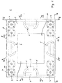
- the device according to the invention shown in the figures has a quadrangular one Base plate 2 on, at all four corner points hydrodynamic damping elements 4 are mounted.
- hydrodynamic high-performance vibration dampers 4 are concerned are spring-elastomer dampers with particularly high internal damping. At a Special embodiment, these are dampers from the company Stop-choc, for example of the type E1FH781-S01 or E1 FH781-C01. This Damper 4 are attached at their base on base pieces 9 on the base plate 2.
- the dampers 4 On the opposite, upper side, the dampers 4 have a flange 10 with which it is attached to the base 11 of a trough-shaped support 3 are, the circumferential side walls 12 down towards the Extend base plate 2.
- the base plate 2 thus forms together with the trough-shaped support 3 and the damping elements mounted in between 4 a module-like assembly platform, the base 2 generally being stationary in the vibration and / or shock-prone environment is installed and the Carrier 3 serves as a platform for the object to be stored damped.
- the distance between the upper edge of the base plate 2 and the inside of the base 11 of the trough-shaped carrier 3 approx. 56 mm.
- the basic dimensions of the trough-shaped support 3 are approx. 430 mm x 370 mm.
- the hydrodynamic dampers 4 show in its upper cylindrical region below the flange 10 has a diameter from 43 mm.
- the four side edges are in the middle, parallel to those at the corners of the base plate 2 arranged damping elements 4 acting bumpers 5 arranged.
- These bumpers each consist of an O-ring 6, which is in elongated, parallel clamping blocks 7, 8 on the one hand on the base plate 2 and on the other is firmly clamped to the base 11 of the trough-shaped support 3.
- the O-ring in the mounting blocks 7, 8 is each on a ring section 13, 14 just clamped against its own shape.
- the mounting blocks 7 on the base plate 2 are opposite the mounting blocks 8 arranged on the carrier 3 each offset inwards. This leads to the free Ring sections 15, 16 of the O-ring 6 each run obliquely outwards.
- the length b of the mounting block 7 located on the base plate 2 less than the length a of the base 11 of the carrier 3 Assembly blocks 8.
- the length b of the mounting block 7 at the base 40 mm the length a of the mounting block 8 on the support 80 mm. Because of these different clamping lengths a, b, the free ring sections 15, 16 run between the base and the carrier obliquely away from each other along the direction R1, R2.
- the four O-rings 6 therefore have the effect of 8 different ones Tension elements, each in different directions R1 to R8 along the The circumference of the base plate 2 or the carrier 3 extend outwards, so that each geometric deflection between the base 2 and the carrier 3 independently is limited in its direction by at least one of the bumpers 5.
- the O-rings 6 consequently form a very soft stop, which ensures that the deflection except for one for the damping elements 4 permissible maximum value is limited.
- the bumper 5 can also absorb the greatest momentary loads, such as those encountered in a uncontrolled superposition of different vibrations and shocks occur without the damping elements 4 being destroyed. All in all the device 1 according to the invention is therefore capable of vibrations and bumps in an extraordinarily wide frequency range and at very high ones Process loads.
- the device 1 also has the advantage that it is flexible for storing various Objects can be used. An adjustment to the respective weight of the object is due to the number of damping elements 4 and the preload of the O-rings 6 or, if necessary, by simply exchanging the O-rings for O-rings with other geometrical dimensions possible.
- O-rings 6 with a Opening cross section of approx. 70 mm and a material cross section of approx. 12 mm used.
- Stop-choc is the device capable of objects weighing between 15 and safely store 22 kg shock and vibration damped.
- To weights between To store 20 and 30 kg are on the base 11 of the trough-shaped Beam 3, right next to the damping elements 4, additional optional Damping elements 18 of the same type are arranged.
- the bias on the O-rings 6 is increased by z. B. longer Clamping blocks 7, 8 are used and thus the free sections 15, 16 of the O-rings 6 can be shortened.
- the device according to the invention was operated under the conditions in unsprung tracked vehicles with the standard MIL 810E-514.4-1, cath. 8, ed. I-3.4.7, crew compartement walls, Tab A XIX, tested and scored excellent here Results achieved.
- Vibration frequencies between 200 and 1000 Hz with vibrations between 50 and 200 Hz and shocks between 20 and 50 Hz superimposed.
- the bumps have a load of up to 40 g, the vibration up to 18 g.
- On the carrier 3 was also on additional damping elements of the same type as used between the beam and the base commercial inkjet printer mounted. This inkjet printer was during of the entire test fully operational. The generated during the test run Printouts were of the same quality as before and after the test generated printouts.
Abstract
Description
Die Erfindung betrifft eine Vorrichtung zur gedämpften Lagerung eines Objekts in einer schwingungs- und/oder stoßgefährdeten Umgebung mit einer in dieser Umgebung montierten Basis und einem damit über ein Dämpfungselement verbundenen Träger für das Objekt.The invention relates to a device for damped storage of an object in an environment that is prone to vibration and / or impact with one in this environment mounted base and a connected to it via a damping element Carrier for the object.
Unter dem Begriff Dämpfungselement ist hierbei u. a. jedes System mit einer Kombination von elastischen und dämpfenden Eigenschaften zu verstehen, unabhängig davon, ob es in einem einzelnen Bauteil oder in mehreren zusammenwirkenden Bauteilen besteht. Das heißt, ein solches Dämpfungselement weist in der Regel zum einen eine Rückstellkraft, welche das Dämpfungselement in eine Ruhelage zurück zwingt, und zum anderen eine Dämpfcharakteristik zur Verhinderung von Eigenschwingungen auf.Under the term damping element u. a. every system with one Understanding combination of elastic and cushioning properties independently whether it's interacting in a single component or in multiple Components. That is, such a damping element has in usually a restoring force that the damping element in a Forcing the rest position back, and on the other hand a damping characteristic for prevention of natural vibrations.
Ein wichtiges Einsatzgebiet derartiger Vorrichtungen ist die Lagerung von schwingungs- und stoßempfindlichen Geräten, insbesondere elektronischen oder feinmechanischen Geräten, beispielsweise Computer, Bildschirme oder Drucker in Wasser-, Luft- oder Landfahrzeugen, insbesondere geländegängigen Landfahrzeugen.An important area of application of such devices is the storage of vibration and shock-sensitive devices, especially electronic or precision mechanical Devices, such as computers, monitors or printers in Water, air or land vehicles, especially all-terrain land vehicles.
Unter extremen Bedingungen sind solche Fahrzeuge einem sehr breitbandigen Spektrum an Schwingungen und Stößen ausgesetzt. So können beispielsweise Stöße bis 40 g (g : Erdbeschleunigung) in einem Frequenzbereich von 20 bis 50 Hz auftreten. Darüber hinaus gibt es Schwingungen mit einer Belastung von bis zu 18 g im Bereich von 50 bis 200 Hz. Insbesondere bei kettengetriebenen Landfahrzeugen kommt ein typisches Kettenrauschen mit einer Frequenz von 200 bis 1000 Hz hinzu, welches die übrigen Schwingungen und Stöße überlagert. Sowohl die durch die Ketten bedingten Schwingungen als auch die übrigen Schwingungen und Stöße können in jede beliebige Raumrichtung erfolgen und sind nicht korreliert. Dies führt zwangsläufig dazu, daß zufällig Ablenkungsamplituden mit gleicher Richtung zusammentreffen, was in einer völlig unkontrollierten starken momentanen Amplitudenüberhöhung resultiert. Hierbei treten enorme Beschleunigungskräfte auf.Under extreme conditions, such vehicles are very broadband Exposed to vibrations and shocks. For example Shocks up to 40 g (g: gravitational acceleration) in a frequency range from 20 to 50 Hz occur. In addition, there are vibrations with a load of up to 18 g in the range from 50 to 200 Hz. Especially for chain-driven land vehicles there is a typical chain noise with a frequency of 200 to 1000 Hz added, which superimposes the other vibrations and shocks. Both the vibrations caused by the chains as well as the other vibrations and impacts can occur in any spatial direction and are not correlated. This inevitably leads to random deflection amplitudes having the same Direction meet what is in a completely uncontrolled strong momentary Increased amplitude results. Here enormous acceleration forces occur on.
Aus der DE 44 19 890 C2 ist ein Bildschirmarbeitsplatz für mobile Fern- und Führungskabinen unter Verwendung einer Schwingungs- und Stoßdämpfung für die eingesetzten Arbeitsgeräte bekannt. Hierbei wird beispielsweise auf einem am Kabinenboden befestigten Gestell eine Arbeitsplatte in Führungen einschiebbar schwingungs- und stoßgedämpft befestigt, das heißt, die Tischplatte ist hier über entsprechende Dämpfungselemente mit dem Gestell als Basis verbunden.DE 44 19 890 C2 is a screen workstation for mobile remote control and control cabins using vibration and shock absorption for the used equipment known. This is done, for example, on the floor of the cabin fixed frame, a worktop can be inserted into guides attached vibration and shock absorber, that is, the table top is over here appropriate damping elements connected to the frame as a base.
Zur schwingungsgedämpften Lagerung gibt es inzwischen fertig konfektionierte Dämpfer. Als Hochleistungsdämpfer bieten sich beispielsweise bestimmte hydrodynamische Dämpfer an. Hierbei handelt es sich um Feder-Elastomer-Dämpfer mit hoher Eigendämpfung, die vollständig in einem Gehäuse eingeschlossen sind und einerseits an der Basis und andererseits an dem Träger befestigt werden. Die rückstellenden Eigenschaften erhalten sie durch nichtlineare Tellerfedern. Die Dämpfung erfolgt aufgrund von Silikonfett, das durch Membranen gepreßt wird. Diese Dämpfungselemente sind in der Lage, die "normalerweise" auftretenden Schwingungen in den genannten Frequenzbereichen relativ gut zu verkraften. Problematisch ist jedoch die hohe Belastung bei einer momentanen Amplitudenaddition. Solche schockartigen Amplitudenüberhöhungen führen im Extremfall zu einer Zerstörung, beispielsweise zu einem Abriß der Dämpfungselemente. Insbesondere ist bei den bekannten Dämpfungselementen die Scherbelastbarkeit relativ gering.Ready-made bearings are now available for vibration-damped storage Damper. Certain hydrodynamic dampers, for example, are suitable as high-performance dampers Damper on. These are spring-elastomer dampers with high internal damping, which are completely enclosed in a housing and on the one hand to the base and on the other hand to the carrier. The they have restoring properties through non-linear disc springs. The Damping is due to silicone grease that is pressed through membranes. These damping elements are able to "normally" occur Able to cope with vibrations in the mentioned frequency ranges relatively well. Problematic is the high load with a momentary amplitude addition. Such shock-like amplitude increases lead in extreme cases to destruction, for example to a demolition of the damping elements. In particular the shear strength is relative in the known damping elements low.
Eine ideale Lagerung, um solche schockartigen Amplitudenüberhöhungen zu überstehen, würde beispielsweise darin bestehen, das Objekt so gedämpft aufzuhängen, daß es relativ weit auslenken kann, um auf der langen Wegstrecke die Stoßenergie weitgehend zu absorbieren. Andererseits ist aber gerade bei dem gewünschten Einsatzzweck in Fahrzeugen der Platz in der Regel begrenzt, so daß nur geringe Auslenkungsamplituden zugelassen sind.An ideal position for such shock-like increases in amplitude survive, would consist, for example, of hanging the object so damped that it can deflect relatively far to the long distance Largely absorb impact energy. On the other hand, it is precisely what you want Purpose in vehicles the space is usually limited so that only small deflection amplitudes are permitted.
Aus der GB-A-2 224 068 ist der Oberbegriff des Anspruchs 1 bekannt. GB-A-2 224 068 discloses the preamble of
Es ist daher Aufgabe der vorliegenden Erfindung, eine Vorrichtung anzugeben, die in der Lage ist, ein Objekt in einer derart extremen schwingungs- und/oder stoßgefährdeten Umgebung sicher gedämpft zu lagern und insbesondere auch größere momentane Kräfte sicher absorbiert, ohne dass die Vorrichtung oder das Objekt beschädigt bzw. zerstört werden.It is therefore an object of the present invention to provide a device which is able to object in such an extreme vibration and / or shock hazard Store the environment in a cushioned manner, especially larger ones instantaneous forces safely absorbed without the device or object be damaged or destroyed.
Diese Aufgabe wird durch die Merkmale des Anspruchs 1 gelöst.This object is solved by the features of
Durch den parallelen Stoßfänger wird bei einer Kraft, die dazu führen könnte, das Dämpfungselement zu zerreißen, ein Großteil dieser Kraft im Stoßfänger absorbiert und die Bewegung gedämpft. Diese Stoßdämpfer haben folglich die Funktion eines weichen Anschlags, der zum einen dafür sorgt, dass die maximale das Dämpfungselement zerstörende Auslenkung nicht überschritten wird, zum anderen aber auch, im Gegensatz zu einem harten Anschlag, dafür sorgt, dass die Stoßenergie nicht auf den Träger übertragen und so an das Objekt ungedämpft weitergeleitet wird.Due to the parallel bumper, at a force that could cause the Tear damping element, much of this force is absorbed in the bumper and dampened the movement. These shock absorbers therefore have the function a soft stop, which on the one hand ensures that the maximum Damping element destructive deflection is not exceeded, on the other but also, unlike a hard hit, it ensures that the impact energy not transferred to the carrier and passed on to the object undamped becomes.
Bei der Erfindung weist der Stoßfänger ein langgestrecktes Zugelement auf, welches aus elastischem Material besteht und welches zum einen an der Basis und zum anderen am Träger fixiert ist. Mit einem solchen elastischen Zugelement können gleichzeitig auf relativ einfache Weise die rückstellenden Eigenschaften und die dämpfenden Eigenschaften verwirklicht werden.In the invention, the bumper has an elongated tension element, which consists of elastic material and which on the one hand at the base and on the other hand is fixed to the carrier. With such an elastic tension element can reset properties at the same time in a relatively simple manner and the cushioning properties are realized.
Als Zugelement sieht die Erfindung dabei einen O-Ring vor, wobei ein solcher O-Ring auf zumindest einem Ringabschnitt an der Basis und auf zumindest einem Ringabschnitt am Träger fixiert ist. Ein solcher O-Ring, beispielsweise aus Gummi oder Viton, hat hervorragende elastische Eigenschaften derart, daß er sich ab einer bestimmten Belastung unter Verjüngung seines Materialquerschnittes elastisch langzieht und somit für den hier genannten Einsatz als Stoßfänger eine ausgeprägt nichtlineare Kennlinie aufweist. Außerdem sind derartige O-Ringe in verschiedensten handelsüblichen Größen, das heißt mit den unterschiedlichsten Öffnungsquerschnitten und Materialquerschnitten, beschaffbar. Die Zugelemente müssen folglich nicht als Spezialanfertigung hergestellt werden. The invention provides an O-ring as a tension element, such an O-ring on at least one ring section at the base and on at least one Ring section is fixed to the carrier. Such an O-ring, for example made of rubber or Viton, has excellent elastic properties in such a way that it becomes less than a certain load Tapering its material cross section elastically elongates and thus for the one mentioned here Use as a bumper has a pronounced non-linear characteristic. Moreover are such O-rings in various commercially available sizes, that is with the most diverse opening cross-sections and material cross-sections, procurable. The tension elements therefore do not have to be made to order become.
Ein solcher an der Basis und am Träger eingespannter O-Ring bildet aufgrund seiner Form zwangsläufig gleich zwei nebeneinander wirkende Zugelemente. Der O-Ring wird hierbei vorzugsweise auf diametral gegenüberliegenden Seiten des O-Rings an der Basis und am Träger fixiert, wobei der O-Ring in der Ruhestellung zwischen der Basis und dem Träger bezüglich seines Öffnungsquerschnitts beliebig verformt angeordnet sein kann.Such an O-ring clamped on the base and on the carrier forms due to its Form inevitably two tension elements acting side by side. The o-ring is preferably on diametrically opposite sides of the O-ring fixed to the base and carrier, with the O-ring in the rest position between the base and the carrier with regard to its opening cross section can be arranged deformed.
Vorzugsweise wird ein Stoßfänger benutzt, dessen Rückstellkraft nichtlinear, das heißt überproportional bzw. sogar stark überproportional ansteigt, z. B. kann die Federkonstante durch einen Wechsel der Art der Verformung im Laufe der Auslenkung stark ansteigen.Preferably, a bumper is used, the restoring force of which is non-linear means disproportionately or even strongly disproportionately increases, e.g. B. can Spring constant due to a change in the type of deformation in the course of the deflection solid rising.
Bei einer bevorzugten Ausführungsform sind mehrere dieser Stoßfänger parallel zum Dämpfungselement so angeordnet, daß jede oberhalb des Schwellenwerts ansteigende geometrische Auslenkung zwischen der Basis und dem Träger unabhängig von ihrer Richtung von mindestens einem der Stoßfänger begrenzt wird. Insbesondere bei größeren Objekten ist es selbstverständlich auch sinnvoll, ebenso mehrere Dämpfungselemente parallel zu verwenden.In a preferred embodiment, several of these bumpers are parallel arranged to the damping element so that each above the threshold increasing geometric deflection between the base and the beam independently is limited in direction by at least one of the bumpers. Of course, it also makes sense, especially for larger objects, as well to use several damping elements in parallel.
Um die Begrenzungswirkung in jeder Richtung zu gewährleisten, ist es bei derartigen Stoßfängern sinnvoll, daß die Zugelemente jeweils so an der Basis und am Träger fixiert sind, daß sie in einer' Ruhestellung im wesentlichen in verschiedene Richtungen schräg zwischen der Basis und dem Träger verlaufen. So können beispielsweise drei solcher Stoßfänger in einem Dreieck angeordnet sein und die Zugelemente laufen jeweils schräg nach außen. Eine ebenfalls günstige Alternative besteht darin, jeweils zwei Stoßfänger paarweise gegenüberliegend am Umfang einer ausgedehnten Basis bzw. eines ausgedehnten Trägers so anzuordnen, daß die Zugelemente eines sich gegenüberliegenden Paares jeweils schräg zueinander verlaufen. Entscheidend ist jeweils, daß jede linear unabhängige Orientierungsrichtung durch die auffangende Wirkung zumindest eines Zugelements abgedeckt ist. To ensure the limiting effect in every direction, it is with such Bumpers make sense that the tension elements at the base and Carriers are fixed so that they are essentially different in one 'rest position Directions run obliquely between the base and the beam. For example three such bumpers can be arranged in a triangle and the tension elements run obliquely outwards. Another cheap alternative consists of two bumpers facing each other in pairs on the circumference an extended base or beam so that the tension elements of an opposing pair each obliquely to each other run. It is decisive that each linearly independent direction of orientation through the catching effect of at least one tension element is covered.
Vorzugsweise ist der O-Ring an der Basis und am Träger auf jeweils unterschiedlichen langen Ringabschnitten fest eingespannt und so zwischen der Basis und dem Träger bezüglich seines Öffnungsquerschnittes verformt angeordnet, daß in der Ruhestellung die freien Ringabschnitte zwischen der Basis und dem Träger schräg voneinander weg verlaufen. Somit werden durch einen O-Ring bereits zwei linear unabhängige Raumrichtungen erfaßt.Preferably, the O-ring is different on the base and on the carrier long ring sections firmly clamped between the base and the carrier arranged deformed with respect to its opening cross-section that in the rest position the free ring sections between the base and the carrier run diagonally away from each other. So one O-ring already makes two linearly independent spatial directions recorded.
Das Einspannen des O-Rings an der Basis und am Träger kann ebenfalls entgegen der Eigenform des O-Rings geschehen. Bei einer bevorzugten Ausführungsform ist der O-Ring jeweils in einem länglichen Block gerade eingespannt.Clamping the O-ring on the base and on the carrier can also counteract the shape of the O-ring. In a preferred embodiment the O-ring is clamped in an elongated block.
Bei einer weiteren bevorzugten Ausführungsform besteht die Basis im wesentlichen aus einer Basisplatte und der Träger aus einer Trägerplatte, die im wesentlichen parallel in einem zu ihren Seitenabmessungen relativ kurzen Abstand zueinander angeordnet sind. Das heißt, die gesamte Vorrichtung ist als eine flache modulare Montageplattform aufgebaut.In another preferred embodiment, the base is essentially from a base plate and the carrier from a carrier plate, which essentially parallel to each other at a relatively short distance from each other are arranged. That is, the entire device is as a flat modular Assembly platform set up.
Weiterhin ist es von Vorteil, wenn der Träger im wesentlichen eine Wannenform aufweist, deren Grundfläche als Trägerplatte sich parallel zur Basisplatte erstreckt und deren umlaufende Seitenwände sich in Richtung der Basisplatte erstrecken. Hierbei bildet der Träger gleichzeitig eine Art deckelförmiges Gehäuse für die gesamte Vorrichtung, so daß die Dämpfungselemente und die Stoßfänger vor einem Eingriff von außen geschützt sind. Vor allem verhindert ein solcher umlaufender gehäuseförmiger Rand auch, daß Gegenstande zwischen die Trägerplatte und die Basisplatte gelangen und die dämpfende Wirkung außer Kraft setzen können. Selbstverständlich ist es auch möglich, daß die Basis in Form einer Wanne aufgebaut ist, in der die Trägerplatte eingelegt ist.It is also advantageous if the carrier is essentially a trough shape has, whose base extends as a carrier plate parallel to the base plate and whose peripheral side walls extend in the direction of the base plate. Here, the carrier simultaneously forms a kind of lid-shaped housing for the entire Device so that the damping elements and the bumpers in front of one Intervention from outside are protected. Above all, such a circumferential prevents case-shaped edge also that objects between the support plate and the Base plate reach and can override the damping effect. Of course, it is also possible for the base to be constructed in the form of a tub is in which the carrier plate is inserted.
Um die Vorrichtung zu montieren, befindet sich vorzugsweise in der Grundfläche des wannenförmigen Trägers eine Aussparung als Montageöffnung.To assemble the device is preferably located in the base the trough-shaped carrier has a recess as an assembly opening.
Bei besonders schwingungsempfindlichen Geräten, beispielsweise Druckern oder anderen mechanisch arbeitenden Geräten, kann das jeweilige Objekt auch durch ein oder mehrere weitere Dämpfungselemente mit dem Träger gekoppelt sein, um die Restschwingungen, die über die Vorrichtung noch zum Träger gelangen, weiter zu dämpfen.For particularly vibration-sensitive devices, such as printers or other mechanically working devices, the respective object can also by one or more further damping elements can be coupled to the carrier in order to the residual vibrations that still reach the carrier via the device to dampen.
Eine Alternative hierzu besteht darin, mehrere dieser Vorrichtungen seriell hintereinander zu koppeln und somit ein System zur gedämpften Lagerung eines Objekts aufzubauen.An alternative to this is to have several of these devices in series to couple and thus a system for dampened storage of an object build.
Die Erfindung wird im folgenden unter Hinweis auf die beigefügten Zeichnungen
anhand eines Ausführungsbeispiels näher erläutert, wobei die in dem Ausführungsbeispiel
dargestellten Merkmale auch einzeln oder in anderen Kombinationen
miteinander erfindungswesentlich sein können. Es zeigen:
Die in den Figuren dargestellte erfindungsgemäße Vorrichtung weist eine vierekkige
Basisplatte 2 auf, an der an allen vier Eckpunkten hydrodynamische Dämpfungselemente
4 montiert sind.The device according to the invention shown in the figures has a quadrangular one
Bei diesen hydrodynamischen Hochleistungsschwingungsdämpfern 4 handelt es
sich um Feder-Elastomer-Dämpfer mit besonders hoher Eigendämpfung. Bei einem
speziellen Ausführungsbeispiel handelt es sich hierbei um Dämpfer der Firma
Stop-choc, beispielsweise vom Typ E1FH781-S01 oder E1 FH781-C01. Diese
Dämpfer 4 sind an ihrem Fußpunkt auf Sockelstücken 9 an der Basisplatte 2 befestigt. These hydrodynamic high-
Auf der gegenüberliegenden, oberen Seite weisen die Dämpfer 4 einen Flansch
10 auf, mit dem sie an der Grundfläche 11 eines wannenförmigen Trägers 3 befestigt
sind, dessen umlaufende Seitenwände 12 sich nach unten in Richtung der
Basisplatte 2 erstrecken. Die Basisplatte 2 bildet folglich gemeinsam mit dem
wannenförmigen Träger 3 und den dazwischen montierten Dämpfungselementen
4 eine modulartige Montageplattform, wobei die Basis 2 in der Regel ortsfest in
der schwingungs- und/oder stoßgefährdeten Umgebung montiert wird und der
Träger 3 als Plattform für das gedämpft zu lagernde Objekt dient.On the opposite, upper side, the
Bei dem vorliegenden speziellen Ausführungsbeispiel beträgt der Abstand zwischen
der Oberkante der Basisplatte 2 und der Innenseite der Grundfläche 11 des
wannenförmigen Trägers 3 ca. 56 mm. Die Grundmaße des wannenförmigen Trägers
3 sind ca. 430 mm x 370 mm. Die hydrodynamischen Dämpfer 4 weisen in
ihrem oberen zylindrischen Bereich unterhalb des Flansches 10 einen Durchmesser
von 43 mm auf.In the present specific embodiment, the distance between
the upper edge of the
An der Basisplatte 2 bzw. am Träger 3 befinden sich an verschiedensten Stellen
Löcher oder Bolzen (nicht dargestellt) zur Montage der Basisplatte 2 in der Umgebung
bzw. zur Montage des Objekts auf dem Träger 3. Weiterhin befindet sich in
der Mitte der Grundfläche 11 des wannenförmigen Trägers 3 eine Montageöffnung
17, durch die von oben der Raum zwischen dem wannenförmigen Träger 3
und der Basisplatte 2 zugänglich ist.On the
An den vier Seitenkanten sind jeweils mittig, parallel zu den an den Ecken der Basisplatte
2 angeordneten Dämpfungselementen 4 wirkende Stoßfänger 5 angeordnet.
Diese Stoßfänger bestehen jeweils aus einem O-Ring 6, der in länglichen,
parallel laufenden Spannblöcken 7, 8 einerseits an der Basisplatte 2 und andererseits
an der Grundfläche 11 des wannenförmigen Trägers 3 fest eingespannt ist.
Hierbei ist der O-Ring in den Montageblöcken 7, 8 jeweils auf einem Ringabschnitt
13, 14 entgegen seiner Eigenform gerade eingespannt.The four side edges are in the middle, parallel to those at the corners of the
Die Montageblöcke 7 an der Basisplatte 2 sind gegenüber den Montageblöcken 8
am Träger 3 jeweils nach innen versetzt angeordnet. Dies führt dazu, daß die freien
Ringabschnitte 15, 16 des O-Rings 6 jeweils schräg nach außen verlaufen. The mounting blocks 7 on the
Weiterhin ist die Länge b des an der Basisplatte 2 befindlichen Montageblocks 7
geringer als die Länge a des an der Grundfläche 11 des Trägers 3 befindlichen
Montageblocks 8. In dem genannten konkreten Ausführungsbeispiel beträgt beispielsweise
die Länge b des Montageblocks 7 an der Basis 40 mm, die Länge a
des Montageblocks 8 am Träger 80 mm. Aufgrund dieser unterschiedlichen Einspannlängen
a, b verlaufen die freien Ringabschnitte 15, 16 zwischen der Basis
und dem Träger schräg voneinander weg nach außen entlang der Richtung R1,
R2. Insgesamt haben die vier O-Ringe 6 daher die Wirkung von 8 verschiedenen
Zugelementen, die jeweils in unterschiedliche Richtungen R1 bis R8 entlang des
Umfangs der Basisplatte 2 bzw. des Trägers 3 nach außen verlaufen, so daß jede
geometrische Auslenkung zwischen der Basis 2 und dem Träger 3 unabhängig
von ihrer Richtung von mindestens einem der Stoßfänger 5 begrenzt wird.Furthermore, the length b of the mounting
Bei einer größeren Auslenkung des Abstands zwischen der Grundfläche 11 des
Trägers 3 und der Basisplatte 2 im Bereich eines der Stoßfänger 5 wird dies dazu
führen, daß die freien Abschnitte 15, 16 des jeweiligen O-Rings 6 zunächst aus
der dargestellten trapezförmigen Form in der Ruhelage weiter langgestreckt werden,
im Bereich der Ränder der Montageblöcke 7, 8 mit immer kleineren Krümmungsradien
gebogen bzw. geknickt werden, wobei die Federkonstante bereits
ansteigt, und anschließend unter Verjüngung des Materialquerschnittes langgezogen
werden. Hierdurch wird mit zunehmender Auslenkung eine überproportional
zunehmende Rückstellkraft ausgeübt, die der Stoßkraft entgegenwirkt. Da zunächst
eine Formveränderung der freien Abschnitte 15, 16 des O-Rings 6 aus der
gekrümmten Form in eine langgestreckte Form und dann erst die Verjüngung des
Materialquerschnittes erfolgt, ist ein weicher Übergang der Begrenzungswirkung
gewährleistet.With a larger deflection of the distance between the base 11 of the
Insgesamt bilden die O-Ringe 6 folglich einen sehr weich einsetzenden Anschlag,
der sicher dafür sorgt, daß die Auslenkung bis auf einen für die Dämpfungselemente
4 zulässigen Maximalwert begrenzt wird. Die Stoßfänger 5 können dabei
auch größte momentane Belastungen aufnehmen, wie sie beispielsweise bei einer
unkontrollierten Überlagerung von verschiedenen Schwingungen und Stößen auftreten,
ohne daß es zu einer Zerstörung der Dämpfungselemente 4 kommt. Insgesamt
ist die erfindungsgemäße Vorrichtung 1 daher in der Lage, Schwingungen
und Stöße in einem außerordentlich breiten Frequenzbereich und bei sehr hohen
Belastungen zu verarbeiten.Overall, the O-
Die Vorrichtung 1 hat zudem den Vorteil, daß sie flexibel zur Lagerung verschiedener
Objekte einsetzbar ist. Eine Einstellung auf das jeweilige Gewicht des Objekts
ist durch die Anzahl der Dämpfungselemente 4 und die Vorspannung der O-Ringe
6 bzw. gegebenenfalls durch einen einfachen Austausch der O-Ringe gegen
O-Ringe mit anderen geometrischen Abmessungen möglich.The
In dem genannten konkreten Ausführungsbeispiel werden O-Ringe 6 mit einem
Öffnungsquerschnitt von ca. 70 mm und einem Materialquerschnitt von ca. 12 mm
eingesetzt. Zusammen mit vier Dämpfern des Typs E1FH781-C01 der Firma
Stop-choc ist die Vorrichtung in der Lage, Objekte mit einem Gewicht zwischen 15
und 22 kg sicher stoß- und schwingungsgedämpft zu lagern. Um Gewichte zwischen
20 und 30 kg zu lagern, sind an der Grundfläche 11 des wannenförmigen
Trägers 3, direkt neben den Dämpfungselementen 4, zusätzliche optionale
Dämpfungselemente 18 des gleichen Typs angeordnet. Diese müssen lediglich
über weitere Sockelstücke 9 mit der Basisplatte verbunden werden, so daß der
Träger dann über acht Dämpfungselemente 4, 18 mit der Basisplatte 2 gekoppelt
ist. Außerdem wird die Vorspannung an den O-Ringen 6 erhöht, indem z. B. längere
Einspannblöcke 7, 8 verwendet werden und somit die freien Abschnitte 15,
16 der O-Ringe 6 verkürzt werden.In the specific exemplary embodiment mentioned, O-
Die erfindungsgemäße Vorrichtung wurde unter den Bedingungen eines Betriebs
in ungefederten Kettenfahrzeugen mit der Norm MIL 810E-514.4-1, Kath. 8, Verf.
I-3.4.7, crew compartement walls, Tab A XIX, getestet und hat hier ausgezeichnete
Ergebnisse erzielt. Bei diesem Test werden, wie unter den realen Bedingungen,
Schwingungsfrequenzen zwischen 200 und 1000 Hz mit Schwingungen zwischen
50 und 200 Hz sowie Stößen zwischen 20 und 50 Hz überlagert. Die Stöße
haben dabei eine Belastung von bis zu 40 g, die Schwingung eine Belastung bis
18 g. Auf dem Träger 3 wurde außerdem über zusätzliche Dämpfungselemente
desselben Typs, wie sie auch zwischen Träger und Basis verwendet werden, ein
handelsüblicher Tintenstrahldrucker montiert. Dieser Tintenstrahldrucker war während
des gesamten Tests voll betriebsfähig. Die während des Testbetriebs erzeugten
Ausdrucke wiesen die gleiche Qualität auf, wie vor und nach dem Test
erzeugte Ausdrucke.The device according to the invention was operated under the conditions
in unsprung tracked vehicles with the standard MIL 810E-514.4-1, cath. 8, ed.
I-3.4.7, crew compartement walls, Tab A XIX, tested and scored excellent here
Results achieved. In this test, as in real conditions,
Vibration frequencies between 200 and 1000 Hz with vibrations between
50 and 200 Hz and shocks between 20 and 50 Hz superimposed. The bumps
have a load of up to 40 g, the vibration up to
18 g. On the
Claims (18)
- Device for damped mounting of an object in an environment at risk from vibration and/or impact, having a base (2) mounted in this environment, an object support (3) connected with the base by way of a damping element (4) and a shock absorber (5) acting parallel to the damping element (4) in response to tension, which shock absorber is resiliently deformed upon increasing geometrical displacement of at least a partial region of the support (3) with respect to the base (2), at least from a threshold value of the displacement, and exerts an increasing restoring force in order to limit the displacement,
characterised in that the shock absorber (5) comprises an elongate tension element (6) of resilient material, for instance rubber or Viton, namely an O-ring (6), which is fixed with at least one ring portion (13) to the base (2) and with at least one further ring portion (14) to the support (3). - Device according to claim 1, characterised in that the restoring force increases non-linearly.
- Device according to claim 1 or 2, characterised by several shock-absorbers (5) arranged in parallel, these being so arranged that every geometric displacement between the base (2) and the support (3) exceeding the threshold value is limited, irrespective of its direction, by at least one of the shock absorbers (5).
- Device according to any one of the preceding claims, characterised by a plurality of shock absorbers (5) arranged at different points between the base (2) and the support (3), the tension elements (6) of which shock absorbers are each fixed to the base (2) and to the support (3) so that in a position of rest they extend substantially in different directions (R1 to R8) obliquely between the base (2) and the support (3).
- Device according to any one of the preceding claims, characterised in that the O-ring (6) is fixed on diametrically opposite sides of the O-ring to the base (2) and to the support (3).
- Device according to any one of the preceding claims, characterised in that, in the position of rest, the O-ring (6) is arranged between the base (2) and the support (3) with its opening cross-section deformed.
- Device according to claim 6, characterised in that the O-ring is fixedly clamped to the base (2) and to the support (3) at a ring portion of different length, and is arranged between the base (2) and the support (3) with its opening cross-section deformed in such a way that in the position of rest the free ring portions (15, 16) between the base (2) and the support (3) extend obliquely away from one another.
- Device according to any one of the preceding claims, characterised in that the damping element (4) comprises a hydrodynamic damper (4).
- Device according to any one of the preceding claims, characterised in that the support (3) is mounted on a plurality of damping elements (4) on the base (2) and a shock absorber (5) is arranged between every two adjacent damping elements (4).
- Device according to any one of the preceding claims, characterised by a further damping device, by means of which the object is coupled to the support.
- Device according to any one of the preceding claims, characterised in that the base (2) includes a base plate (2) and the support (3) includes a support plate (11) which are arranged substantially parallel a short distance apart from one another relative to their lateral dimensions.
- Device according to claim 11, characterised in that the support (3) is substantially in the form of a tray, the base surface (11) of which extends as support plate (11) parallel to the base plate (2) and the circumferential lateral walls (12) of which extend towards the base plate (2).
- Device according to claim 12, characterised in that the base surface (11) of the tray-form support (3) has an aperture (17) as mounting opening.
- Device according to any one of the preceding claims, characterised by a damping element (18) disposed on the base (2) or the support (3), which damping element is connectible with the support (3) respectively the base (2) for adaptation of the damping properties to an object of greater mass.
- Device according to any one of the preceding claims, characterised by a shock absorber disposed on the base (2) or the support (3), which shock absorber is connectible with the support (3) respectively the base (2) for adaptation of the damping properties to an object of greater mass.
- Method for damped mounting of an object using a device according to any one of the preceding claims, in which the damping properties of the device are adapted to the mass of the object by increasing the pre-tension of the shock absorber as the mass of the object increases.
- Method according to claim 16, characterised in that the length of the free portion (15,16) is altered by corresponding clamping of the O-ring (6) to the base (2) or to the support (3).
- System for damped mounting of an object in an environment at risk from vibration and/or impact, having a plurality of devices (1) according to any one of claims 1 to 15 coupled in series one behind the other.
Priority Applications (3)
| Application Number | Priority Date | Filing Date | Title |
|---|---|---|---|
| AT99710014T ATE266823T1 (en) | 1999-11-04 | 1999-11-04 | DEVICE FOR THE DAMPED STORAGE OF AN OBJECT |
| DE59909482T DE59909482D1 (en) | 1999-11-04 | 1999-11-04 | Device for dampened storage of an object |
| EP99710014A EP1099876B1 (en) | 1999-11-04 | 1999-11-04 | Damping support for an object |
Applications Claiming Priority (1)
| Application Number | Priority Date | Filing Date | Title |
|---|---|---|---|
| EP99710014A EP1099876B1 (en) | 1999-11-04 | 1999-11-04 | Damping support for an object |
Publications (2)
| Publication Number | Publication Date |
|---|---|
| EP1099876A1 EP1099876A1 (en) | 2001-05-16 |
| EP1099876B1 true EP1099876B1 (en) | 2004-05-12 |
Family
ID=8242624
Family Applications (1)
| Application Number | Title | Priority Date | Filing Date |
|---|---|---|---|
| EP99710014A Expired - Lifetime EP1099876B1 (en) | 1999-11-04 | 1999-11-04 | Damping support for an object |
Country Status (3)
| Country | Link |
|---|---|
| EP (1) | EP1099876B1 (en) |
| AT (1) | ATE266823T1 (en) |
| DE (1) | DE59909482D1 (en) |
Families Citing this family (6)
| Publication number | Priority date | Publication date | Assignee | Title |
|---|---|---|---|---|
| CN104405819A (en) * | 2014-11-24 | 2015-03-11 | 江苏科技大学 | Intelligent wire rope vibration isolator |
| US10836554B2 (en) | 2018-06-01 | 2020-11-17 | The Supporting Organization for the Georgia O'Keefe Museum | System for transporting fragile objects |
| US9939041B2 (en) | 2015-08-04 | 2018-04-10 | The Supporting Organization For The Georgia O'keeffe Museum | Container assembly for transporting a flexible panel |
| DE102018201502A1 (en) * | 2018-01-31 | 2019-08-01 | Sebert Schwingungstechnik Gmbh | cushioning system |
| CN112332796B (en) * | 2020-11-12 | 2024-02-20 | 中国电子科技集团公司第二十六研究所 | Vibration damper of airborne crystal oscillator |
| US11772870B2 (en) | 2021-05-07 | 2023-10-03 | The Supporting Organization For The Georgia O'keeffe Museum | System for transporting fragile objects |
Family Cites Families (12)
| Publication number | Priority date | Publication date | Assignee | Title |
|---|---|---|---|---|
| GB795783A (en) * | 1955-11-22 | 1958-05-28 | Wells & Company Ltd A | Improvements in anti-vibration mountings |
| FR1462454A (en) * | 1965-11-05 | 1966-04-15 | Chalectro Cie Des Machines A L | Improvements to suspended tub washing machines |
| NL149891B (en) * | 1967-08-16 | 1976-06-15 | Hollandse Signaalapparaten Bv | DEVICE FOR SUPPORTING AN OBJECT. |
| JPS5533939A (en) * | 1978-08-30 | 1980-03-10 | Toshiba Mach Co Ltd | Rotary machine with vibration isolator from unbalanced mass |
| JPS6039831B2 (en) * | 1979-11-12 | 1985-09-07 | 三菱製鋼株式会社 | Seismic isolation floor |
| JPH0742744B2 (en) * | 1988-03-28 | 1995-05-10 | 英之 多田 | Damping mechanism for seismic isolation device |
| GB2224068A (en) * | 1988-10-20 | 1990-04-25 | Stc Plc | Equipment mounting |
| DE4221126C2 (en) * | 1992-06-26 | 1994-08-11 | Hemscheidt Maschf Hermann | Hydropneumatic suspension system |
| FR2695620B1 (en) * | 1992-09-17 | 1994-11-10 | Aerospatiale Ste Nat Indle | Suspension device for connecting on-board equipment to the structure of a vehicle. |
| FR2738888B1 (en) * | 1995-09-20 | 1998-12-04 | Socitec | ANTI-VIBRATION/ANTI-SHOCK DEVICE OF THE KIND COMPRISING A BEARING ELEMENT AND A CARRY ELEMENT UNITED BY CABLE SEGMENTS AND STABILIZING BLADES |
| JP3421732B2 (en) * | 1995-10-17 | 2003-06-30 | 株式会社竹中工務店 | Vertical seismic isolation device and three-dimensional seismic isolation device |
| DE19715714A1 (en) * | 1997-04-15 | 1998-10-22 | Maurer Friedrich Soehne | Vibration damper element for bridges etc. |
-
1999
- 1999-11-04 AT AT99710014T patent/ATE266823T1/en not_active IP Right Cessation
- 1999-11-04 DE DE59909482T patent/DE59909482D1/en not_active Expired - Fee Related
- 1999-11-04 EP EP99710014A patent/EP1099876B1/en not_active Expired - Lifetime
Also Published As
| Publication number | Publication date |
|---|---|
| DE59909482D1 (en) | 2004-06-17 |
| ATE266823T1 (en) | 2004-05-15 |
| EP1099876A1 (en) | 2001-05-16 |
Similar Documents
| Publication | Publication Date | Title |
|---|---|---|
| DE2315138C2 (en) | Shock and vibration absorbers | |
| EP0266642B1 (en) | Plastic bumper | |
| DE2755117C2 (en) | Prestressable bearing element | |
| EP0054880B1 (en) | Damping seat suspension | |
| DE102018101590A1 (en) | DAMPER WITH TUNED VIBRATION DAMPER | |
| DE2757421A1 (en) | SHOCK ABSORBING DEVICE | |
| DE102013110888A1 (en) | Bearing for articulating a coupling rod to a car body of a track-guided vehicle | |
| DE1092256B (en) | Vibration-absorbing bearing | |
| EP1099876B1 (en) | Damping support for an object | |
| DE102006055385A1 (en) | Markierapparat | |
| DE2310343A1 (en) | SHOCK ABSORBING EQUIPMENT AND SUPPORTING DEVICE PROVIDED WITH IT ON THE DRIVER'S CABS OF A VEHICLE, IN PARTICULAR TUG | |
| DE3742340A1 (en) | Bearing insulated against structure-borne sound, particularly for an internal-combustion engine | |
| DE3540670C2 (en) | ||
| EP2943425B1 (en) | Impact buffer | |
| DE3507835A1 (en) | Device for damping oscillations | |
| DE3504871C2 (en) | Device consisting of carrier unit and impact unit | |
| EP0670233A2 (en) | Resilient mounting of parts on motor vehicles | |
| EP3698067B1 (en) | Vibration absorber, in particular for a control cabinet | |
| DE102006028705B3 (en) | Passive vibration damper for use in automobile engineering, has coupling surface running parallel to main extension plane of damper, in which cantilever arm is extended along elastomer spring and damping mass | |
| DE10147514A1 (en) | Mounting for vehicle exhaust has support bar and U-shaped support and two bushes for mounting bolts embedded in elastomeric spring between supports | |
| DE1933852A1 (en) | Hypoglycaemic indolyl (or furyl or thienyl or pyrrolyl) - pyridinium salts | |
| DE10105977C1 (en) | Elastic mounting, for the suspension of a motor vehicle exhaust pipe at the bodywork, has two spring bodies of an elastomer material with a different stiffness to give a flat spring characteristic and insulate transmission of vibrations | |
| DE10329417B4 (en) | Impact absorber for motor vehicles | |
| DE4426880B4 (en) | Support structure with a subframe for a suspension | |
| DE2749654C2 (en) | Decoupling device for absorbing horizontal vibrations between the foundation and the base of a device |
Legal Events
| Date | Code | Title | Description |
|---|---|---|---|
| PUAI | Public reference made under article 153(3) epc to a published international application that has entered the european phase |
Free format text: ORIGINAL CODE: 0009012 |
|
| 17P | Request for examination filed |
Effective date: 20001016 |
|
| AK | Designated contracting states |
Kind code of ref document: A1 Designated state(s): AT BE CH CY DE DK ES FI FR GB GR IE IT LI LU MC NL PT SE |
|
| AX | Request for extension of the european patent |
Free format text: AL;LT;LV;MK;RO;SI |
|
| AKX | Designation fees paid |
Free format text: AT BE CH CY DE DK ES FI FR GB GR IE IT LI LU MC NL PT SE |
|
| GRAH | Despatch of communication of intention to grant a patent |
Free format text: ORIGINAL CODE: EPIDOS IGRA |
|
| RAP1 | Party data changed (applicant data changed or rights of an application transferred) |
Owner name: DEUTA-WERKE GMBH |
|
| GRAS | Grant fee paid |
Free format text: ORIGINAL CODE: EPIDOSNIGR3 |
|
| GRAA | (expected) grant |
Free format text: ORIGINAL CODE: 0009210 |
|
| AK | Designated contracting states |
Kind code of ref document: B1 Designated state(s): AT BE CH CY DE DK ES FI FR GB GR IE IT LI LU MC NL PT SE |
|
| PG25 | Lapsed in a contracting state [announced via postgrant information from national office to epo] |
Ref country code: NL Free format text: LAPSE BECAUSE OF FAILURE TO SUBMIT A TRANSLATION OF THE DESCRIPTION OR TO PAY THE FEE WITHIN THE PRESCRIBED TIME-LIMIT Effective date: 20040512 Ref country code: IT Free format text: LAPSE BECAUSE OF FAILURE TO SUBMIT A TRANSLATION OF THE DESCRIPTION OR TO PAY THE FEE WITHIN THE PRESCRIBED TIME-LIMIT;WARNING: LAPSES OF ITALIAN PATENTS WITH EFFECTIVE DATE BEFORE 2007 MAY HAVE OCCURRED AT ANY TIME BEFORE 2007. THE CORRECT EFFECTIVE DATE MAY BE DIFFERENT FROM THE ONE RECORDED. Effective date: 20040512 Ref country code: IE Free format text: LAPSE BECAUSE OF FAILURE TO SUBMIT A TRANSLATION OF THE DESCRIPTION OR TO PAY THE FEE WITHIN THE PRESCRIBED TIME-LIMIT Effective date: 20040512 Ref country code: GB Free format text: LAPSE BECAUSE OF FAILURE TO SUBMIT A TRANSLATION OF THE DESCRIPTION OR TO PAY THE FEE WITHIN THE PRESCRIBED TIME-LIMIT Effective date: 20040512 Ref country code: FR Free format text: LAPSE BECAUSE OF FAILURE TO SUBMIT A TRANSLATION OF THE DESCRIPTION OR TO PAY THE FEE WITHIN THE PRESCRIBED TIME-LIMIT Effective date: 20040512 Ref country code: FI Free format text: LAPSE BECAUSE OF FAILURE TO SUBMIT A TRANSLATION OF THE DESCRIPTION OR TO PAY THE FEE WITHIN THE PRESCRIBED TIME-LIMIT Effective date: 20040512 Ref country code: CY Free format text: LAPSE BECAUSE OF FAILURE TO SUBMIT A TRANSLATION OF THE DESCRIPTION OR TO PAY THE FEE WITHIN THE PRESCRIBED TIME-LIMIT Effective date: 20040512 |
|
| REG | Reference to a national code |
Ref country code: GB Ref legal event code: FG4D Free format text: NOT ENGLISH |
|
| REG | Reference to a national code |
Ref country code: CH Ref legal event code: EP |
|
| REG | Reference to a national code |
Ref country code: IE Ref legal event code: FG4D Free format text: GERMAN |
|
| REF | Corresponds to: |
Ref document number: 59909482 Country of ref document: DE Date of ref document: 20040617 Kind code of ref document: P |
|
| PG25 | Lapsed in a contracting state [announced via postgrant information from national office to epo] |
Ref country code: SE Free format text: LAPSE BECAUSE OF FAILURE TO SUBMIT A TRANSLATION OF THE DESCRIPTION OR TO PAY THE FEE WITHIN THE PRESCRIBED TIME-LIMIT Effective date: 20040812 Ref country code: GR Free format text: LAPSE BECAUSE OF FAILURE TO SUBMIT A TRANSLATION OF THE DESCRIPTION OR TO PAY THE FEE WITHIN THE PRESCRIBED TIME-LIMIT Effective date: 20040812 Ref country code: DK Free format text: LAPSE BECAUSE OF FAILURE TO SUBMIT A TRANSLATION OF THE DESCRIPTION OR TO PAY THE FEE WITHIN THE PRESCRIBED TIME-LIMIT Effective date: 20040812 |
|
| PG25 | Lapsed in a contracting state [announced via postgrant information from national office to epo] |
Ref country code: ES Free format text: LAPSE BECAUSE OF FAILURE TO SUBMIT A TRANSLATION OF THE DESCRIPTION OR TO PAY THE FEE WITHIN THE PRESCRIBED TIME-LIMIT Effective date: 20040823 |
|
| NLV1 | Nl: lapsed or annulled due to failure to fulfill the requirements of art. 29p and 29m of the patents act | ||
| PG25 | Lapsed in a contracting state [announced via postgrant information from national office to epo] |
Ref country code: LU Free format text: LAPSE BECAUSE OF NON-PAYMENT OF DUE FEES Effective date: 20041104 Ref country code: AT Free format text: LAPSE BECAUSE OF NON-PAYMENT OF DUE FEES Effective date: 20041104 |
|
| GBV | Gb: ep patent (uk) treated as always having been void in accordance with gb section 77(7)/1977 [no translation filed] |
Effective date: 20040512 |
|
| PG25 | Lapsed in a contracting state [announced via postgrant information from national office to epo] |
Ref country code: MC Free format text: LAPSE BECAUSE OF NON-PAYMENT OF DUE FEES Effective date: 20041130 Ref country code: LI Free format text: LAPSE BECAUSE OF NON-PAYMENT OF DUE FEES Effective date: 20041130 Ref country code: CH Free format text: LAPSE BECAUSE OF NON-PAYMENT OF DUE FEES Effective date: 20041130 Ref country code: BE Free format text: LAPSE BECAUSE OF NON-PAYMENT OF DUE FEES Effective date: 20041130 |
|
| REG | Reference to a national code |
Ref country code: IE Ref legal event code: FD4D |
|
| PLBE | No opposition filed within time limit |
Free format text: ORIGINAL CODE: 0009261 |
|
| STAA | Information on the status of an ep patent application or granted ep patent |
Free format text: STATUS: NO OPPOSITION FILED WITHIN TIME LIMIT |
|
| 26N | No opposition filed |
Effective date: 20050215 |
|
| EN | Fr: translation not filed | ||
| BERE | Be: lapsed |
Owner name: *DEUTA-WERKE G.M.B.H. Effective date: 20041130 |
|
| PG25 | Lapsed in a contracting state [announced via postgrant information from national office to epo] |
Ref country code: DE Free format text: LAPSE BECAUSE OF NON-PAYMENT OF DUE FEES Effective date: 20050601 |
|
| REG | Reference to a national code |
Ref country code: CH Ref legal event code: PL |
|
| BERE | Be: lapsed |
Owner name: *DEUTA-WERKE G.M.B.H. Effective date: 20041130 |
|
| PG25 | Lapsed in a contracting state [announced via postgrant information from national office to epo] |
Ref country code: PT Free format text: LAPSE BECAUSE OF NON-PAYMENT OF DUE FEES Effective date: 20041012 |