EP1099817B1 - Vehicle door handle - Google Patents
Vehicle door handle Download PDFInfo
- Publication number
- EP1099817B1 EP1099817B1 EP20000124657 EP00124657A EP1099817B1 EP 1099817 B1 EP1099817 B1 EP 1099817B1 EP 20000124657 EP20000124657 EP 20000124657 EP 00124657 A EP00124657 A EP 00124657A EP 1099817 B1 EP1099817 B1 EP 1099817B1
- Authority
- EP
- European Patent Office
- Prior art keywords
- handle
- lock assembly
- axis
- seat
- ring nut
- Prior art date
- Legal status (The legal status is an assumption and is not a legal conclusion. Google has not performed a legal analysis and makes no representation as to the accuracy of the status listed.)
- Expired - Lifetime
Links
- 230000037431 insertion Effects 0.000 claims description 3
- 238000003780 insertion Methods 0.000 claims description 3
- 230000007547 defect Effects 0.000 description 1
- XLYOFNOQVPJJNP-UHFFFAOYSA-N water Substances O XLYOFNOQVPJJNP-UHFFFAOYSA-N 0.000 description 1
Images

Classifications
-
- E—FIXED CONSTRUCTIONS
- E05—LOCKS; KEYS; WINDOW OR DOOR FITTINGS; SAFES
- E05B—LOCKS; ACCESSORIES THEREFOR; HANDCUFFS
- E05B79/00—Mounting or connecting vehicle locks or parts thereof
- E05B79/02—Mounting of vehicle locks or parts thereof
- E05B79/06—Mounting of handles, e.g. to the wing or to the lock
-
- E—FIXED CONSTRUCTIONS
- E05—LOCKS; KEYS; WINDOW OR DOOR FITTINGS; SAFES
- E05B—LOCKS; ACCESSORIES THEREFOR; HANDCUFFS
- E05B9/00—Lock casings or latch-mechanism casings ; Fastening locks or fasteners or parts thereof to the wing
- E05B9/08—Fastening locks or fasteners or parts thereof, e.g. the casings of latch-bolt locks or cylinder locks to the wing
- E05B9/084—Fastening of lock cylinders, plugs or cores
-
- E—FIXED CONSTRUCTIONS
- E05—LOCKS; KEYS; WINDOW OR DOOR FITTINGS; SAFES
- E05B—LOCKS; ACCESSORIES THEREFOR; HANDCUFFS
- E05B85/00—Details of vehicle locks not provided for in groups E05B77/00 - E05B83/00
- E05B85/10—Handles
- E05B85/14—Handles pivoted about an axis parallel to the wing
- E05B85/16—Handles pivoted about an axis parallel to the wing a longitudinal grip part being pivoted at one end about an axis perpendicular to the longitudinal axis of the grip part
Definitions
- the present invention relates to a vehicle door handle.
- the present invention relates to an outside handle of the type comprising a connecting body fitted inside a vehicle door; a lever hinged to the connecting body and operated by a user to release a lock mechanism on the door; and a lock assembly inserted inside a hole in the door and inside the connecting body.
- This type of handle is normally fitted to the door by fixing the connecting body to a wall inside the door, and then fitting the connecting body with the lever and the lock assembly, which have respective portions on the outside of the wall.
- the lock assembly is inserted in a given direction through a hole in the wall and inside a seat formed in the connecting body, where it is clamped by means of a screw, which extends crosswise to said given direction and clamps the lock assembly inside the seat.
- the screw which is turned by a fitter, normally using a small Allen wrench, to clamp or release the lock assembly, extends through one end of the connecting body located close to said wall and to a further wall on the door supporting the door lock mechanism.
- the location of the screw therefore leaves very little space in which to tighten and loosen the screw, so that fitting and removing the lock assembly to and from the connecting body is an extremely time-consuming job.
- D 1 It is further known from document US 4,412696 (D 1 ) to have a handle presenting a connecting body on which is mounted a lock assembly.
- the connecting body presents a seat in which a patron of the lock assembly is laterally inserted. This portion comprises a tooth extending crosswise with respect to the revolution axis of the lock assembly for a correct insertion in the seat.
- the lock assembly clamping means of known handles fail to provide for clamping the lock assembly to the door, so that water seeps inside the door with all the obvious drawbacks this entails.
- a handle as claimed in Claim 1 characterized in that said ring nut comprises at least one wedge located on a lateral surface of said ring nut and which engages said tooth so as to push said tooth in said given direction by rotating the ring nut about the axis.
- number 1 indicates an outside handle of a vehicle.
- handle 1 is fitted to a door P comprising a wall P1, and a wall P2 fitted with a known lock mechanism not shown.
- Handle 1 comprises a connecting body 2 which is fitted to wall P1; a known lever (not shown) hinged to connecting body 2 and operated, in use, by a user to release the known lock mechanism (not shown); a lock assembly 3 which is inserted inside connecting body 2; and a clamping member 4 designed to assume a clamping position and a release position to clamp and release lock assembly 3 to and from connecting body 2.
- Connecting body 2 comprises a shell 5 located at one end 2a of connecting body 2 at the corner formed by walls P1 and P2, and which comprises an outer surface 6, and an inner surface 7 defining a through cavity 8 extending axially along an axis A and for housing lock assembly 3.
- Shell 5 also comprises a seat 9, which extends about axis A, enables clamping member 4 to be housed partly inside cavity 8, and in turn comprises an opening 10, and two grooves 11 and 12, which are in the form of sectors of axis A, and are aligned with and extend on opposite sides of opening 10. Opening 10 extends through shell 5, between outer surface 6 and inner surface 7, and permits insertion of clamping member 4 inside cavity 8.
- Shell 5 comprises two grooves 13 extending parallel to axis A along inner surface 7 and along the full length of cavity 8; and two cavities 14 and 15 located along outer surface 6 and which are engaged by clamping member 4 to secure clamping member 4 firmly in the clamping and release positions respectively.
- Lock assembly 3 comprises a cylinder 16, and is defined by a portion 17 which is housed inside cavity 8, and by a portion 18 which rests against wall P1 in the clamping position.
- Portion 17 is defined by a substantially cylindrical surface, from which extend radially two teeth 19, each of which slides inside a respective groove 13 when lock assembly 3 is inserted inside or removed from cavity 8.
- Clamping member 4 comprises a ring nut 20 and a lever 21 integral with ring nut 20.
- Ring nut 20 is in the form of a sector and, in use, is inserted inside seat 9 through opening 10 and extends partly inside cavity 8 to partly surround portion 17.
- ring nut 20 is fitted prismatically to grooves 11 and 12, and is guided by grooves 11 and 12 so as to rotate about axis A.
- Ring nut 20 comprises a curved outer surface 22; a curved inner surface 23; two flat lateral surfaces 24; and two slots 25 extending between the two opposite lateral surfaces 24 at inner surface 23.
- ring nut 20 also comprises a respective wedge 26 integral with a lateral surface 24 and having a face 27, which extends from an edge of respective slot 25 flush with lateral surface 24, and slopes with respect to lateral surface 24 by an angle of 2 to 20 degrees.
- Lever 21 extends from outer surface 22 of ring nut 20, projects from opening 10 in use, and comprises a laminar member 28 which is engaged by the user to move clamping member 4 to or from the clamping or release position; and an elastic retaining member 29 projecting from laminar member 28 and having, on the free end, a tooth 30 for engaging cavity 14 when ring nut 20 is in the clamping position, and cavity 15 when ring nut 20 is in the release position.
- ring nut 20 of clamping member 4 is inserted inside seat 9 through opening 10, and opposite portions of ring nut 20 are inserted inside respective grooves 11 and 12.
- Ring nut 20 is guided by grooves 11 and 12 and rotated about axis A so that tooth 30 of retaining member 29 engages cavity 15 and slots 25 are aligned with respective grooves 13 along axis A.
- lock assembly 3 is inserted inside cavity 8 in a direction D parallel to axis A by sliding teeth 19 along grooves 13 and through slots 25 so that ring nut 20 is positioned between teeth 19 and portion 18 of lock assembly 3, which, in this position, substantially rests against wall P1 of door P.
- clamping member 4 is rotated about axis A by the user lifting laminar member 28 so as to push teeth 19, by means of respective wedges 26, in direction D and so clamp portion 18 of lock assembly 3 against wall P1, preferably with the interposition of a seal.
- the clamping position is then secured by tooth 30 of retaining member 29 engaging cavity 14 to prevent any accidental rotation of clamping member 4.
- tooth 30 is simply released from cavity 14 and clamping member 4 rotated in the opposite direction using laminar member 29, so that slots 25 are once more aligned with grooves 13, thus enabling lock assembly 3 to be withdrawn from cavity 8 in direction D.
- Lock assembly 3 is therefore assembled and disassembled extremely easily by simply pressing lightly on laminar member 28 of lever 21. Moreover, the action of wedges 26 on teeth 19 of lock assembly 3 ensures portion 18 of lock assembly 3 rests perfectly in fluidtight manner against wall P1 of the vehicle, or against a seal interposed between portion 18 and wall P1.
- teeth 19 may be of a different number from that described, and may be carried by a cover layer about portion 17, or by a ring fixed firmly about portion 17.
- lever 21 may be formed otherwise than as described without, however, affecting the ease with which the clamping member is operated by the user.
Landscapes
- Engineering & Computer Science (AREA)
- Mechanical Engineering (AREA)
- Lock And Its Accessories (AREA)
Description
- The present invention relates to a vehicle door handle.
- In particular, the present invention relates to an outside handle of the type comprising a connecting body fitted inside a vehicle door; a lever hinged to the connecting body and operated by a user to release a lock mechanism on the door; and a lock assembly inserted inside a hole in the door and inside the connecting body.
- This type of handle is normally fitted to the door by fixing the connecting body to a wall inside the door, and then fitting the connecting body with the lever and the lock assembly, which have respective portions on the outside of the wall. The lock assembly is inserted in a given direction through a hole in the wall and inside a seat formed in the connecting body, where it is clamped by means of a screw, which extends crosswise to said given direction and clamps the lock assembly inside the seat.
- The screw, which is turned by a fitter, normally using a small Allen wrench, to clamp or release the lock assembly, extends through one end of the connecting body located close to said wall and to a further wall on the door supporting the door lock mechanism. The location of the screw therefore leaves very little space in which to tighten and loosen the screw, so that fitting and removing the lock assembly to and from the connecting body is an extremely time-consuming job.
- It is further known from document US 4,412696 (D1) to have a handle presenting a connecting body on which is mounted a lock assembly. The connecting body presents a seat in which a patron of the lock assembly is laterally inserted. This portion comprises a tooth extending crosswise with respect to the revolution axis of the lock assembly for a correct insertion in the seat. Once the lock assembly is inserted in the connecting body, the whole is mounted on the door and secured to the door using a clip. The device of D1 is not of easy mounting and the replacement of the lock assembly in case of defect requires to dismantle the complete handle and door.
- It is an object of the present invention to provide a vehicle door handle designed to eliminate the aforementioned drawback of the known state of the art.
- According to the present invention, there is provided a vehicle door handle according to the appended claim 1.
- The lock assembly clamping means of known handles fail to provide for clamping the lock assembly to the door, so that water seeps inside the door with all the obvious drawbacks this entails.
- In a preferred embodiment of the invention, there is provided a handle as claimed in Claim 1, characterized in that said ring nut comprises at least one wedge located on a lateral surface of said ring nut and which engages said tooth so as to push said tooth in said given direction by rotating the ring nut about the axis.
- A non-limiting embodiment of the present invention will be described by way of example with reference to the accompanying drawings, in which:
- Figure 1 shows an exploded view of a preferred embodiment of the handle according to the invention;
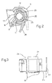
- Figure 2 shows a section of the Figure 1 handle;
- Figure 3 shows a plan view of the Figure 1 handle fitted to a door.
-
- With reference to Figures 1, 2 and 3, number 1 indicates an outside handle of a vehicle. With reference to Figure 3, handle 1 is fitted to a door P comprising a wall P1, and a wall P2 fitted with a known lock mechanism not shown.
- Handle 1 comprises a connecting
body 2 which is fitted to wall P1; a known lever (not shown) hinged to connectingbody 2 and operated, in use, by a user to release the known lock mechanism (not shown); alock assembly 3 which is inserted inside connectingbody 2; and aclamping member 4 designed to assume a clamping position and a release position to clamp and releaselock assembly 3 to and from connectingbody 2. - Connecting
body 2 comprises ashell 5 located at oneend 2a of connectingbody 2 at the corner formed by walls P1 and P2, and which comprises anouter surface 6, and an inner surface 7 defining a through cavity 8 extending axially along an axis A and forhousing lock assembly 3. -
Shell 5 also comprises aseat 9, which extends about axis A, enablesclamping member 4 to be housed partly inside cavity 8, and in turn comprises anopening 10, and twogrooves Opening 10 extends throughshell 5, betweenouter surface 6 and inner surface 7, and permits insertion ofclamping member 4 inside cavity 8. -
Shell 5 comprises twogrooves 13 extending parallel to axis A along inner surface 7 and along the full length of cavity 8; and twocavities outer surface 6 and which are engaged by clampingmember 4 to secureclamping member 4 firmly in the clamping and release positions respectively. -
Lock assembly 3 comprises acylinder 16, and is defined by aportion 17 which is housed inside cavity 8, and by aportion 18 which rests against wall P1 in the clamping position.Portion 17 is defined by a substantially cylindrical surface, from which extend radially twoteeth 19, each of which slides inside arespective groove 13 whenlock assembly 3 is inserted inside or removed from cavity 8. - Clamping
member 4 comprises aring nut 20 and alever 21 integral withring nut 20. -
Ring nut 20 is in the form of a sector and, in use, is inserted insideseat 9 through opening 10 and extends partly inside cavity 8 to partly surroundportion 17. - As shown more clearly in Figure 2,
ring nut 20 is fitted prismatically to grooves 11 and 12, and is guided bygrooves -
Ring nut 20 comprises a curvedouter surface 22; a curvedinner surface 23; two flatlateral surfaces 24; and twoslots 25 extending between the two oppositelateral surfaces 24 atinner surface 23. At eachslot 25,ring nut 20 also comprises arespective wedge 26 integral with alateral surface 24 and having aface 27, which extends from an edge ofrespective slot 25 flush withlateral surface 24, and slopes with respect tolateral surface 24 by an angle of 2 to 20 degrees. -
Lever 21 extends fromouter surface 22 ofring nut 20, projects from opening 10 in use, and comprises alaminar member 28 which is engaged by the user to move clampingmember 4 to or from the clamping or release position; and anelastic retaining member 29 projecting fromlaminar member 28 and having, on the free end, atooth 30 forengaging cavity 14 whenring nut 20 is in the clamping position, andcavity 15 whenring nut 20 is in the release position. - In actual use, commencing from an initial condition in which lock
assembly 3 and connectingbody 2 are separate,ring nut 20 ofclamping member 4 is inserted insideseat 9 through opening 10, and opposite portions ofring nut 20 are inserted insiderespective grooves Ring nut 20 is guided bygrooves tooth 30 of retainingmember 29 engagescavity 15 andslots 25 are aligned withrespective grooves 13 along axis A. At this point,lock assembly 3 is inserted inside cavity 8 in a direction D parallel to axis A by slidingteeth 19 alonggrooves 13 and throughslots 25 so thatring nut 20 is positioned betweenteeth 19 andportion 18 oflock assembly 3, which, in this position, substantially rests against wall P1 of door P. - Once
lock assembly 3 is inserted as described above,clamping member 4 is rotated about axis A by the user liftinglaminar member 28 so as to pushteeth 19, by means ofrespective wedges 26, in direction D and soclamp portion 18 oflock assembly 3 against wall P1, preferably with the interposition of a seal. The clamping position is then secured bytooth 30 of retainingmember 29engaging cavity 14 to prevent any accidental rotation ofclamping member 4. - To remove
lock assembly 3 from connectingbody 2,tooth 30 is simply released fromcavity 14 and clampingmember 4 rotated in the opposite direction usinglaminar member 29, so thatslots 25 are once more aligned withgrooves 13, thus enablinglock assembly 3 to be withdrawn from cavity 8 in direction D. -
Lock assembly 3 is therefore assembled and disassembled extremely easily by simply pressing lightly onlaminar member 28 oflever 21. Moreover, the action ofwedges 26 onteeth 19 oflock assembly 3 ensuresportion 18 oflock assembly 3 rests perfectly in fluidtight manner against wall P1 of the vehicle, or against a seal interposed betweenportion 18 and wall P1. - Clearly, changes may be made to the handle as described herein without, however, departing from the scope of the accompanying Claims.
- For example,
teeth 19 may be of a different number from that described, and may be carried by a cover layer aboutportion 17, or by a ring fixed firmly aboutportion 17. - Moreover,
lever 21 may be formed otherwise than as described without, however, affecting the ease with which the clamping member is operated by the user.
Claims (8)
- A vehicle door handle (1) comprisingsaid handle being characterized in thata connecting body (2) extending along a longitudinal axis and having a seat (8),a lock assembly (3) having a portion (17) insertable inside said seat (8) in a given direction (D), said portion (17) comprising a tooth (19) extending crosswise with respect to said given direction (D); andclamping means (4) for clamping said lock assembly (3) releasably inside said seat (8);
said seat (8) extends along an axis (A) parallel to said direction (D) when inserted inside said seat (8), in that
said connecting body (2) comprises a further seat (9) extending about axis (A) for the clamping means (4) to be partially housed inside said seat (8) and in that
said clamping means (4) comprise a ring nut (20) which rotates about said axis (A) between a first position permitting insertion of said lock assembly (3) and said tooth (19), and a second position for clamping said tooth (19) in said direction (D). - A handle as claimed in Claim 1, characterized in that said ring nut (20) comprises at least one wedge (26) located on a lateral surface (24) of said ring nut (20) and which engages said tooth (19) so as to push said tooth (19) in said given direction (D) by rotating the ring nut (20) about the axis (A).
- A handle as claimed in Claim 2, characterized in that said ring nut comprises a slot (25) permitting passage of said tooth (19), said wedge being located at said slot (25).
- A handle as claimed in any one of the foregoing Claims, characterized in that said clamping means (4) comprise control means (21) for rotating said ring nut (20) about said axis (A).
- A handle as claimed in Claim 4, characterized in that said control means (21) comprise a laminar member (28) engaged by a user and projecting from said connecting body (2); and a retaining member (29) for retaining said clamping means (4) in said first and second position.
- A handle as claimed in any one of the foregoing Claims, characterized in that said seat (8) comprises at least one groove engaged in sliding manner by said tooth (19) to guide said lock assembly (3) in said direction (D) and prevent rotation of said lock assembly (3) about the axis (A).
- A handle as claimed in Claim 3 and 6, characterized in that said slot (25) is alignable with said groove (13) along the axis (A) to permit assembly and disassembly of said lock assembly (3).
- A handle as claimed in any one of the foregoing Claims, characterized in that said lock assembly (3) comprises two teeth; said seat (8) comprising two grooves (13) parallel to each other and to the axis (A) and which are engaged by said teeth; and said ring nut (20) comprising two slots (25) alignable with the respective grooves, and two wedges (26) located on a lateral surface (24) of said ring nut (20) and which engage said teeth (19) so as to push said teeth (19) in said given direction (D).
Applications Claiming Priority (2)
| Application Number | Priority Date | Filing Date | Title |
|---|---|---|---|
| IT1999TO000979A IT1311353B1 (en) | 1999-11-12 | 1999-11-12 | HANDLE OF A DOOR OF A VEHICLE. |
| ITTO990979 | 1999-11-12 |
Publications (2)
| Publication Number | Publication Date |
|---|---|
| EP1099817A1 EP1099817A1 (en) | 2001-05-16 |
| EP1099817B1 true EP1099817B1 (en) | 2004-08-11 |
Family
ID=11418209
Family Applications (1)
| Application Number | Title | Priority Date | Filing Date |
|---|---|---|---|
| EP20000124657 Expired - Lifetime EP1099817B1 (en) | 1999-11-12 | 2000-11-10 | Vehicle door handle |
Country Status (4)
| Country | Link |
|---|---|
| EP (1) | EP1099817B1 (en) |
| DE (1) | DE60012848T2 (en) |
| ES (1) | ES2226687T3 (en) |
| IT (1) | IT1311353B1 (en) |
Families Citing this family (10)
| Publication number | Priority date | Publication date | Assignee | Title |
|---|---|---|---|---|
| DE10036398A1 (en) * | 2000-07-26 | 2002-02-28 | Volkswagen Ag | Device for locking a lock cylinder housing |
| FR2846692B1 (en) * | 2002-10-31 | 2005-07-22 | Fabi Automobile | APPARATUS FOR THE INVIOLABLE MOUNTING OF LOCK LOCK OF A LOCK IN AN EXTERIOR DOOR OPENING CONTROL OF A VEHICLE |
| DE10327081A1 (en) * | 2003-06-13 | 2005-01-13 | Daimlerchrysler Ag | Handle fitting for doors or flaps of vehicles |
| DE102004001894B4 (en) * | 2004-01-14 | 2006-03-23 | Daimlerchrysler Ag | Actuation device for doors or flaps on vehicles |
| DE102004029768B4 (en) * | 2004-06-21 | 2006-03-30 | Audi Ag | Structure for securing device of lock cylinder in vehicle door has locking element in contact with clamp-like device, whereby clamp-like device is fixed between lock cylinder and locking element |
| ITMI20041807A1 (en) | 2004-09-21 | 2004-12-21 | Valeo Sicurezza Abitacolo Spa | GOALKEEPER HANDLE AND ASSEMBLY PROCEDURE |
| ITMI20062252A1 (en) * | 2006-11-24 | 2008-05-25 | Valeo Sicurezza Abitacolo Spa | HANDLE FOR VEHICLE DOORS AS WELL AS TOOL AND PROCEDURES FOR MOUNTING OR DISASSEMBLING THIS HANDLE |
| IT1396958B1 (en) | 2009-12-18 | 2012-12-20 | Valeo Spa | VEHICLE DOOR HANDLE INCLUDING A GAME RECOVERY |
| ITMI20101367A1 (en) * | 2010-07-23 | 2012-01-23 | Valeo Spa | VEHICLE DOOR HANDLE INCLUDING A BRACKET AND A HOLDING ORGAN |
| FR3114118B1 (en) * | 2020-09-15 | 2023-04-14 | Renault Sas | Opening control device for a door of a motor vehicle. |
Family Cites Families (4)
| Publication number | Priority date | Publication date | Assignee | Title |
|---|---|---|---|---|
| US2040258A (en) * | 1934-08-27 | 1936-05-12 | Briggs & Stratton Corp | Mounting means for automobile doorlocks |
| JPS5931633B2 (en) * | 1980-07-29 | 1984-08-03 | 日産自動車株式会社 | Automotive door handle device |
| FR2589510B1 (en) * | 1985-10-30 | 1987-12-18 | Neiman Sa | BAYONET MOUNT LOCK |
| GB2281341A (en) * | 1993-08-28 | 1995-03-01 | Ford Motor Co | Securing a lock barrel to a vehicle door |
-
1999
- 1999-11-12 IT IT1999TO000979A patent/IT1311353B1/en active
-
2000
- 2000-11-10 ES ES00124657T patent/ES2226687T3/en not_active Expired - Lifetime
- 2000-11-10 EP EP20000124657 patent/EP1099817B1/en not_active Expired - Lifetime
- 2000-11-10 DE DE60012848T patent/DE60012848T2/en not_active Expired - Lifetime
Also Published As
| Publication number | Publication date |
|---|---|
| ITTO990979A1 (en) | 2001-05-12 |
| ITTO990979A0 (en) | 1999-11-12 |
| DE60012848D1 (en) | 2004-09-16 |
| DE60012848T2 (en) | 2005-08-18 |
| ES2226687T3 (en) | 2005-04-01 |
| IT1311353B1 (en) | 2002-03-12 |
| EP1099817A1 (en) | 2001-05-16 |
Similar Documents
| Publication | Publication Date | Title |
|---|---|---|
| US5443276A (en) | Self-locking blade holder | |
| EP1099817A1 (en) | Vehicle door handle | |
| US6112420A (en) | Blade clamp for reciprocating saw | |
| JPH0266308A (en) | Assembly tool | |
| CN107407102B (en) | The device of holding element for handle for doors and windows and the handle for doors and windows in the receiving opening in window frame, door leaf or the like | |
| US4549831A (en) | Set of joining hardware | |
| US5109685A (en) | Control key for extension adapter | |
| US6823703B2 (en) | Removable plug cylinder lock | |
| CN1926369A (en) | Sanitary fitting | |
| CA1269501A (en) | Toilet push button front/side lever | |
| EP1643176A2 (en) | Valve lockout assembly | |
| KR200160156Y1 (en) | Pull handle door lock device | |
| JP3370299B2 (en) | Locking device with lock | |
| FR2808832A1 (en) | Lock fitting, for sliding door or window, is bedded in hole mounting, and fixed by rotating clamp operated by tool through access hole in nose plate | |
| JPH08244628A (en) | Fixing device for handle-hub of automobile onto handle shaft | |
| WO2002042588A1 (en) | A locking mechanism | |
| US3099472A (en) | Rim lock set | |
| EP1074772A1 (en) | Ball valve with key-operated lock | |
| US4602704A (en) | Fastening device for a bicycle brake block | |
| KR200255992Y1 (en) | nut | |
| JP4597760B2 (en) | Fixing nut | |
| JP4712770B2 (en) | Plug-in fixed holder for circuit breaker | |
| AU2009211963A1 (en) | Device for securing an installation box to an opening in a wall shell | |
| EP1306169B1 (en) | Pipe clamping jaw with fast fitting and removable adapter | |
| JP7426747B1 (en) | door handle device |
Legal Events
| Date | Code | Title | Description |
|---|---|---|---|
| PUAI | Public reference made under article 153(3) epc to a published international application that has entered the european phase |
Free format text: ORIGINAL CODE: 0009012 |
|
| AK | Designated contracting states |
Kind code of ref document: A1 Designated state(s): DE ES FR GB SE |
|
| AX | Request for extension of the european patent |
Free format text: AL;LT;LV;MK;RO;SI |
|
| 17P | Request for examination filed |
Effective date: 20011113 |
|
| AKX | Designation fees paid |
Free format text: DE ES FR GB SE |
|
| 17Q | First examination report despatched |
Effective date: 20020729 |
|
| GRAP | Despatch of communication of intention to grant a patent |
Free format text: ORIGINAL CODE: EPIDOSNIGR1 |
|
| GRAS | Grant fee paid |
Free format text: ORIGINAL CODE: EPIDOSNIGR3 |
|
| GRAA | (expected) grant |
Free format text: ORIGINAL CODE: 0009210 |
|
| AK | Designated contracting states |
Kind code of ref document: B1 Designated state(s): DE ES FR GB SE |
|
| REG | Reference to a national code |
Ref country code: GB Ref legal event code: FG4D |
|
| REF | Corresponds to: |
Ref document number: 60012848 Country of ref document: DE Date of ref document: 20040916 Kind code of ref document: P |
|
| PG25 | Lapsed in a contracting state [announced via postgrant information from national office to epo] |
Ref country code: GB Free format text: LAPSE BECAUSE OF NON-PAYMENT OF DUE FEES Effective date: 20041111 Ref country code: SE Free format text: LAPSE BECAUSE OF FAILURE TO SUBMIT A TRANSLATION OF THE DESCRIPTION OR TO PAY THE FEE WITHIN THE PRESCRIBED TIME-LIMIT Effective date: 20041111 |
|
| ET | Fr: translation filed | ||
| REG | Reference to a national code |
Ref country code: ES Ref legal event code: FG2A Ref document number: 2226687 Country of ref document: ES Kind code of ref document: T3 |
|
| PLBE | No opposition filed within time limit |
Free format text: ORIGINAL CODE: 0009261 |
|
| STAA | Information on the status of an ep patent application or granted ep patent |
Free format text: STATUS: NO OPPOSITION FILED WITHIN TIME LIMIT |
|
| GBPC | Gb: european patent ceased through non-payment of renewal fee |
Effective date: 20041111 |
|
| 26N | No opposition filed |
Effective date: 20050512 |
|
| REG | Reference to a national code |
Ref country code: FR Ref legal event code: PLFP Year of fee payment: 16 |
|
| REG | Reference to a national code |
Ref country code: ES Ref legal event code: PC2A Owner name: U-SHIN ITALIA S.P.A. Effective date: 20160427 |
|
| REG | Reference to a national code |
Ref country code: FR Ref legal event code: PLFP Year of fee payment: 17 |
|
| REG | Reference to a national code |
Ref country code: DE Ref legal event code: R082 Ref document number: 60012848 Country of ref document: DE Representative=s name: PRINZ & PARTNER MBB PATENTANWAELTE RECHTSANWAE, DE Ref country code: DE Ref legal event code: R081 Ref document number: 60012848 Country of ref document: DE Owner name: U-SHIN ITALIA S.P.A., IT Free format text: FORMER OWNER: VALEO SICUREZZA ABITACOLO S.P.A., SANTENA, IT |
|
| REG | Reference to a national code |
Ref country code: FR Ref legal event code: PLFP Year of fee payment: 18 |
|
| PGFP | Annual fee paid to national office [announced via postgrant information from national office to epo] |
Ref country code: DE Payment date: 20181112 Year of fee payment: 19 |
|
| PGFP | Annual fee paid to national office [announced via postgrant information from national office to epo] |
Ref country code: ES Payment date: 20181220 Year of fee payment: 19 Ref country code: FR Payment date: 20181129 Year of fee payment: 19 |
|
| REG | Reference to a national code |
Ref country code: DE Ref legal event code: R119 Ref document number: 60012848 Country of ref document: DE |
|
| PG25 | Lapsed in a contracting state [announced via postgrant information from national office to epo] |
Ref country code: FR Free format text: LAPSE BECAUSE OF NON-PAYMENT OF DUE FEES Effective date: 20191130 Ref country code: DE Free format text: LAPSE BECAUSE OF NON-PAYMENT OF DUE FEES Effective date: 20200603 |
|
| REG | Reference to a national code |
Ref country code: ES Ref legal event code: FD2A Effective date: 20210414 |
|
| PG25 | Lapsed in a contracting state [announced via postgrant information from national office to epo] |
Ref country code: ES Free format text: LAPSE BECAUSE OF NON-PAYMENT OF DUE FEES Effective date: 20191111 |