EP1098218A2 - Verfahren zum Wiedergeben von Bildsignalwerten - Google Patents
Verfahren zum Wiedergeben von Bildsignalwerten Download PDFInfo
- Publication number
- EP1098218A2 EP1098218A2 EP00123874A EP00123874A EP1098218A2 EP 1098218 A2 EP1098218 A2 EP 1098218A2 EP 00123874 A EP00123874 A EP 00123874A EP 00123874 A EP00123874 A EP 00123874A EP 1098218 A2 EP1098218 A2 EP 1098218A2
- Authority
- EP
- European Patent Office
- Prior art keywords
- value
- pixel
- control signal
- color
- values
- Prior art date
- Legal status (The legal status is an assumption and is not a legal conclusion. Google has not performed a legal analysis and makes no representation as to the accuracy of the status listed.)
- Withdrawn
Links
- 238000000034 method Methods 0.000 title claims description 45
- 230000008859 change Effects 0.000 claims description 88
- 238000006243 chemical reaction Methods 0.000 claims description 13
- 238000005562 fading Methods 0.000 claims description 6
- 238000012545 processing Methods 0.000 description 22
- 239000003086 colorant Substances 0.000 description 11
- 230000008569 process Effects 0.000 description 7
- 238000011161 development Methods 0.000 description 5
- 238000012546 transfer Methods 0.000 description 4
- 239000000203 mixture Substances 0.000 description 2
- 230000007704 transition Effects 0.000 description 2
- 239000000654 additive Substances 0.000 description 1
- 230000000996 additive effect Effects 0.000 description 1
- 238000012512 characterization method Methods 0.000 description 1
- 238000004737 colorimetric analysis Methods 0.000 description 1
- 230000007423 decrease Effects 0.000 description 1
- 238000010586 diagram Methods 0.000 description 1
- 230000000694 effects Effects 0.000 description 1
- 230000006870 function Effects 0.000 description 1
- 230000004048 modification Effects 0.000 description 1
- 238000012986 modification Methods 0.000 description 1
- 238000009877 rendering Methods 0.000 description 1
Images




Classifications
-
- G—PHYSICS
- G09—EDUCATION; CRYPTOGRAPHY; DISPLAY; ADVERTISING; SEALS
- G09G—ARRANGEMENTS OR CIRCUITS FOR CONTROL OF INDICATING DEVICES USING STATIC MEANS TO PRESENT VARIABLE INFORMATION
- G09G5/00—Control arrangements or circuits for visual indicators common to cathode-ray tube indicators and other visual indicators
- G09G5/02—Control arrangements or circuits for visual indicators common to cathode-ray tube indicators and other visual indicators characterised by the way in which colour is displayed
- G09G5/06—Control arrangements or circuits for visual indicators common to cathode-ray tube indicators and other visual indicators characterised by the way in which colour is displayed using colour palettes, e.g. look-up tables
-
- G—PHYSICS
- G09—EDUCATION; CRYPTOGRAPHY; DISPLAY; ADVERTISING; SEALS
- G09G—ARRANGEMENTS OR CIRCUITS FOR CONTROL OF INDICATING DEVICES USING STATIC MEANS TO PRESENT VARIABLE INFORMATION
- G09G2340/00—Aspects of display data processing
- G09G2340/02—Handling of images in compressed format, e.g. JPEG, MPEG
-
- G—PHYSICS
- G09—EDUCATION; CRYPTOGRAPHY; DISPLAY; ADVERTISING; SEALS
- G09G—ARRANGEMENTS OR CIRCUITS FOR CONTROL OF INDICATING DEVICES USING STATIC MEANS TO PRESENT VARIABLE INFORMATION
- G09G5/00—Control arrangements or circuits for visual indicators common to cathode-ray tube indicators and other visual indicators
- G09G5/36—Control arrangements or circuits for visual indicators common to cathode-ray tube indicators and other visual indicators characterised by the display of a graphic pattern, e.g. using an all-points-addressable [APA] memory
- G09G5/39—Control of the bit-mapped memory
Definitions
- the invention relates to a method for reproducing image signal values Pixels of a sequence of pixels on a display device using digital image control signals the word length M bit via digital control signals of the shorter word length N bit, for which a current pixel corresponds to its image signal values the first digital control signal is transmitted, the first digital control signal the current pixel according to a saved conversion rule is converted into the corresponding digital image control signal, and in which the display device for the current pixel corresponding image signal values reproduces the digital image control signal.
- Such a method can be used wherever on a viewing device, such as. a monitor or an LCD display, pixel-by-pixel colors should be. Such a method is also additional or alternative Can be used to control the brightness pixel by pixel.
- a viewing device such as. a monitor or an LCD display
- Such a method is also additional or alternative Can be used to control the brightness pixel by pixel.
- Images are displayed pixel by pixel on the display device.
- the color and / or Brightness values of the individual pixels are also called image signal values designated.
- the image signal values of the individual pixels are marked with a the shorter word length N bits reduced storage space requirement, according to the conversion rule into the corresponding digital image control signal the longer word length is converted to M bit and then on the display device shown.
- RGB color display is usually on a display device used.
- the color of the respective pixel is determined by additive Mixture of the primary colors red, green and blue created by international Agreement are established. Red has a wavelength of 700 nm, green the wavelength is 546.1 nm, and blue is the wavelength 435.8 nm.
- R, G, B are trichromatic color measure numbers, hereinafter called color values R, G, B, the Specify amounts with which the primary colors red, green, blue on the mixture the color are involved.
- the individual color values R, G, B take on the computer-assisted Processing only discrete values.
- truecolor display becomes the characterization of the color for each basic color a digital value of the word length 8 bits is used as the color value R, G, B For each Accordingly, the pixel becomes a storage space for a value of the word length 24 bit required.
- FIG. 1 shows an arrangement for reproducing the color values R, G, B of a current one Pixel according to this true color system.
- An image processing system 10 is connected to a signal line with a D / A converter 12, 14, 16, whose analog outputs are each connected to a display device 18.
- Everyone D / A converter 12, 14, 16 belongs to a color value R, G, B and can be digital Convert 8-bit word values into an analog value.
- the color values R, G, B as a value of the total Word length 24 bits each in component form via the signal lines to the D / A converter 12, 14, 16 transmit the respective color value R, G, B in each case convert analog signal and transmit it to the display device 18.
- the viewing device 18 are pixel by pixel corresponding to those of the D / A converters 12, 14, 16 transmitted analog signals the color values of a current pixel again.
- An arrangement for displaying the brightness value of a current one Pixel is similar to the arrangement shown in Fig. 1 for playback the color values R, G, B, the brightness value being like a color value, e.g. how the color value R is processed.
- the brightness value is processed in accordance with a color value for every pixel, i.e. the brightness value is in a separate arrangement processes similar to that which processes the color value R.
- Fig. 2 shows a known arrangement for reducing the processing effort and the storage space requirement for a pixel.
- An image processing system 20 is with a signal line with a so-called CLUT module 22 (Color Lookup Table).
- the CLUT module 22 is via a signal line in each case connected to the D / A converters 12, 14, 16.
- the D / A converter 12, 14, 16 and the display device 18 correspond to those of FIG. 1.
- the image processing system 20 transmits a digital one for the color values of a current pixel Control signal of word length 8 bits via the signal line to the CLUT module 22.
- the CLUT module 22 is the for each transmitted control signal Word length 8 bits an assignment to the color values R, G, B stored at for each color value R, G, B a digital value of the word length 8 bits is stored.
- the individual color values R, G, B are digital Transmit values of the word length of 8 bits each to the D / A converters 12, 14, 16, which convert them into corresponding analog signals.
- the display device 18 gives the color value of a current pixel according to these analog signals again.
- This arrangement is compared to the arrangement 1 requires only a third of the storage space, because for the color values R, G, B of the individual pixels only one digital control signal of the word length 8 bits instead of three color values R, G, B with a word length of 8 each Bit of a total word length of 24 bits is stored and processed.
- Fig. 3 shows an example of such a color level instead of a desired color gradient.
- Five pixels P1 to P5 are shown.
- the pixel P1 should have the color F 1 with the color values R 1 , G 1 , B 1 and the pixel P5 the color F 2 with the color values R 2 , G 2 , B 2 .
- the object is achieved in a method of the type mentioned at the outset by that the first digital control signal for at least one pixel Change value corresponds, and that the display device for the at least one pixel reproduces at least one image signal intermediate value which corresponds to the according to the Change value corresponds to the changed image signal value of the previous pixel.
- the display device gives at least one a pixel an intermediate signal value again.
- the at least one Pixel is not the first digital control signal with the word length N bit Image signal value of the pixel, but its change value compared to that previous pixel saved. In this way, starting from that Image signal value of the previous pixel the change in the word length N bits can be reproduced. Without the Space requirements for the individual pixel of the pixel sequence changes, can in this way all image signal values reproducible by the display device by changing the image signal value of the previous pixel according to the Change value of the current pixel are reproduced.
- the image signal values are color signal values or brightness signal values.
- a further development of the invention is characterized in that the first digital Control signal a first portion, the image signal value or the change value and has a second portion that determines whether the first Share corresponds to the image signal value or the change value.
- the first digital Control signal a first portion, the image signal value or the change value and has a second portion that determines whether the first Share corresponds to the image signal value or the change value.
- the first digital drive signal is enough Bit of the first digital drive signal to determine whether the remaining ones Digits, i.e. the first part is the image signal value or the change value corresponds. So the first part can simply be the image signal value or the change value assign. Without changing the storage space this way enlarged, intermediate image signal values can be corresponding to a word length up to control to N-1 bit.
- the change value is based on the conversion rule converted into a digital change control signal.
- the digital image control signal of the respective preceding pixel is preferably saved. Because this digital image control signal is already in accordance with the digital change control signal may have changed increases additionally the number of controllable colors and / or controllable colors Brightness values.
- At least one pixel is used transmit second digital control signal. This way, if necessary second information required for one or more pixels digital control signal are transmitted. The space requirement increases then only for the at least one pixel. The remaining pixels do not require additional storage space.
- the second digital control signal can then correspond to a change start value.
- the image signal value of a pixel can not only but based on the image signal value of the previous pixel can also be changed based on the change start value. This will the procedure can be used more flexibly.
- a further development is characterized in that the display device for the at least a pixel reproduces an image signal intermediate value, which according to corresponds to the change value changed change start value.
- the display device for the at least a pixel reproduces an image signal intermediate value, which according to corresponds to the change value changed change start value.
- the display device for the at least a pixel reproduces an image signal intermediate value, which according to corresponds to the change value changed change start value.
- the display device for the at least a pixel reproduces an image signal intermediate value, which according to corresponds to the change value changed change start value.
- the first and the second digital control signal should each have one have a third share.
- This third part can then serve the Working method required for the first or the second digital control signal to control.
- the third component preferably determines whether the digital control signal is the first or is the second digital control signal.
- 1 bit of the total N bit is sufficient of the first and the second digital control signal in each case for determination out.
- the storage space requirement for a pixel does not increase, and the number of controllable colors and / or brightness values only decreases marginally.
- a further development of the invention is characterized in that the first part of the second control signal corresponds to the change start value.
- the change start value according to the conversion rule into a digital one Change start signal converted.
- the existing Conversion logic also used to convert the change seed and no additional components are required.
- Fig. 4 shows a first embodiment of an arrangement for playback the color values of a current pixel of a pixel sequence.
- the D / A converter 12, 14, 16 and the display device 18 correspond to those according to FIG. 1.
- An image processing system 30 is with two signal lines S1, S2 with a CLUT module 32 connected.
- the CLUT module 32 is each with a signal line with the change modules 34, 36, 38 connected, each with the signal line S2 also are connected.
- the change modules 34, 36, 38 are with the D / A converter 12, 14, 16 each connected.
- the image processing system 30 transmits the digital drive signal of the word length 8 bits for a current pixel of a pixel sequence via the signal lines S1, S2 to the CLUT module.
- a first part of the word length becomes 7 Bit of the digital control signal via the signal line S1 to the CLUT module 32 transfer.
- a second part of the word length 1 bit of the digital control signal is also sent to the. as a first control signal SS1 via the signal line S2 Transfer CLUT module 32.
- the second share is going to one Transfer the input of the change modules 34, 36, 38.
- the first control signal SS1 indicates whether the first portion is to be further processed as a color value or as a change value is.
- 128 colors corresponding to the remaining word length 7 bits are stored as sets of color values R, G, B each with the word length 8 bits and as 128 change sets I R , I G , I B also with the word length 8 bits.
- the first control signal SS1 has the binary value 1
- a set of color values R, G, B is selected in accordance with the value of the first portion and passed on component-wise to the change modules 34, 36, 38, which each transfer the color values for R, G, B to Forward D / A converter 12, 14, 16.
- the D / A converters 12, 14, 16 convert the digital color values R, G, B into analog signals in a known manner and pass them on to the display device 18.
- the display device 18 reproduces the color values R, G, B of the current pixel in accordance with the analog signals.
- a change set I R , I G , I B is selected in accordance with the first portion of the digital control signal by the CLUT module 32 and forwarded component by component to the change modules 34, 36, 38, respectively.
- the value 0 of the first control signal SS1 is also transmitted to the change modules 34, 36, 38, respectively.
- the change modules 34, 36, 38 each change the color value R, G, B of the previous pixel by the change value I R , I G , I B , as described in more detail below.
- the color values R, G, B changed in this way are each transmitted to the D / A converters 12, 14, 16, converted into an analog signal and fed to the display device 18.
- the display device 18 then reproduces the changed color values for the current pixel.
- the change module 34 has a multiplexer 40, a register 42 and an adder 44.
- the control input of the multiplexer 40 is with the signal line S2 with the image processing system 30 in FIG. 4 connected.
- One input of the multiplexer 40 is directly with the CLUT module 32 connected.
- the other input of multiplexer 40 is with the output of the adder 44 connected, one input of which is also connected to the CLUT module 32 in Connection is established.
- the output of the multiplexer 40 is with the buffer 42 connected, the output of which is connected to the D / A converter 12 and to the other Input of the adder 44 is connected.
- the CLUT module 32 selects according to the first component of the digital control signal a value of the word length 8 bits for the color value R. and forwards this color value R to the multiplexer 40.
- the value 1 of the first Control signal SS1 is also sent to the control input of multiplexer 40 transferred, which then forwards the color value R to the buffer 42.
- the buffer store 42 stores the color value R as the output value for a color change for the subsequent pixel and also leads the Color value R to the D / A converter 12 on.
- the register 42 stores the sum R + I R transmitted by the multiplexer 40 as an output value for the subsequent pixel and additionally transmits this sum R + I R as a color value R ′ to the D / A converter 12.
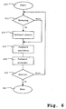
- FIG. 6 shows a flowchart of the method for reproducing the color values of a current pixel, as is carried out by the arrangement described above.
- the method is started in step S10.
- the first control signal SS1 is then checked in step S12 to determine whether a change value I R , I G , I B has been transmitted to the arrangement. If this is not the case, the currently transmitted color value R, G, B is stored in step S 14 next.
- the color values R, G, B of the current pixel are then reproduced on the display device 18 in step S16.
- step S18 follows next.
- step S18 the color values R, G, B of the previous pixel are changed component by component in accordance with the transferred change values. Step S14 then also follows.
- step S20 After the respective color value is reproduced on the display device 18 in step S16 has been checked, it is checked in step S20 whether the method is terminated shall be. If this is the case, the method is next ended in step S22. Otherwise, the process branches back to step S12.
- FIG. 7 shows five pixels P6 to P10 of a pixel sequence which has been reproduced according to the first exemplary embodiment. 3, the pixel P6 should have the color F 1 with the color values R 1 , G 1 , B 1 and the pixel P10 the color F 2 with the color values R 2 , G 2 , B 2 .
- the color value R the following is intended to show how a desired color gradient from R 1 to R 2 can be reproduced in the pixels P7, P8, P9.
- the display device 18 After the value 1 for the first control signal SS1 and the color value R 1 corresponding to the first component of the digital control signal has been previously transmitted to the change module 34 for the pixel P6, the display device 18 has reproduced the color value R 1 in the pixel P6 and the register 42 has stored the color value R 1 .
- the value 0 for the first control signal SS1 and the change value I R1 corresponding to the first component of the digital control signal are transmitted to the change module 34.
- the adder 44 then adds the change value I R1 to the color value R 1 .
- the sum R 1 + I R1 is stored as the color value R v1 in the register 42 and reproduced by the display device 18 in the pixel P7.
- the first control signal SS1 1 for the pixel P10 and the color value R 2 is reproduced.
- Fig. 8 shows a second embodiment of an arrangement for playback the color values of a current pixel.
- the D / A converter 12, 14, 16 and that Viewing device 18 correspond to those described above.
- An image processing system 50 is connected to a CLUT module 52, each with three Signal lines with change modules 54, 56, 58 is connected.
- the change modules 54, 56, 58 are connected to the D / A converters 12, 14, 16, respectively. The function of this arrangement is described in more detail below with reference to FIG. 9 received.
- FIG. 9 shows the change module 54 for the color value R according to FIG. 8.
- the change modules 56, 58 for the color values G, B have the same structure.
- An output of the CLUT module 52 is directly with the D / A converter 12 and connected to a multiplexer 60.
- Another input of multiplexer 60 is connected to a further output of the CLUT module 52, the additional is connected to a module 62.
- a third output of the CLUT module 52 is connected to an adder 64 and to another module 66.
- the second The input of the adder 64 is connected to the output of the multiplexer 60.
- the outputs of the modules 62, 66 are each with a control input of the multiplexer 60 and connected to the inputs of an OR gate 68.
- the output of the adder 64 is connected to a buffer memory 70, its output with a third input of multiplexer 60 and with the input a so-called tristate buffer 72 is connected.
- the control input of the Tristate buffer 72 is connected to OR gate 68.
- the exit of the tri-state buffer 72 is connected to the D / A converter 12 and to the multiplexer 60.
- two portions of the image processing system 50 to the CLUT module 52 transmitted digital control signal used as a first and a second control signal SS1, SS2.
- the first Control signal SS1 has the value 1, denotes the remaining portion of the digital Control signal the color values R, G, B of the current pixel.
- the CLUT module 52 the color value R of the word length 8 bits to the Multiplexer 60 and transmitted to the D / A converter 12.
- the first control signal SS1 has the value 0, this identifies the remaining portion of the digital control signal as a change signal.
- a change value I R of the word length 8 bits is transmitted to the adder 64 and to the module 66.
- the module 66 passes the binary value 1 to the multiplexer 60 and to the OR module 68 when it is determined that a change value I R has been transmitted.
- the adder 64 then adds the change value I R to the color value R of the preceding pixel and passes this sum on to the buffer store 70.
- the buffer 70 stores this value and also forwards it to the tri-state buffer 72.
- OR gate 68 receives the binary value 1 from the module 66 or from the module 62, there is also a binary value 1 passed on to the control input of the tri-state buffer 72, which then transmits the value stored in the buffer memory 70 to the D / A- Transducer 12 forwards.
- the CLUT module 52 forwards a change start value R 0 of the word length 8 bits to the multiplexer 60 and to the module 62 in accordance with the remaining portion of the digital control signal.
- the module 62 then passes the binary value 1 on to the multiplexer 60 and to the OR gate 68.
- the multiplexer 60 passes on the change start value R 0 to the adder 64, which subsequently adds the change value I R and stores the value obtained in this way in the memory 70 and forwards it to the D / A converter 12 via the tristate buffer 72.
- the modules 62, 66 can also be omitted if the control signals SS1, SS2 are used directly to control the multiplexer 60 and the OR gate 68.
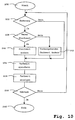
- step S30 the process started.
- step S32 the first control signal SS1 checks whether a change should be made. Isn't that If so, the currently transmitted color value R, G, B is stored in step S34 next and displayed on the display device 18 in step S36.
- step S32 If it is recognized in step S32 from the value of the first control signal SS1 that a change to be made is next performed in step S38 Checking the second control signal SS2 determined whether a new change start value is present. If this is the case, the change start value next becomes in step S40 changed by the change value. This is followed by step S34.
- step S38 If it is determined in step S38 that there is no new start value, as next in step S42 the color value R, G, B of the previous pixel by changed the change value. This is also followed by step S34.
- Step S44 After displaying the color image on the display 18 in step S36 follows Step S44. Here it is checked whether the process should be ended. Is that the If so, the process is next ended in step S46. Otherwise it will go back branches to step S32.
- Fig. 11 shows a third embodiment of an arrangement for playback the color values R, G, B of a current pixel.
- the image processing system 50 controls a CLUT module 74, which in turn the change modules 54, 56, 58 and 76, 78, 80 each controls, the Output of the change module 54, 56, 58 each with an input of the change module 76, 78, 80 is connected.
- the arrangements and described in the embodiments of FIGS. 4 to 11 Process for processing and reproducing the color values R, G, B of a current Pixels can also be processed and reproduced in the same way of brightness values.
- the brightness signal can be in one separate arrangement or in an additional fourth processing branch of the Arrangements of FIGS. 4 to 11 are processed.
- the brightness signal will processed like one of the color signals R, G or B.
- processing the brightness signal using a separate arrangement has this arrangement preferably only one processing branch, e.g. the processing branch for the color signal R corresponds to FIGS. 4 to 11.
Landscapes
- Engineering & Computer Science (AREA)
- Physics & Mathematics (AREA)
- Computer Hardware Design (AREA)
- General Physics & Mathematics (AREA)
- Theoretical Computer Science (AREA)
- Processing Of Color Television Signals (AREA)
- Color Television Systems (AREA)
Abstract
Description
- Fig. 1
- eine Anordnung zum Wiedergeben der Farbwerte eines aktuellen Bildpunktes einer Bildpunktfolge mittels digitaler Farbsteuersignale über Ansteuersignale der gleichen Wortlänge,
- Fig. 2
- eine bekannte Anordnung zum Wiedergeben der Farbwerte eines aktuellen Bildpunktes einer Bildpunktfolge mittels digitaler Farbsteuersignale über digitale Ansteuersignale einer kürzeren Wortlänge,
- Fig. 3
- fünf Bildpunkte einer Bildpunktfolge, deren Farbwerte entsprechend der Anordnung nach Fig. 2 wiedergegeben worden sind,
- Fig. 4
- eine Anordnung zum Wiedergeben der Farbwerte eines aktuellen Bildpunktes einer Bildpunktfolge als erstes Ausführungsbeispiel der Erfindung,
- Fig. 5
- eine schematische Ansicht eines Änderungsmoduls der Anordnung nach Fig. 4,
- Fig. 6
- ein Flußdiagramm des Verfahrens zum Wiedergeben der Farbwerte eines aktuellen Bildpunktes einer Bildpunktfolge nach dem ersten Ausführungsbeispiel,
- Fig. 7
- fünf Bildpunkte einer Bildpunktfolge, die nach dem ersten Ausführungsbeispiel wiedergegeben worden ist,
- Fig. 8
- ein zweites Ausführungsbeispiel einer Anordnung zum Wiedergeben der Farbwerte eines aktuellen Bildpunktes einer Bildpunktfolge,
- Fig. 9
- eine erfindungsgemäße Änderungseinheit nach Fig. 8,
- Fig. 10
- ein Flußdiagramm des Verfahrens zum Wiedergeben der Farbwerte eines aktuellen Bildpunktes einer Bildpunktfolge nach dem zweiten Ausführungsbeispiel, und
- Fig. 11
- ein drittes Ausführungsbeispiel einer Anordnung zum Wiedergeben der Farbwerte eines aktuellen Bildpunktes einer Bildpunktfolge.
Claims (15)
- Verfahren zum Wiedergeben der Bildsignalwerte (R, G, B) der Bildpunkte einer Bildpunktfolge auf einem Sichtgerät (18) mittels digitaler Bildsteuersignale der Wortlänge M Bit über digitale Ansteuersignale der kürzeren Wortlange N Bit,bei dem für einen aktuellen Bildpunkt ein seinen Bildsignalwerten (R, G, B) entsprechendes erstes digitales Ansteuersignal übertragen wird,das erste digitale Ansteuersignal des aktuellen Bildpunktes nach einer gespeicherten Umwandlungsvorschrift in das entsprechende digitale Bildsteuersignal umgewandelt wird, undbei dem das Sichtgerät (18) für den aktuellen Bildpunkt Bildsignalwerte (R, G, B) entsprechend dem digitalen Bildsteuersignal wiedergibt,
dadurch gekennzeichnet, daßdas erste digitale Ansteuersignal für mindestens einen Bildpunkt einem Änderungswert entspricht, unddaß das Sichtgerät (18) für den mindestens einen Bildpunkt mindestens einen Bildsignalzwischenwert (Fv1, Fv2, Fv3) wiedergibt, der dem gemäß dem Änderungswert geänderten Bildsignalwert (F) des vorhergehenden Bildpunktes entspricht. - Verfahren nach Anspruch 1, dadurch gekennzeichnet, daß das Verfahren zum Wiedergeben von Farbwerten (R, G, B) dient, daß die Bildsteuersignale Farbsteuersignale sind, daß die Bildsignalwerte Farbwerte sind, und daß die Bildsignalzwischenwerte Farbzwischenwerte sind.
- Verfahren nach Anspruch 1 oder 2, dadurch gekennzeichnet, daß das Verfahren zum Wiedergeben von Helligkeitswerten dient, daß die Bildsteuersignale Helligkeitssteuersignale sind, daß die Bildsignalwerte Helligkeitswerte sind, und daß die Bildsignalzwischenwerte Helligkeitszwischenwerte sind.
- Verfahren nach einem der vorhergehenden Ansprüche, dadurch gekennzeichnet, daß das erste digitale Ansteuersignal einen ersten Anteil, der dem Bildsignalwert (R, G, B) oder dem Änderungswert entspricht, und einen zweiten Anteil (SS1) hat, der bestimmt, ob der erste Anteil dem Bildsignalwert (R, G, B) oder dem Änderungswert entspricht.
- Verfahren nach Anspruch 4, dadurch gekennzeichnet, daß der Änderungswert nach der Umwandlungsvorschrift in ein digitales Änderungssteuersignal (IR) umgewandelt wird.
- Verfahren nach einem der vorhergehenden Ansprüche, dadurch gekennzeichnet, daß das digitale Bildsteuersignal des jeweils vorhergehenden Bildpunktes gespeichert wird.
- Verfahren nach einem der vorhergehenden Ansprüche, dadurch gekennzeichnet, daß der Änderungswert, eine Summe von Änderungswerten und/oder ein Änderungsstartwert gespeichert wird.
- Verfahren nach einem der vorhergehenden Ansprüche, dadurch gekennzeichnet, daß für mindestens einen Bildpunkt ein zweites digitales Ansteuersignal übertragen wird.
- Verfahren nach Anspruch 8, dadurch gekennzeichnet, daß das zweite digitale Ansteuersignal einem Änderungsstartwert entspricht.
- Verfahren nach Anspruch 9, dadurch gekennzeichnet, daß das Sichtgerät (18) für den mindestens einen Bildpunkt einen Bildsignalzwischenwert wiedergibt, der dem gemäß dem Änderungswert (IR) geänderten Änderungsstartwert entspricht.
- Verfahren nach einem der Ansprüche 8 bis 10, dadurch gekennzeichnet, daß das erste und das zweite digitale Ansteuersignal jeweils einen dritten Anteil (SS2) haben.
- Verfahren nach Anspruch 11, dadurch gekennzeichnet, daß der dritte Anteil (SS2) bestimmt, ob das digitale Ansteuersignal das erste oder das zweite digitale Ansteuersignal ist.
- Verfahren nach einem der Ansprüche 8 bis 12, dadurch gekennzeichnet, daß der erste Anteil des zweiten Ansteuersignals dem Änderungsstartwert entspricht.
- Verfahren nach Anspruch 13, dadurch gekennzeichnet, daß der Änderungsstartwert nach der Umwandlungsvorschrift in ein digitales Änderungsstartsignal (R0) umgewandelt wird.
- Verfahren nach einem der vorhergehenden Ansprüche, dadurch gekennzeichnet, daß das Verfahren zum Überblenden eingesetzt wird.
Applications Claiming Priority (2)
| Application Number | Priority Date | Filing Date | Title |
|---|---|---|---|
| DE19952766 | 1999-11-02 | ||
| DE1999152766 DE19952766A1 (de) | 1999-11-02 | 1999-11-02 | Verfahren zum Wiedergeben des Farbwertes |
Publications (2)
| Publication Number | Publication Date |
|---|---|
| EP1098218A2 true EP1098218A2 (de) | 2001-05-09 |
| EP1098218A3 EP1098218A3 (de) | 2002-11-13 |
Family
ID=7927689
Family Applications (1)
| Application Number | Title | Priority Date | Filing Date |
|---|---|---|---|
| EP00123874A Withdrawn EP1098218A3 (de) | 1999-11-02 | 2000-11-02 | Verfahren zum Wiedergeben von Bildsignalwerten |
Country Status (2)
| Country | Link |
|---|---|
| EP (1) | EP1098218A3 (de) |
| DE (1) | DE19952766A1 (de) |
Family Cites Families (4)
| Publication number | Priority date | Publication date | Assignee | Title |
|---|---|---|---|---|
| GB2175769B (en) * | 1985-04-27 | 1989-12-28 | Sony Corp | Method and apparatus for processing an image signal |
| US5103499A (en) * | 1986-07-18 | 1992-04-07 | Commodore-Amiga, Inc. | Beam synchronized coprocessor |
| JPH0473799A (ja) * | 1990-07-16 | 1992-03-09 | Sanyo Electric Co Ltd | 画像表示装置 |
| CA2081140C (en) * | 1992-01-14 | 1999-01-19 | Charles Thomas Rutherfoord | Digital video compression method and apparatus |
-
1999
- 1999-11-02 DE DE1999152766 patent/DE19952766A1/de not_active Withdrawn
-
2000
- 2000-11-02 EP EP00123874A patent/EP1098218A3/de not_active Withdrawn
Also Published As
| Publication number | Publication date |
|---|---|
| DE19952766A1 (de) | 2001-05-03 |
| EP1098218A3 (de) | 2002-11-13 |
Similar Documents
| Publication | Publication Date | Title |
|---|---|---|
| DE2932525C2 (de) | ||
| DE19721713C2 (de) | Elektronisches Endoskop | |
| DE3339178C2 (de) | ||
| DE3736195C2 (de) | Raster-Videoanzeigeeinrichtung | |
| DE69018046T2 (de) | Kodierung eines Bildelementes. | |
| DE69412035T2 (de) | Kaskadenartige Bildverarbeitung mit Histogrammvorhersage | |
| DE2636093C3 (de) | Vorrichtung zur Kontrastverbesserung eines aus punktförmigen Elementen zusammengesetzten Bildes | |
| DE69708270T2 (de) | Videobildmischung in einem heimkommunikationsterminal | |
| DE3447472C2 (de) | ||
| DE69223443T2 (de) | Druckersteuerungsvorrichtung | |
| EP0758514B1 (de) | Verfahren zur farbtransformation und ein farbvideosystem | |
| DE3876734T2 (de) | Bildverarbeitung. | |
| DE19816481A1 (de) | Elektronisches Endoskopsystem | |
| DE3049349A1 (de) | Farbsteuersimulator fuer eine bildreproduktionseinrichtung | |
| DE4011758C2 (de) | ||
| DE69625674T2 (de) | Steuerung von Abwärts-Videoformatumwandlung | |
| DE3442039A1 (de) | Verfahren und vorrichtung zum zuordnen von farbwerten zu bit-speicherplaetzen in einem anzeige-abbildungsspeicher | |
| DE68904356T2 (de) | Bildverarbeitung. | |
| DE3723590C2 (de) | Schaltungsanordnung zur Darstellung von Informationen auf einem Bildschirm durch Überlagerung mehrerer Einzelbilder | |
| DE69718804T2 (de) | Graphische bildschirmanzeigevorrichtung | |
| DE69321042T2 (de) | Bildverarbeitungsschaltung mit hoher Auflösung unter Benutzung einer Standardsignalverarbeitungsschaltung | |
| DE2941841A1 (de) | Verfahren zur erzeugung eines farbbildes in einem farbanzeigesystem und dabei verwendbare farbabbildungsschaltung | |
| DE69126353T2 (de) | Bildlesevorrichtung mit ladungsgekoppelten linearen Sensoren | |
| DE3344082A1 (de) | Bildaufnahme-einrichtung | |
| DE3248529A1 (de) | Bildinformationsverarbeitungssystem |
Legal Events
| Date | Code | Title | Description |
|---|---|---|---|
| PUAI | Public reference made under article 153(3) epc to a published international application that has entered the european phase |
Free format text: ORIGINAL CODE: 0009012 |
|
| AK | Designated contracting states |
Kind code of ref document: A2 Designated state(s): AT BE CH CY DE DK ES FI FR GB GR IE IT LI LU MC NL PT SE TR |
|
| AX | Request for extension of the european patent |
Free format text: AL;LT;LV;MK;RO;SI |
|
| PUAL | Search report despatched |
Free format text: ORIGINAL CODE: 0009013 |
|
| AK | Designated contracting states |
Kind code of ref document: A3 Designated state(s): AT BE CH CY DE DK ES FI FR GB GR IE IT LI LU MC NL PT SE TR |
|
| AX | Request for extension of the european patent |
Free format text: AL;LT;LV;MK;RO;SI |
|
| RIC1 | Information provided on ipc code assigned before grant |
Free format text: 7G 02F 1/133 A, 7G 09G 5/02 B |
|
| 17P | Request for examination filed |
Effective date: 20021023 |
|
| AKX | Designation fees paid |
Designated state(s): DE FR GB IT NL |
|
| STAA | Information on the status of an ep patent application or granted ep patent |
Free format text: STATUS: THE APPLICATION HAS BEEN WITHDRAWN |
|
| 18W | Application withdrawn |
Effective date: 20031020 |