EP1098143A1 - Heating ceiling - Google Patents
Heating ceiling Download PDFInfo
- Publication number
- EP1098143A1 EP1098143A1 EP00403046A EP00403046A EP1098143A1 EP 1098143 A1 EP1098143 A1 EP 1098143A1 EP 00403046 A EP00403046 A EP 00403046A EP 00403046 A EP00403046 A EP 00403046A EP 1098143 A1 EP1098143 A1 EP 1098143A1
- Authority
- EP
- European Patent Office
- Prior art keywords
- conduits
- ceiling
- reflector
- concentric
- circuit
- Prior art date
- Legal status (The legal status is an assumption and is not a legal conclusion. Google has not performed a legal analysis and makes no representation as to the accuracy of the status listed.)
- Granted
Links
Images


Classifications
-
- F—MECHANICAL ENGINEERING; LIGHTING; HEATING; WEAPONS; BLASTING
- F24—HEATING; RANGES; VENTILATING
- F24D—DOMESTIC- OR SPACE-HEATING SYSTEMS, e.g. CENTRAL HEATING SYSTEMS; DOMESTIC HOT-WATER SUPPLY SYSTEMS; ELEMENTS OR COMPONENTS THEREFOR
- F24D3/00—Hot-water central heating systems
- F24D3/12—Tube and panel arrangements for ceiling, wall, or underfloor heating
- F24D3/14—Tube and panel arrangements for ceiling, wall, or underfloor heating incorporated in a ceiling, wall or floor
-
- Y—GENERAL TAGGING OF NEW TECHNOLOGICAL DEVELOPMENTS; GENERAL TAGGING OF CROSS-SECTIONAL TECHNOLOGIES SPANNING OVER SEVERAL SECTIONS OF THE IPC; TECHNICAL SUBJECTS COVERED BY FORMER USPC CROSS-REFERENCE ART COLLECTIONS [XRACs] AND DIGESTS
- Y02—TECHNOLOGIES OR APPLICATIONS FOR MITIGATION OR ADAPTATION AGAINST CLIMATE CHANGE
- Y02B—CLIMATE CHANGE MITIGATION TECHNOLOGIES RELATED TO BUILDINGS, e.g. HOUSING, HOUSE APPLIANCES OR RELATED END-USER APPLICATIONS
- Y02B30/00—Energy efficient heating, ventilation or air conditioning [HVAC]
Definitions
- the present invention is in the field for heating domestic, tertiary or industrial. It particularly concerns a heating device comprising at least one duct intended to form a circulation circuit of a fluid coolant.
- US Pat. No. 4,164,933 describes heating by the ceiling in which reinforced concrete slabs prestressed are intended to collect heat solar and transfer that heat through a liquid flowing in a conduit dug into the structure said concrete slabs.
- the object of the invention is to overcome the disadvantages of art heating installations previous using a simple and inexpensive device adaptable to any type of domestic premises or industrial.
- Another object of the invention is to provide a heating device for obtaining a optimal heat distribution from the ceiling.
- said circuit is arranged in a box fixed to the ceiling of the room to be heated, and includes a reflector arranged above the conduits circulation of the heat transfer fluid and a plate lower in material resistant to temperature and low coefficient of expansion, arranged below the coolant circuit, the fluid circuit heat carrier comprising a plurality of conduits concentric, located at a distance from the reflector and the bottom plate, and each connected to a collector inlet and outlet manifold.
- the heat is radiated towards the interior of the room to heat.
- the incoming collector and the exit are advantageously arranged near one of the other.
- a thermally insulating material is arranged between the reflector and ceiling.
- the heat transfer fluid circuit includes several concentric sets of concentric conduits, each set being associated with an incoming collector and an output collector.
- the conduits are arranged according to concentric rectangles. They can present a substantially rectangular cross section.
- the lower plate is for example made up by a cellulose eternity plate.
- the ceiling heating device has a housing 2 in which are arranged so concentric and in the same plane parallel to the ceiling, a plurality of conduits 4 intended to constitute a circuit for the circulation of a heat transfer fluid.
- Each conduit 4 is connected on the one hand to a collector inlet 6 by which the heat transfer fluid is simultaneously introduced into conduits 4, and other part to an outlet manifold 8 of the heat transfer fluid by which the heat transfer fluid, cooled by its passage in conduits 4, is extracted simultaneously conduits 4.
- collectors are preferably arranged close to each other.
- the heating device includes ten concentric conduits grouped in two sets of five conduits, each set comprising its own inlet 6 and outlet 8 collectors. This arrangement provides better distribution of the heat transfer fluid flow in the different conduits 4.
- This heat transfer fluid circulation circuit is arranged in a closed box 2, fixed to the ceiling 10 of the room to be heated, this box comprising a reflector 14 arranged above and at a distance from the conduits 4, and a lower plate 20 made of a rigid material, resistant to temperature and low coefficient of expansion, fixed at a distance below the ducts 4.
- This box comprising a reflector 14 arranged above and at a distance from the conduits 4, and a lower plate 20 made of a rigid material, resistant to temperature and low coefficient of expansion, fixed at a distance below the ducts 4.
- the presence air space all around the ducts 4 allows the heat transported by the heat transfer fluid diffuse inside the case, both by radiation and reflection on the reflector 14, for conduction between the conduits and the air located all around in the housing, and by convection, the air inside of the housing undergoing a convection movement.
- the thickness of the air gaps between the ducts 4 and the reflector 14 or the bottom plate 20 is preferably around 9 mm, which avoids any risk of contact of the ducts with the plate lower 20 or reflector 14, in case of expansion ducts, without affecting the conduction of the heat between the ducts and the plate.
- the surface occupied by the conduits 4 represents approximately 50% of the total surface from ceiling 10, which also provides a uniform temperature distribution in the room.
- the reflector 14 is made in one piece wrapping the circuit from above and laterally coolant.
- the reflector 14 includes a central part 20a lowered relative to the part located above the conduits 4 so as to laterally wrap the duct 4a located furthest inside the circuit.
- FIGs 3, 5 and 6 illustrate a second embodiment suitable for space heating domestic servants, apartment or house individual.
- the housing 2 is completely closed by an upper plate 23 pressed against the ceiling of the room to be heated, a bottom plate 20 of a material resistant to temperature and low coefficient of expansion, and side walls 21. It contains a reflector upper 14 plane provided with lateral edges, and a heat transfer fluid circuit consisting of conduits 4 concentric.
- the housing is fixed to the ceiling of the part to be heated for example by fixing screws 22 passing through the side walls 21 like this is shown in more detail in Figure 6.
- insulation material 24 thermal is arranged in the housing between the reflector 14 and plate 23.
- the material 24 can be provided on its face bottom of a reflecting face, the plate upper 23 on which the material is fixed insulation to maintain it, and therefore its reflective face, substantially horizontal.
- the conduits 4 describe concentric rectangles.
- the shape of said conduits can be adapted to the shape of the ceiling of the room to be heated so that optimize radiation. It can for example be circular.
- the conduits 4 are fixed by spacers 26 on the side walls 21 by brackets 28 (see figure 6).
- the right section of conduits is preferably substantially rectangular, so as to limit the thickness of the device heating without reducing the heat transfer fluid flow in the conduits 4.
- the surface of the false ceiling made up to 50% by the lower plate 20, can be completed by plates 25 such as plasterboard plates.
- the heat transfer fluid is consisting of mineral or synthetic oil.
- mineral or synthetic oil Through compared to water, most commonly used as a fluid oil has the advantage of heating three times slower, but in return to cool three slower (heat transfer in the middle faster), to be able to be brought to much higher temperatures, and not corrosion attack the conduits in which it circulates.
- the oil does not freeze and therefore does not risk burst the conduits 4 in the event of the heating device during winter.
- the lower plate 20 intended to close the case 2 consists for example of a plate eternit cellulose or kaolin, and the material 22 thermal insulation consists of wool glass or rock.
- the room temperature can be adjusted by a simple control of the heat transfer fluid flow in the circuit, for example by means of a valve (not shown) with variable flow, arranged upstream of the inlet collector 6.
Landscapes
- Engineering & Computer Science (AREA)
- Physics & Mathematics (AREA)
- Thermal Sciences (AREA)
- Chemical & Material Sciences (AREA)
- Combustion & Propulsion (AREA)
- Mechanical Engineering (AREA)
- General Engineering & Computer Science (AREA)
- Central Heating Systems (AREA)
- Steam Or Hot-Water Central Heating Systems (AREA)
- Resistance Heating (AREA)
- Vehicle Interior And Exterior Ornaments, Soundproofing, And Insulation (AREA)
Abstract
Description
La présente invention se situe dans le domaine de chauffage de locaux domestiques, tertiaires ou industriels. Elle concerne particulièrement un dispositif de chauffage comportant au moins un conduit destiné à former un circuit de circulation d'un fluide caloporteur.The present invention is in the field for heating domestic, tertiary or industrial. It particularly concerns a heating device comprising at least one duct intended to form a circulation circuit of a fluid coolant.
Le brevet US-4 164 933 décrit un chauffage par le plafond dans lequel des plaques de béton armé précontraint sont destinées à collecter la chaleur solaire et à transférer cette chaleur par un liquide circulant dans un conduit creusé dans la structure desdites plaques en béton.US Pat. No. 4,164,933 describes heating by the ceiling in which reinforced concrete slabs prestressed are intended to collect heat solar and transfer that heat through a liquid flowing in a conduit dug into the structure said concrete slabs.
Un inconvénient majeur de ce type de structure résulte du fait que le béton armé subit des contraintes très importantes de dilatation différentielle, dues à la présence d'une armature en acier, ce qui entraíne la formation de fissures. En outre, cette structure ne peut pas s'adapter à des locaux préexistants. En effet, les plaques en béton dans lesquelles sont intégrés les conduits constituent les parois du local à chauffer, de ce fait l'installation du chauffage doit être faite lors de la construction du local à chauffer.A major drawback of this type of structure results from the fact that reinforced concrete undergoes stresses very large differential expansion, due to the presence of a steel frame, which causes the formation of cracks. Furthermore, this structure cannot not adapt to preexisting premises. Indeed, the concrete slabs in which the conduits constitute the walls of the room to be heated, this fact the installation of the heating must be done during construction of the room to be heated.
Le but de l'invention est de pallier les inconvénients des installations de chauffage de l'art antérieur au moyen d'un dispositif simple et peu coûteux adaptable à tout type de locaux domestiques ou industriels.The object of the invention is to overcome the disadvantages of art heating installations previous using a simple and inexpensive device adaptable to any type of domestic premises or industrial.
Un autre but de l'invention est de réaliser un dispositif de chauffage permettant d'obtenir une diffusion optimale de la chaleur à partir du plafond.Another object of the invention is to provide a heating device for obtaining a optimal heat distribution from the ceiling.
A cet effet, dans le dispositif de chauffage selon l'invention, ledit circuit est disposé dans un boítier fixé au plafond du local à chauffer, et comprend un réflecteur agencé au-dessus des conduits de circulation du fluide caloporteur et une plaque inférieure en matériau résistant à la température et à faible coefficient de dilatation, agencée en dessous du circuit de fluide caloporteur, le circuit de fluide caloporteur comprenant une pluralité de conduits concentriques, situés à distance du réflecteur et de la plaque inférieure, et reliés chacun à un collecteur d'arrivée et un collecteur de sortie.For this purpose, in the heating device according to the invention, said circuit is arranged in a box fixed to the ceiling of the room to be heated, and includes a reflector arranged above the conduits circulation of the heat transfer fluid and a plate lower in material resistant to temperature and low coefficient of expansion, arranged below the coolant circuit, the fluid circuit heat carrier comprising a plurality of conduits concentric, located at a distance from the reflector and the bottom plate, and each connected to a collector inlet and outlet manifold.
Grâce au dispositif selon l'invention, la chaleur est rayonnée vers l'intérieur du local à chauffer.Thanks to the device according to the invention, the heat is radiated towards the interior of the room to heat.
En outre, en positionnant le boítier au plafond du local à chauffer, on supprime l'encombrement dû aux radiateurs muraux tout en assurant un chauffage uniforme.In addition, by positioning the box on the ceiling from the room to be heated, the space due to wall heaters while providing heating uniform.
Le collecteur d'arrivée et le collecteur de sortie sont avantageusement disposés à proximité l'un de l'autre.The incoming collector and the exit are advantageously arranged near one of the other.
Selon une particularité de l'invention, un matériau thermiquement isolant est agencé entre le réflecteur et le plafond.According to a feature of the invention, a thermally insulating material is arranged between the reflector and ceiling.
Selon une autre particularité de l'invention, le circuit de fluide caloporteur comprend plusieurs ensembles concentriques de conduits concentriques, chaque ensemble étant associé à un collecteur d'arrivée et à un collecteur de sortie.According to another feature of the invention, the heat transfer fluid circuit includes several concentric sets of concentric conduits, each set being associated with an incoming collector and an output collector.
De préférence, les conduits sont agencés selon des rectangles concentriques. Ils peuvent présenter une section droite sensiblement rectangulaire.Preferably, the conduits are arranged according to concentric rectangles. They can present a substantially rectangular cross section.
La plaque inférieure est par exemple constituée par une plaque d'éternit cellulose.The lower plate is for example made up by a cellulose eternity plate.
D'autres caractéristiques et avantages de l'invention ressortiront mieux de la description qui va suivre, prise à titre d'exemples non limitatifs, en référence aux figures annexées dans lesquelles :
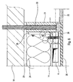
- La figure 1 représente une vue en coupe verticale d'un plafond sur lequel est installé un dispositif de chauffage conforme à un premier mode de réalisation de l'invention ;
- la figure 2 représente une vue de dessous du circuit de fluide caloporteur illustré sur la figue 1 ;
- la figure 3 représente schématiquement une vue en coupe verticale d'un plafond sur lequel est installé un dispositif de chauffage conforme à un deuxième mode de réalisation de l'invention ;
- la figure 4 représente une vue de dessus du réflecteur représenté sur la figure 1 ;
- la figure 5 représente schématiquement une vue de côté partielle d'une maison équipée d'un dispositif de chauffage illustré par la figure 3.
- la figure 6 représente une vue agrandie du dispositif de fixation du dispositif de chauffage illustré par la figue 3 ou 5.
- Figure 1 shows a vertical sectional view of a ceiling on which is installed a heating device according to a first embodiment of the invention;
- FIG. 2 represents a bottom view of the heat transfer fluid circuit illustrated in FIG. 1;
- Figure 3 schematically shows a vertical sectional view of a ceiling on which is installed a heating device according to a second embodiment of the invention;
- Figure 4 shows a top view of the reflector shown in Figure 1;
- FIG. 5 schematically represents a partial side view of a house equipped with a heating device illustrated by FIG. 3.
- FIG. 6 represents an enlarged view of the device for fixing the heating device illustrated by FIG. 3 or 5.
En référence aux figures 1, 2 et 4, le
dispositif de chauffage par le plafond selon l'invention
comporte un boítier 2 dans lequel sont agencés de façon
concentrique et dans un même plan parallèle au plafond,
une pluralité de conduits 4 destinés à constituer un
circuit pour la circulation d'un fluide caloporteur.
Chaque conduit 4 est relié d'une part à un collecteur
d'arrivée 6 par lequel le fluide caloporteur est
introduit simultanément dans les conduits 4, et d'autre
part à un collecteur de sortie 8 du fluide caloporteur
par lequel le fluide caloporteur, refroidi du fait de
son passage dans les conduits 4, est extrait
simultanément des conduits 4. Ces deux collecteurs sont
de préférence disposés à proximité l'un de l'autre.With reference to Figures 1, 2 and 4, the
ceiling heating device according to the invention
has a
Avantageusement, le dispositif de chauffage
comprend dix conduits concentriques regroupés en deux
ensembles de cinq conduits, chaque ensemble comportant
ses propres collecteurs d'arrivée 6 et de sortie 8.
Cette disposition permet d'obtenir une meilleure
répartition du débit de fluide caloporteur dans les
différents conduits 4.Advantageously, the heating device
includes ten concentric conduits grouped in two
sets of five conduits, each set comprising
its
Ce circuit de circulation de fluide caloporteur
est agencé dans un boítier 2 fermé, fixé au plafond 10
du local à chauffer, ce boítier comprenant un réflecteur
14 agencé au-dessus et à distance des conduits 4, et une
plaque inférieure 20 en un matériau rigide, résistant à
la température et à faible coefficient de dilatation,
fixée à distance en dessous des conduits 4. La présence
de lames d'air tout autour des conduits 4 permet à la
chaleur transportée par le fluide caloporteur de se
diffuser à l'intérieur du boítier, à la fois par
rayonnement et réflexion sur le réflecteur 14, par
conduction entre les conduits et l'air situé tout autour
dans le boítier, et par convection, l'air à l'intérieur
du boítier subissant un mouvement de convection. Il en
résulte à la fois une transmission efficace de la
chaleur entre le fluide caloporteur et l'air à
l'intérieur du boítier, et une répartition très homogène
de la température à l'intérieur du boítier et donc de la
plaque inférieure 20 qui est chauffée à la fois par
rayonnement et par contact avec l'air chaud à
l'intérieur du boítier. La plaque 20 transmet à son tour
la chaleur qu'elle reçoit à l'air du local à chauffer à
la fois par rayonnement et par conduction, ce qui permet
d'obtenir une transmission efficace de la chaleur à
l'air de la pièce.This heat transfer fluid circulation circuit
is arranged in a closed
L'épaisseur des lames d'air entre les conduits 4
et le réflecteur 14 ou la plaque inférieure 20 est de
préférence de l'ordre de 9 mm, ce qui permet d'éviter
tout risque de contact des conduits avec la plaque
inférieure 20 ou le réflecteur 14, en cas de dilatation
des conduits, et ce sans affecter la conduction de la
chaleur entre les conduits et la plaque.The thickness of the air gaps between the
Avantageusement, la surface occupée par les
conduits 4 représente environ 50% de la surface totale
du plafond 10, ce qui permet également d'obtenir une
répartition homogène de la température dans la pièce.Advantageously, the surface occupied by the
Dans un premier mode de réalisation illustré par
la figure 1, adapté au chauffage de locaux industriels,
le réflecteur 14 est constitué d'une seule pièce
enveloppant par le dessus et latéralement le circuit de
fluide caloporteur. Avantageusement, le réflecteur 14
comprend une partie centrale 20a abaissée par rapport à
la partie située au-dessus des conduits 4 de manière à
envelopper latéralement le conduit 4a situé le plus à
l'intérieur du circuit.In a first embodiment illustrated by
FIG. 1, suitable for heating industrial premises,
the
Les figures 3, 5 et 6 illustrent un deuxième
mode de réalisation adapté au chauffage de locaux
domestiques d'habitation, appartement ou maison
individuelle. Dans ce mode de réalisation, le boítier 2
est complètement fermé par une plaque supérieure 23
plaquée contre le plafond de la pièce à chauffer, une
plaque inférieure 20 en un matériau résistant à la
température et à faible coefficient de dilatation, et
des parois latérales 21. Il renferme un réflecteur
supérieur 14 plan muni de rebords latéraux, et un
circuit de fluide caloporteur constitué de conduits
4concentriques. Le boítier est fixé au plafond de la
pièce à chauffer par exemple par des vis de fixation 22
passant au travers des parois latérales 21, comme cela
est représenté plus en détail sur la figure 6.Figures 3, 5 and 6 illustrate a second
embodiment suitable for space heating
domestic servants, apartment or house
individual. In this embodiment, the
Par ailleurs, afin de limiter les déperditions
de chaleur vers le haut, un matériau 24 d'isolation
thermique est agencé dans le boítier entre le réflecteur
14 et la plaque 23. Alternativement, en remplacement du
réflecteur 14, le matériau 24 peut être muni sur sa face
inférieure d'une face réfléchissante, la plaque
supérieure 23 sur laquelle est fixé le matériau
d'isolation permettant de maintenir celui-ci, et donc sa
face réfléchissante, sensiblement horizontal.In addition, in order to limit losses
heat up,
Comme on peut le voir sur la figure 2, les
conduits 4 décrivent des rectangles concentriques. Bien
entendu la forme desdits conduits peut être adaptée à la
forme du plafond du local à chauffer de manière à
optimiser le rayonnement. Elle peut par exemple être
circulaire. Les conduits 4 sont fixés par des
entretoises 26 sur les parois latérales 21 par des
équerres 28 (voir figure 6). La section droite des
conduits est de préférence sensiblement rectangulaire,
de manière à limiter l'épaisseur du dispositif de
chauffage sans réduire le débit de fluide caloporteur
dans les conduits 4.As can be seen in Figure 2, the
La surface du faux plafond, constituée à 50 %
par la plaque inférieure 20, peut être complétée par des
plaques 25 telles que des plaques de placoplâtre.The surface of the false ceiling, made up to 50%
by the
De préférence, le fluide caloporteur est
constitué par de l'huile minérale ou de synthèse. Par
rapport à l'eau, plus couramment utilisée comme fluide
caloporteur, l'huile présente l'avantage de chauffer
trois fois moins vite, mais en contrepartie de refroidir
trois moins vite (transmission de la chaleur au milieu
ambiant plus rapide), de pouvoir être portée à des
températures beaucoup plus élevées, et de ne pas
attaquer par corrosion les conduits dans lesquels elle
circule. En outre, l'huile ne gèle et donc ne risque pas
de faire éclater les conduits 4 en cas d'arrêt du
dispositif de chauffage pendant l'hiver.Preferably, the heat transfer fluid is
consisting of mineral or synthetic oil. Through
compared to water, most commonly used as a fluid
oil has the advantage of heating
three times slower, but in return to cool
three slower (heat transfer in the middle
faster), to be able to be brought to
much higher temperatures, and not
corrosion attack the conduits in which it
circulates. In addition, the oil does not freeze and therefore does not risk
burst the
La plaque inférieure 20 destinée à fermer le
boítier 2 est constituée par exemple d'une plaque
d'éternit cellulose ou de kaolin, et le matériau 22
d'isolation thermique est constitué par de la laine de
verre ou de roche.The
La température de la pièce peut être réglée par
une simple commande du débit de fluide caloporteur dans
le circuit, par exemple au moyen d'une vanne (non
représentée) à débit variable, disposée en amont du
collecteur d'arrivée 6. The room temperature can be adjusted by
a simple control of the heat transfer fluid flow in
the circuit, for example by means of a valve (not
shown) with variable flow, arranged upstream of the
Le dispositif de chauffage selon l'invention permet de :
- homogénéiser la température dans le local à chauffer ;
- gérer automatiquement la température pièce par pièce ;
- supprimer les traces disgracieuses autour des corps de chauffe, générées par la carbonisation des poussières ;
- libérer l'espace dans les pièces et faciliter leur aménagement par l'élimination de tout corps de chauffe apparent ;
- s'adapter à la hauteur des pièces en cas d'installation dans une maison existante ;
- remplacer les épingles à gaz et les poêles à mazout dans les locaux industriels.
- homogenize the temperature in the room to be heated;
- automatically manage the temperature room by room;
- remove unsightly traces around the heating bodies, generated by the carbonization of dust;
- free up space in the rooms and facilitate their layout by eliminating any apparent heating element;
- adapt to the height of the rooms when installing in an existing house;
- replace gas pins and oil stoves in industrial premises.
Claims (9)
Applications Claiming Priority (2)
| Application Number | Priority Date | Filing Date | Title |
|---|---|---|---|
| FR9914001 | 1999-11-08 | ||
| FR9914001A FR2800852B1 (en) | 1999-11-08 | 1999-11-08 | CEILING HEATING DEVICE |
Publications (2)
| Publication Number | Publication Date |
|---|---|
| EP1098143A1 true EP1098143A1 (en) | 2001-05-09 |
| EP1098143B1 EP1098143B1 (en) | 2003-08-13 |
Family
ID=9551855
Family Applications (1)
| Application Number | Title | Priority Date | Filing Date |
|---|---|---|---|
| EP00403046A Expired - Lifetime EP1098143B1 (en) | 1999-11-08 | 2000-11-02 | Heating ceiling |
Country Status (4)
| Country | Link |
|---|---|
| EP (1) | EP1098143B1 (en) |
| AT (1) | ATE247258T1 (en) |
| DE (1) | DE60004460D1 (en) |
| FR (1) | FR2800852B1 (en) |
Cited By (2)
| Publication number | Priority date | Publication date | Assignee | Title |
|---|---|---|---|---|
| EP1243861A2 (en) * | 2001-03-23 | 2002-09-25 | Supellex AG | Construction of a heat exchanger |
| CN109059081A (en) * | 2018-06-25 | 2018-12-21 | 中国矿业大学 | A kind of ceiling mounting type indoor heating device |
Citations (5)
| Publication number | Priority date | Publication date | Assignee | Title |
|---|---|---|---|---|
| GB778805A (en) * | 1953-11-10 | 1957-07-10 | Henry Hope Bruce | Improvements in apparatus for heating buildings |
| DE974794C (en) * | 1949-03-10 | 1961-05-04 | Felix Andre Missenard | Radiant heating system with a heat-reflecting screen over the heating surfaces |
| US3741478A (en) * | 1971-07-09 | 1973-06-26 | F Summa | Heating coils |
| DE8400402U1 (en) * | 1984-01-09 | 1991-08-22 | Weber, Manfred Peter | Sandwich heat exchanger |
| EP0511645A1 (en) * | 1991-04-29 | 1992-11-04 | Lindner Ag | Wall or ceiling covering with a heating or cooling installation |
Family Cites Families (1)
| Publication number | Priority date | Publication date | Assignee | Title |
|---|---|---|---|---|
| US4164933A (en) | 1976-10-06 | 1979-08-21 | Alosi Anthony C | Concrete solar collectors |
-
1999
- 1999-11-08 FR FR9914001A patent/FR2800852B1/en not_active Expired - Fee Related
-
2000
- 2000-11-02 AT AT00403046T patent/ATE247258T1/en not_active IP Right Cessation
- 2000-11-02 EP EP00403046A patent/EP1098143B1/en not_active Expired - Lifetime
- 2000-11-02 DE DE60004460T patent/DE60004460D1/en not_active Expired - Lifetime
Patent Citations (5)
| Publication number | Priority date | Publication date | Assignee | Title |
|---|---|---|---|---|
| DE974794C (en) * | 1949-03-10 | 1961-05-04 | Felix Andre Missenard | Radiant heating system with a heat-reflecting screen over the heating surfaces |
| GB778805A (en) * | 1953-11-10 | 1957-07-10 | Henry Hope Bruce | Improvements in apparatus for heating buildings |
| US3741478A (en) * | 1971-07-09 | 1973-06-26 | F Summa | Heating coils |
| DE8400402U1 (en) * | 1984-01-09 | 1991-08-22 | Weber, Manfred Peter | Sandwich heat exchanger |
| EP0511645A1 (en) * | 1991-04-29 | 1992-11-04 | Lindner Ag | Wall or ceiling covering with a heating or cooling installation |
Cited By (3)
| Publication number | Priority date | Publication date | Assignee | Title |
|---|---|---|---|---|
| EP1243861A2 (en) * | 2001-03-23 | 2002-09-25 | Supellex AG | Construction of a heat exchanger |
| EP1243861A3 (en) * | 2001-03-23 | 2003-06-11 | Supellex AG | Construction of a heat exchanger |
| CN109059081A (en) * | 2018-06-25 | 2018-12-21 | 中国矿业大学 | A kind of ceiling mounting type indoor heating device |
Also Published As
| Publication number | Publication date |
|---|---|
| ATE247258T1 (en) | 2003-08-15 |
| DE60004460D1 (en) | 2003-09-18 |
| FR2800852A1 (en) | 2001-05-11 |
| EP1098143B1 (en) | 2003-08-13 |
| FR2800852B1 (en) | 2001-12-21 |
Similar Documents
| Publication | Publication Date | Title |
|---|---|---|
| EP2446197B1 (en) | Reversible radiator | |
| US20030047181A1 (en) | Solar collector pipe | |
| FR2723631A3 (en) | APPARATUS FOR HEATING SPACES | |
| EP1098143B1 (en) | Heating ceiling | |
| EP4139611B1 (en) | Climate control panel | |
| EP1695010A1 (en) | Heating and air-conditioning device | |
| EP2405209A1 (en) | Air-intake and mixing device for a heat pump | |
| EP0814305B1 (en) | Modular panel for air conditioning | |
| FR2482707A1 (en) | HEATING SYSTEM | |
| FR3048489B1 (en) | VENTILATION SYSTEM OF A BUILDING | |
| FR2510728A1 (en) | METHOD AND INSTALLATION OF AIR CONDITIONING FOR INDUSTRIAL PREMISES | |
| FR3129712A1 (en) | Device emitting heat or cold with forced convection and heating or cooling system incorporating this device | |
| FR2481422A1 (en) | PROCESS AND INSTALLATION FOR THE PRODUCTION AND DISTRIBUTION OF HEAT INSIDE THE PREMISES OF A BUILDING | |
| EP1121562B1 (en) | Heating door | |
| BE1014988A7 (en) | Protective shelter for fire has metal wall panel with secondary inner panel defining flow channels for coolant flow | |
| FR2459948A1 (en) | Solar water heater with pyramidal reservoir - has convection currents established under influence of solar radiation causing hottest water to collect at apex (PT 12.12.80) | |
| FR2976054A1 (en) | RECEIVER FOR SOLAR POWER PLANT WITH EXTENDED LIFE | |
| FR2633380A1 (en) | Device for air-conditioning premises using heat energy exchange by low-temperature infrared radiation | |
| FR2459438A1 (en) | HEAT EXCHANGER FOR HOT WATER HEATING SYSTEMS | |
| FR2602856A1 (en) | ARRANGEMENT FOR LOWERING THE TEMPERATURE OF THE SIDE WALLS OF A COOKER | |
| FR3104242A1 (en) | Solar thermal collector, solar thermal panel and method of heating a building with integrated heat storage. | |
| FR2678356A1 (en) | Catalytic burner with air sucked in | |
| EP4127569A1 (en) | Heating/cooling walls and ceilings | |
| FR2898963A1 (en) | Universal accessory for optimizing yield of fluid radiator, has resistor placed in collector connected in symmetry with upper and lower ends along heating body, and control unit controlling resistor and circulation of heat transfer fluid | |
| BE626483A (en) |
Legal Events
| Date | Code | Title | Description |
|---|---|---|---|
| PUAI | Public reference made under article 153(3) epc to a published international application that has entered the european phase |
Free format text: ORIGINAL CODE: 0009012 |
|
| AK | Designated contracting states |
Kind code of ref document: A1 Designated state(s): AT BE CH CY DE DK ES FI FR GB GR IE IT LI LU MC NL PT SE TR |
|
| AX | Request for extension of the european patent |
Free format text: AL;LT;LV;MK;RO;SI |
|
| 17P | Request for examination filed |
Effective date: 20011109 |
|
| AKX | Designation fees paid |
Free format text: AT BE CH CY DE DK ES FI FR GB GR IE IT LI LU MC NL PT SE TR |
|
| 17Q | First examination report despatched |
Effective date: 20020206 |
|
| GRAH | Despatch of communication of intention to grant a patent |
Free format text: ORIGINAL CODE: EPIDOS IGRA |
|
| GRAH | Despatch of communication of intention to grant a patent |
Free format text: ORIGINAL CODE: EPIDOS IGRA |
|
| GRAA | (expected) grant |
Free format text: ORIGINAL CODE: 0009210 |
|
| AK | Designated contracting states |
Designated state(s): AT BE CH CY DE DK ES FI FR GB GR IE IT LI LU MC NL PT SE TR |
|
| PG25 | Lapsed in a contracting state [announced via postgrant information from national office to epo] |
Ref country code: IT Free format text: LAPSE BECAUSE OF FAILURE TO SUBMIT A TRANSLATION OF THE DESCRIPTION OR TO PAY THE FEE WITHIN THE PRESCRIBED TIME-LIMIT;WARNING: LAPSES OF ITALIAN PATENTS WITH EFFECTIVE DATE BEFORE 2007 MAY HAVE OCCURRED AT ANY TIME BEFORE 2007. THE CORRECT EFFECTIVE DATE MAY BE DIFFERENT FROM THE ONE RECORDED. Effective date: 20030813 Ref country code: NL Free format text: LAPSE BECAUSE OF FAILURE TO SUBMIT A TRANSLATION OF THE DESCRIPTION OR TO PAY THE FEE WITHIN THE PRESCRIBED TIME-LIMIT Effective date: 20030813 Ref country code: ES Free format text: LAPSE BECAUSE OF FAILURE TO SUBMIT A TRANSLATION OF THE DESCRIPTION OR TO PAY THE FEE WITHIN THE PRESCRIBED TIME-LIMIT Effective date: 20030813 Ref country code: IE Free format text: LAPSE BECAUSE OF FAILURE TO SUBMIT A TRANSLATION OF THE DESCRIPTION OR TO PAY THE FEE WITHIN THE PRESCRIBED TIME-LIMIT Effective date: 20030813 Ref country code: FI Free format text: LAPSE BECAUSE OF FAILURE TO SUBMIT A TRANSLATION OF THE DESCRIPTION OR TO PAY THE FEE WITHIN THE PRESCRIBED TIME-LIMIT Effective date: 20030813 Ref country code: AT Free format text: LAPSE BECAUSE OF FAILURE TO SUBMIT A TRANSLATION OF THE DESCRIPTION OR TO PAY THE FEE WITHIN THE PRESCRIBED TIME-LIMIT Effective date: 20030813 Ref country code: GB Free format text: LAPSE BECAUSE OF FAILURE TO SUBMIT A TRANSLATION OF THE DESCRIPTION OR TO PAY THE FEE WITHIN THE PRESCRIBED TIME-LIMIT Effective date: 20030813 Ref country code: TR Free format text: LAPSE BECAUSE OF FAILURE TO SUBMIT A TRANSLATION OF THE DESCRIPTION OR TO PAY THE FEE WITHIN THE PRESCRIBED TIME-LIMIT Effective date: 20030813 |
|
| REG | Reference to a national code |
Ref country code: GB Ref legal event code: FG4D Free format text: NOT ENGLISH |
|
| REG | Reference to a national code |
Ref country code: CH Ref legal event code: EP |
|
| REG | Reference to a national code |
Ref country code: IE Ref legal event code: FG4D Free format text: FRENCH |
|
| REF | Corresponds to: |
Ref document number: 60004460 Country of ref document: DE Date of ref document: 20030918 Kind code of ref document: P |
|
| PG25 | Lapsed in a contracting state [announced via postgrant information from national office to epo] |
Ref country code: CY Free format text: LAPSE BECAUSE OF FAILURE TO SUBMIT A TRANSLATION OF THE DESCRIPTION OR TO PAY THE FEE WITHIN THE PRESCRIBED TIME-LIMIT Effective date: 20031102 Ref country code: LU Free format text: LAPSE BECAUSE OF NON-PAYMENT OF DUE FEES Effective date: 20031102 |
|
| PG25 | Lapsed in a contracting state [announced via postgrant information from national office to epo] |
Ref country code: SE Free format text: LAPSE BECAUSE OF FAILURE TO SUBMIT A TRANSLATION OF THE DESCRIPTION OR TO PAY THE FEE WITHIN THE PRESCRIBED TIME-LIMIT Effective date: 20031113 Ref country code: DK Free format text: LAPSE BECAUSE OF FAILURE TO SUBMIT A TRANSLATION OF THE DESCRIPTION OR TO PAY THE FEE WITHIN THE PRESCRIBED TIME-LIMIT Effective date: 20031113 Ref country code: GR Free format text: LAPSE BECAUSE OF FAILURE TO SUBMIT A TRANSLATION OF THE DESCRIPTION OR TO PAY THE FEE WITHIN THE PRESCRIBED TIME-LIMIT Effective date: 20031113 |
|
| PG25 | Lapsed in a contracting state [announced via postgrant information from national office to epo] |
Ref country code: DE Free format text: LAPSE BECAUSE OF FAILURE TO SUBMIT A TRANSLATION OF THE DESCRIPTION OR TO PAY THE FEE WITHIN THE PRESCRIBED TIME-LIMIT Effective date: 20031114 |
|
| PG25 | Lapsed in a contracting state [announced via postgrant information from national office to epo] |
Ref country code: BE Free format text: LAPSE BECAUSE OF NON-PAYMENT OF DUE FEES Effective date: 20031130 Ref country code: MC Free format text: LAPSE BECAUSE OF NON-PAYMENT OF DUE FEES Effective date: 20031130 |
|
| PG25 | Lapsed in a contracting state [announced via postgrant information from national office to epo] |
Ref country code: PT Free format text: LAPSE BECAUSE OF FAILURE TO SUBMIT A TRANSLATION OF THE DESCRIPTION OR TO PAY THE FEE WITHIN THE PRESCRIBED TIME-LIMIT Effective date: 20040113 |
|
| NLV1 | Nl: lapsed or annulled due to failure to fulfill the requirements of art. 29p and 29m of the patents act | ||
| GBV | Gb: ep patent (uk) treated as always having been void in accordance with gb section 77(7)/1977 [no translation filed] |
Effective date: 20030813 |
|
| REG | Reference to a national code |
Ref country code: IE Ref legal event code: FD4D |
|
| BERE | Be: lapsed |
Owner name: *SAINSILY PIERRE-EDOUARD Effective date: 20031130 |
|
| PLBE | No opposition filed within time limit |
Free format text: ORIGINAL CODE: 0009261 |
|
| STAA | Information on the status of an ep patent application or granted ep patent |
Free format text: STATUS: NO OPPOSITION FILED WITHIN TIME LIMIT |
|
| PG25 | Lapsed in a contracting state [announced via postgrant information from national office to epo] |
Ref country code: FR Free format text: LAPSE BECAUSE OF NON-PAYMENT OF DUE FEES Effective date: 20040730 |
|
| 26N | No opposition filed |
Effective date: 20040514 |
|
| REG | Reference to a national code |
Ref country code: FR Ref legal event code: ST |
|
| PG25 | Lapsed in a contracting state [announced via postgrant information from national office to epo] |
Ref country code: LI Free format text: LAPSE BECAUSE OF NON-PAYMENT OF DUE FEES Effective date: 20041130 Ref country code: CH Free format text: LAPSE BECAUSE OF NON-PAYMENT OF DUE FEES Effective date: 20041130 |
|
| REG | Reference to a national code |
Ref country code: CH Ref legal event code: PL |