EP1098082A2 - Kolben - Google Patents
Kolben Download PDFInfo
- Publication number
- EP1098082A2 EP1098082A2 EP00123700A EP00123700A EP1098082A2 EP 1098082 A2 EP1098082 A2 EP 1098082A2 EP 00123700 A EP00123700 A EP 00123700A EP 00123700 A EP00123700 A EP 00123700A EP 1098082 A2 EP1098082 A2 EP 1098082A2
- Authority
- EP
- European Patent Office
- Prior art keywords
- piston
- cooling
- outer cooling
- recesses
- recess
- Prior art date
- Legal status (The legal status is an assumption and is not a legal conclusion. Google has not performed a legal analysis and makes no representation as to the accuracy of the status listed.)
- Granted
Links
- 238000001816 cooling Methods 0.000 claims abstract description 87
- 238000002485 combustion reaction Methods 0.000 claims abstract description 12
- 230000002093 peripheral effect Effects 0.000 claims description 7
- 239000002184 metal Substances 0.000 claims 1
- 238000004519 manufacturing process Methods 0.000 abstract description 4
- 238000000034 method Methods 0.000 abstract description 3
- 230000000694 effects Effects 0.000 abstract description 2
- 238000003754 machining Methods 0.000 abstract description 2
- 238000003801 milling Methods 0.000 abstract description 2
- 239000002826 coolant Substances 0.000 description 7
- 238000013461 design Methods 0.000 description 4
- 238000012545 processing Methods 0.000 description 3
- 230000001154 acute effect Effects 0.000 description 1
- 238000013459 approach Methods 0.000 description 1
- 230000006835 compression Effects 0.000 description 1
- 238000007906 compression Methods 0.000 description 1
- 239000000110 cooling liquid Substances 0.000 description 1
- 230000001771 impaired effect Effects 0.000 description 1
- 239000003595 mist Substances 0.000 description 1
- 238000005192 partition Methods 0.000 description 1
- 238000004080 punching Methods 0.000 description 1
- 230000002787 reinforcement Effects 0.000 description 1
- 238000012549 training Methods 0.000 description 1
- 230000003313 weakening effect Effects 0.000 description 1
Images


Classifications
-
- F—MECHANICAL ENGINEERING; LIGHTING; HEATING; WEAPONS; BLASTING
- F02—COMBUSTION ENGINES; HOT-GAS OR COMBUSTION-PRODUCT ENGINE PLANTS
- F02F—CYLINDERS, PISTONS OR CASINGS, FOR COMBUSTION ENGINES; ARRANGEMENTS OF SEALINGS IN COMBUSTION ENGINES
- F02F3/00—Pistons
- F02F3/16—Pistons having cooling means
- F02F3/20—Pistons having cooling means the means being a fluid flowing through or along piston
- F02F3/22—Pistons having cooling means the means being a fluid flowing through or along piston the fluid being liquid
-
- F—MECHANICAL ENGINEERING; LIGHTING; HEATING; WEAPONS; BLASTING
- F02—COMBUSTION ENGINES; HOT-GAS OR COMBUSTION-PRODUCT ENGINE PLANTS
- F02B—INTERNAL-COMBUSTION PISTON ENGINES; COMBUSTION ENGINES IN GENERAL
- F02B23/00—Other engines characterised by special shape or construction of combustion chambers to improve operation
- F02B23/02—Other engines characterised by special shape or construction of combustion chambers to improve operation with compression ignition
- F02B23/06—Other engines characterised by special shape or construction of combustion chambers to improve operation with compression ignition the combustion space being arranged in working piston
- F02B23/0672—Omega-piston bowl, i.e. the combustion space having a central projection pointing towards the cylinder head and the surrounding wall being inclined towards the cylinder center axis
-
- F—MECHANICAL ENGINEERING; LIGHTING; HEATING; WEAPONS; BLASTING
- F02—COMBUSTION ENGINES; HOT-GAS OR COMBUSTION-PRODUCT ENGINE PLANTS
- F02F—CYLINDERS, PISTONS OR CASINGS, FOR COMBUSTION ENGINES; ARRANGEMENTS OF SEALINGS IN COMBUSTION ENGINES
- F02F3/00—Pistons
-
- Y—GENERAL TAGGING OF NEW TECHNOLOGICAL DEVELOPMENTS; GENERAL TAGGING OF CROSS-SECTIONAL TECHNOLOGIES SPANNING OVER SEVERAL SECTIONS OF THE IPC; TECHNICAL SUBJECTS COVERED BY FORMER USPC CROSS-REFERENCE ART COLLECTIONS [XRACs] AND DIGESTS
- Y02—TECHNOLOGIES OR APPLICATIONS FOR MITIGATION OR ADAPTATION AGAINST CLIMATE CHANGE
- Y02T—CLIMATE CHANGE MITIGATION TECHNOLOGIES RELATED TO TRANSPORTATION
- Y02T10/00—Road transport of goods or passengers
- Y02T10/10—Internal combustion engine [ICE] based vehicles
- Y02T10/12—Improving ICE efficiencies
Definitions
- the invention relates to a piston according to the preamble of Claim 1.
- a piston which is in the range of Overhang of the piston ring zone has a cavity that is perpendicular extends upwards. This recess is in relation to the outer surface of the Piston ring zone set back and should the piston weight Reduce. There is no connection to the inside of the piston.
- EP 0 167 976 A2 describes a piston with cylinder tube cooling known.
- an annular cooling space is provided, which on the Piston circumferential surface to the cylinder liner is open. It is about essentially an annular or tubular notch in the Piston peripheral surface, the cooling space over the entire circumference of the Piston is open to the cylinder liner.
- the refrigerator is in the further from two axial sections, of which the combustion chamber side as an annular groove is formed by the inner piston body and an outer Ring wall is formed, which is a boundary to the cylinder tube and the Piston rings carries.
- the cooling space extends up to in this axial section behind the piston rings.
- the other axial section is almost on his entire axial height to the cylinder tube and has four partitions on, radially from the inner wall of the cold room to the piston peripheral surface and axially from the connecting rod ends of the cooling space to the axial start the ring groove.
- This configuration of the cold room requires one complex processing.
- EP 0 855 499 A1 describes a liquid-cooled piston for Internal combustion engines known, the at least one in a piston upper part trained, seginent-shaped coolant channel, which with respect to Piston pin axis symmetrical locations for coolant supply and Has coolant drain openings. Furthermore, a radially extending, in its course to the crankcase is a closed connection channel provided that with the ring segment-shaped channels in the area of Openings is connected.
- Another version provides two cooler bags, which are separated by one Cut-out of the lower surface of the overhanging areas of the piston head available.
- a piston which is characterized in that that the outer cooling recesses have a conical shape, the outer cooling recesses inclined inward with respect to the piston axis are arranged and with increasing distance from the respective pin hub run towards the combustion chamber trough and that the outer cooling recesses in the Area between the shaft wall sections and the connecting walls in pass over an inner bucket recess that is open inwards and downwards.
- the oil can caught when lowering the piston and pushed up, so that the oil is brought very close to the piston crown. At the same time the oil is pressed into the internal cooling recesses.
- the Corresponding openings provided connecting walls that such are arranged so that the stability of the piston is not impaired.
- the oblique orientation of the outer cooling recesses can be easily Manufacture way by milling or punching processes.
- the tools are accordingly applied obliquely to the piston. It is therefore only one Processing step necessary, while in the prior art at Training appropriate cooling recesses several processing steps required are.
- the outer cooling recess preferably extends in the radial direction at least partially up to the piston peripheral surface of the piston skirt. It will at least partially become a relatively sharp edge at the top the outer cooling recess formed so that when lowering the piston Oil is captured even better. You get at the top of the outer one Cooling recess a kind of scraper edge that directs the oil inwards.
- the outer cooling recess preferably extends in the circumferential direction at least partially into the shaft wall sections that the Connecting walls are adjacent. This opens up a large opening Available to catch the oil when lowering the piston. The This further improves the cooling effect.
- the central inclination axis of the outer cooling recess preferably forms with the piston axis an angle ⁇ between 10 ° and 60 °. Here are small angles in the range from 10 ° to 20 ° are preferred. Under the middle The axis of inclination becomes the central axis between the inner and outer walls the outer cooling recess understood the shape of the cooling recess define.
- this is preferably delimited by inner and outer walls arranged in parallel.
- Other designs of the inner and outer walls are possible, one The inclination of the outer cooling recess is to be maintained.
- the outer cooling recess advantageously extends up to behind the ring grooves, so that the ring groove area is cooled accordingly becomes. It is particularly advantageous if the outer cooling recess extends up to extends behind the first ring groove or further up.
- Each inner cooling recess preferably connects both outer ones Cooling recesses so that a circumferential cooling channel is formed.
- the inner cooling recesses are preferably in the form of ring sections educated.
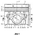
- Figure 1 is a piston with a piston ring zone 1, in the ring grooves 2a, b and c are arranged and shown with a piston shaft 10. Above and below the ring grooves 2a, bc, the piston ring zone 1 has a upper 16a and a lower piston peripheral surface 16b.
- the ring grooves 2b, c are used to hold the oil control rings or the ring groove 2a to hold them of the compression ring.
- the design of the ring grooves corresponds to that State of the art.
- the piston skirt 10 has two piston skirt sections 14a, b, which over Connecting walls 15a, b are connected to one another, these Connecting walls set back inwards in the direction of the piston axis are and have the pin bosses 11 with bearing eyes 12.
- the Connecting walls 15a, b are thus also opposite Shaft wall sections 14a, b set back radially.
- the outer Cooling recess is formed by an inner wall 23b and an outer wall 23a (see Figure 3a) limited, of which only the inner wall 23b can be seen in Figure 1. Because of the recessed connecting walls and the extension of the outer cooling recesses in the shaft wall sections 14a, b is the Inner wall pulled down laterally next to the bearing eye 12, see above that lateral sections 24a, b are formed.
- the upper edge 26 of the outer cooling recess 20 runs parallel to the Ring grooves 2a, b and c.
- the lower edge sections 27a and b also run parallel to the upper edge 26 and are over the central edge portion 27c connected to each other, which runs in a circular arc around the bearing eye 12.
- the two lateral edges 28a, b are slightly curved and are located in the respective shaft wall section 14a, b. Because the outer cooling recess 20 into the region of the shaft wall sections 14a, b extends, there is a large opening for receiving the oil to be collected.
- the connecting walls 15a, b extend down as far as that Shaft wall sections 14a and b. Both the shaft wall sections 14a and b as well as the connecting walls 15a and b have at the lower end Stiffening ribs 30 that increase stability.
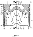
- FIG. 2 is a vertical section through that shown in FIG. 1 Pistons shown.
- the breakthroughs 25 shown in the figure 1 are only hinted at, and which are the connection of the outer Make cooling recesses 20 to the interior of the piston are in the upper Area of the connecting walls 14a, b arranged so that the associated Weakening of the wall 15a, b does not weaken the entire piston leads.
- the openings 25 are arranged in the vicinity of the area where the inner cooling recess 21 is arranged. This is after inside and below open cooling recesses, which are designed as ring sections and are arranged on the underside of the piston crown 4.
- the inner ones Cooling recesses 21 extend upwards behind the ring grooves 2a, b, c and extend approximately to the area of the central annular groove 2b.
- the cooling oil that through the openings 25 of the outer cooling recess 20th enters the inside is also in the vicinity of the ring grooves 2b and 2c headed. At the same time, when the piston is lowered, the piston in its Oil mist located inside and caught in the interior Cooling recesses 21 collected. It is also possible that the oil through the Openings 25 is flushed into the outer cooling recesses 20. Thereby, that an unimpeded exchange of the cooling oil from the inner Cooling recesses 21 to the outer cooling recesses 20 and vice versa optimal cooling is ensured.
- FIG. 3a shows a section along the line III-III of the in FIG. 2nd shown piston shown. It can clearly be seen that the Connecting wall 15a is offset inwards with respect to piston ring zone 1, so that the overhang of the piston ring zone 1 for the cooling recess 20 Available. The direction of flow of the oil is through the arrow characterized, it is also possible that the oil from the inside out can flow.
- the central axis of inclination 22 of the outer cooling recess 20 forms with the Piston axis 5 an angle ⁇ , which in the illustration shown here at approx. 40 °.
- the orientation and inclination of the outer cooling recess 20 is chosen so that the outer cooling recess on the combustion chamber trough 3 approaches.
- the outer cooling recess 20 also extends into the area the middle ring groove 2b.
- the outer extends in the radial direction Cooling recess 20 so far that the upper edge 26 of the outer cooling recess 20 on the lower piston peripheral surface 16b located.
- the outer wall 23a forms one with the piston peripheral surface 16b acute angle, which forms a kind of scraper edge.
- In the camp eye 12 is an annular groove 17 for a stop ring in the outer edge region of the bolt.
- FIG. 3b shows a further embodiment of the outer one Cooling recess 20 is shown, in which the inner and outer walls 23a, 23b are not arranged parallel to each other but in the direction Combustion chamber trough 3 converge.
- the central axis of inclination 22 will through the central axis between the inner wall 23b and the outer wall 23a the outer cooling recess 20 defined.
- FIG. 3c 20 A further embodiment of the outer cooling recess is shown in FIG. 3c 20 shown.
- the inner wall 23b goes into an upper area Inner wall portion 23b 'about, which is substantially vertical.
- the Outer wall 23a merges into an upper outer wall section 23a ', which is also arranged almost vertically.
- the outer Cooling recess 20 becomes the central axis of inclination 22 through the two Defined inner and outer walls 23a, 23b, which in turn the shape of the Define outer cooling recess 20.
- FIG. 4 is a section along the line IV-IV through the one in FIG. 1 shown pistons.
- the thickness of the shaft wall sections 14a, b is significantly less than that of the connecting walls 15a, b.
- the wall thickness is approx. 3 to 4 times larger than that of the shaft wall sections, which increases the stability of the entire piston is significantly increased.
Landscapes
- Engineering & Computer Science (AREA)
- Chemical & Material Sciences (AREA)
- Combustion & Propulsion (AREA)
- Mechanical Engineering (AREA)
- General Engineering & Computer Science (AREA)
- Physics & Mathematics (AREA)
- Fluid Mechanics (AREA)
- Pistons, Piston Rings, And Cylinders (AREA)
Abstract
Description
- Figur 1
- eine Seitenansicht eines Kolbens,
- Figur 2
- einen Vertikalschnitt durch den in Figur 1 gezeigten Kolben,
- Figur 3a
- einen Schnitt längs der Linie III-III durch den in Figur 2 gezeigten Kolben,
- Figur 3b,c
- Schnitte gemäß weiterer Ausführungsformen, und
- Figur 4
- einen Schnitt längs der Linie IV-IV des in Figur 1 gezeigten Kolbens.
- 1
- Kolbenringzone
- 2a,b,c
- Ringnut
- 3
- Brennraummulde
- 4
- Kolbenboden
- 5
- Kolbenachse
- 6
- Kolbenoberseite
- 10
- Kolbenschaft
- 11
- Bolzennabe
- 12
- Lagerauge
- 13
- Bolzenachse
- 14a,b
- Schaftwandabschnitt
- 15a,b
- Verbindungswand
- 16a
- oberer Wandabschnitt
- 16b
- unterer Wandabschnitt
- 11
- Ringnut für Anschlagring
- 20
- äußere Kühlausnehmung
- 21
- innere Kühlausnehmung
- 22
- Neigungsachse
- 23a
- Außenwand
- 23a'
- oberer Außenwandabschnitt
- 23b
- Innenwand
- 23b'
- oberer Innenwandabschnitt
- 24a,b
- seitlicher Abschnitt
- 25
- Durchbruch
- 26
- oberer Rand
- 27a,b,c,
- unterer Randabschnitt
- 28a,b
- seitlicher Rand
- 30
- Verstärkungsrippe
Claims (9)
- Kolben, insbesondere aus Leichtmetall, mit einer Kolbenringzone (1), die am Außenumfang Kolbenringnuten (2a,b,c) und an der Oberseite (6) eine Brennraummulde (3) aufweist, und mit einem Kolbenschaft (10), der zwei Schaftwandabschnitte (14a,b) sowie zwei die Schaftwandabschnitte (14a,b) verbindende Verbindungswände (15a,b) aufweist, die in Richtung Kolbenachse (5) zurückversetzt angeordnet sind, zwei Lageraugen (12) tragende Bolzennaben (11) aufweisen und sich bis zum unteren Rand des Kolbenschafts (10) erstrecken, wobei die Kolbenringzone (1) im Bereich der zurückgesetzten Verbindungswände (15a,b) jeweils eine nach unten offene Kühlausnehmung aufweisen, dadurch gekennzeichnet,daß die äußere Kühlausnehmungen (20) eine konische Gestalt aufweisen, wobei die äußere Kühlausnehmungen (20) bezüglich der Kolbenachse (5) einwärts geneigt angeordnet sind und mit zunehmendem Abstand von der jeweiligen Bolzennabe (11) auf die Brennraummulde (3) zulaufen, unddaß die äußeren Kühlausnehmungen (20) im Bereich zwischen den Schaftwandabschnitten (14a,b) jeweils in eine nach innen und unten offene innere Kühlausnehmung (21) übergehen.
- Kolben nach Anspruch 1, dadurch gekennzeichnet, daß die äußere Kühlausnehmung (20) sich in radialer Richtung mindestens teilweise bis an die Kolbenumfangsfläche (16b) des Kolbenschaftes (10) erstreckt.
- Kolben nach Anspruch 1 oder 2, dadurch gekennzeichnet, daß sich die äußere Kühlausnehmung (20) in Umfangsrichtung mindestens teilweise bis in die Schaftwandabschnitte (14a,b) erstreckt.
- Kolben nach Ansprüche 1 bis 3, dadurch gekennzeichnet, daß die Innenwand (23b) er äußeren Kühlausnehmung (20) seitlich des jeweiligen Lagerauges (12) zwei nach unten gezogene Abschnitte (24a, b) aufweist.
- Kolben nach einem der Ansprüche 1 bis 4, dadurch gekennzeichnet, daß die mittlere Neigungsachse (22) der äußeren Kühlausnehmung (20) mit der Kolbenachse (5) einen Winkel α zwischen 10° und 60° bilden.
- Kolben nach einem der Ansprüche 1 bis 5, dadurch gekennzeichnet, daß die äußere Kühlausnehmung (20) durch parallel angeordnete Innen- und Außenwänd (23a, 23b) begrenzt ist.
- Kolben nach einem der Ansprüche 1 bis 6, dadurch gekennzeichnet, daß sich die äußere Kühlausnehmung (20) nach oben bis hinter die Ringnuten (2a-c) erstreckt.
- Kolben nach einem der Ansprüche 1 bis 7, dadurch gekennzeichnet, daß jede innere Kühlausnehmung (21) beide äußeren Kühlausnehmungen (20) verbindet.
- Kolben nach einem der Ansprüche 1 bis 8, dadurch gekennzeichnet, daß die inneren Kühlausnehmungen (21) als Ringabschnitte ausgebildet sind.
Applications Claiming Priority (2)
| Application Number | Priority Date | Filing Date | Title |
|---|---|---|---|
| DE19953384 | 1999-11-06 | ||
| DE19953384A DE19953384C1 (de) | 1999-11-06 | 1999-11-06 | Kolben |
Publications (3)
| Publication Number | Publication Date |
|---|---|
| EP1098082A2 true EP1098082A2 (de) | 2001-05-09 |
| EP1098082A3 EP1098082A3 (de) | 2002-02-13 |
| EP1098082B1 EP1098082B1 (de) | 2005-06-29 |
Family
ID=7928086
Family Applications (1)
| Application Number | Title | Priority Date | Filing Date |
|---|---|---|---|
| EP00123700A Expired - Lifetime EP1098082B1 (de) | 1999-11-06 | 2000-10-31 | Kolben |
Country Status (2)
| Country | Link |
|---|---|
| EP (1) | EP1098082B1 (de) |
| DE (2) | DE19953384C1 (de) |
Cited By (1)
| Publication number | Priority date | Publication date | Assignee | Title |
|---|---|---|---|---|
| WO2015124748A1 (de) * | 2014-02-21 | 2015-08-27 | Ks Kolbenschmidt Gmbh | Kolben ohne geschlossenen kühlraum für verbrennungsmotoren mit mindestens einer kühlöldüse pro zylinder sowie ein verfahren zur kühlung dieses kolbens |
Families Citing this family (1)
| Publication number | Priority date | Publication date | Assignee | Title |
|---|---|---|---|---|
| DE10311155A1 (de) * | 2003-03-14 | 2004-09-23 | Gapi Technische Produkte Gmbh | Dichtring und Dichtringanordnung |
Citations (4)
| Publication number | Priority date | Publication date | Assignee | Title |
|---|---|---|---|---|
| EP0167376A2 (de) | 1984-07-02 | 1986-01-08 | Hercules Incorporated | Carbonatderivate des Ananasketons |
| EP0838587A1 (de) | 1996-10-23 | 1998-04-29 | Alcan Deutschland Gmbh | Leichtbaukolben |
| EP0855499A1 (de) | 1997-01-28 | 1998-07-29 | Alcan Deutschland Gmbh | Flüssigkeitsgekühlter Kolben |
| DE19747746C1 (de) | 1997-10-29 | 1998-11-19 | Alcan Gmbh | Gekühlter Kolben für Verbrennungskraftmaschinen und Verbrennungskraftmaschinen mit derartigen Kolben |
Family Cites Families (3)
| Publication number | Priority date | Publication date | Assignee | Title |
|---|---|---|---|---|
| DE3425228A1 (de) * | 1984-07-09 | 1986-02-06 | Klöckner-Humboldt-Deutz AG, 5000 Köln | Zylinderrohrkuehlung |
| DE4210056A1 (de) * | 1992-03-27 | 1993-09-30 | Mahle Gmbh | Hubkolben eines Verbrennungsmotors |
| DE19522756A1 (de) * | 1995-06-27 | 1997-01-02 | Kolbenschmidt Ag | Tauchkolben für Brennkraftmaschinen |
-
1999
- 1999-11-06 DE DE19953384A patent/DE19953384C1/de not_active Expired - Lifetime
-
2000
- 2000-10-31 DE DE50010631T patent/DE50010631D1/de not_active Expired - Fee Related
- 2000-10-31 EP EP00123700A patent/EP1098082B1/de not_active Expired - Lifetime
Patent Citations (4)
| Publication number | Priority date | Publication date | Assignee | Title |
|---|---|---|---|---|
| EP0167376A2 (de) | 1984-07-02 | 1986-01-08 | Hercules Incorporated | Carbonatderivate des Ananasketons |
| EP0838587A1 (de) | 1996-10-23 | 1998-04-29 | Alcan Deutschland Gmbh | Leichtbaukolben |
| EP0855499A1 (de) | 1997-01-28 | 1998-07-29 | Alcan Deutschland Gmbh | Flüssigkeitsgekühlter Kolben |
| DE19747746C1 (de) | 1997-10-29 | 1998-11-19 | Alcan Gmbh | Gekühlter Kolben für Verbrennungskraftmaschinen und Verbrennungskraftmaschinen mit derartigen Kolben |
Cited By (2)
| Publication number | Priority date | Publication date | Assignee | Title |
|---|---|---|---|---|
| WO2015124748A1 (de) * | 2014-02-21 | 2015-08-27 | Ks Kolbenschmidt Gmbh | Kolben ohne geschlossenen kühlraum für verbrennungsmotoren mit mindestens einer kühlöldüse pro zylinder sowie ein verfahren zur kühlung dieses kolbens |
| US20170051703A1 (en) * | 2014-02-21 | 2017-02-23 | Ks Kolbenschmidt Gmbh | Pistion without a closed cooling chamber for internal combustion engines with at least one cooling oil nozzle per cylinder and method for cooling said piston |
Also Published As
| Publication number | Publication date |
|---|---|
| DE50010631D1 (de) | 2005-08-04 |
| EP1098082A3 (de) | 2002-02-13 |
| EP1098082B1 (de) | 2005-06-29 |
| DE19953384C1 (de) | 2001-01-18 |
Similar Documents
| Publication | Publication Date | Title |
|---|---|---|
| DE68914179T2 (de) | Kolben. | |
| EP3027874B1 (de) | Leichtbau eines dieselkolbens | |
| EP2655840B1 (de) | Kolben für einen verbrennungsmotor | |
| DE19643778C2 (de) | Leichtbaukolben | |
| EP3699418B1 (de) | Kolben für einen mit spülvorlage arbeitenden zweitaktmotor und zweitaktmotor | |
| EP2342441A1 (de) | Kühlkanalkolben einer brennkraftmaschine mit einem verschlusselement, das den kühlkanal verschliesst | |
| EP1963654B1 (de) | Kolben für einen verbrennungsmotor | |
| WO2012116687A1 (de) | Kolben für einen verbrennungsmotor | |
| EP1920151A1 (de) | Leichtbaukolben | |
| WO2012116688A1 (de) | Kolben für einen verbrennungsmotor | |
| EP0359932B1 (de) | Ölgekühlter Kolben für Verbrennungsmotoren | |
| EP1355057B1 (de) | Vorrichtung zur Rückführung des Abgases einer Brennkraftmaschine | |
| WO2007110055A1 (de) | Kolben für einen verbrennungsmotor | |
| DE19953384C1 (de) | Kolben | |
| DE102005041001A1 (de) | Leichtbaukolben | |
| DE3707462C2 (de) | ||
| DE102004027974A1 (de) | Gebauter Kolben und Verfahren zur Vermeidung von Beschädigungen in Kontakt zueinander stehender Flächen des Oberteiles und des Unterteiles des Kolbens | |
| EP0192980B1 (de) | Leichter Tauchkolben für Verbrennungsmotoren | |
| DE102017213896A1 (de) | Verbrennungsmotor | |
| DE7602960U1 (de) | Kolben fuer verbrennungskraftmaschinen | |
| DE10247728A1 (de) | Kolben mit Kühlkanal mit variablem Querschnitt | |
| DE19954334C2 (de) | Kolben für einen Verbrennungsmotor | |
| DE19758631B4 (de) | Motorkolben | |
| DD243530A1 (de) | Eisenkolben fuer hubkolbenbrennkraftmaschinen | |
| DE19507373A1 (de) | Tauchkolben, insbesondere für Brennkraftmaschinen |
Legal Events
| Date | Code | Title | Description |
|---|---|---|---|
| PUAI | Public reference made under article 153(3) epc to a published international application that has entered the european phase |
Free format text: ORIGINAL CODE: 0009012 |
|
| AK | Designated contracting states |
Kind code of ref document: A2 Designated state(s): AT BE CH CY DE DK ES FI FR GB GR IE IT LI LU MC NL PT SE Kind code of ref document: A2 Designated state(s): AT BE CH CY DE DK LI |
|
| AX | Request for extension of the european patent |
Free format text: AL;LT;LV;MK;RO;SI |
|
| RAP1 | Party data changed (applicant data changed or rights of an application transferred) |
Owner name: FEDERAL-MOGUL WIESBADEN GMBH & CO.KG |
|
| PUAL | Search report despatched |
Free format text: ORIGINAL CODE: 0009013 |
|
| AK | Designated contracting states |
Kind code of ref document: A3 Designated state(s): AT BE CH CY DE DK ES FI FR GB GR IE IT LI LU MC NL PT SE |
|
| AX | Request for extension of the european patent |
Free format text: AL;LT;LV;MK;RO;SI |
|
| RIC1 | Information provided on ipc code assigned before grant |
Free format text: 7F 02F 3/00 A, 7F 02F 3/22 B |
|
| 17P | Request for examination filed |
Effective date: 20020130 |
|
| RIN1 | Information on inventor provided before grant (corrected) |
Inventor name: POYANT, MANUEL Inventor name: DUBOIS, FREDERIC Inventor name: ANDERSON, BARRY |
|
| AKX | Designation fees paid |
Free format text: AT BE CH CY DE DK LI |
|
| RBV | Designated contracting states (corrected) |
Designated state(s): DE FR GB IT SE |
|
| GRAP | Despatch of communication of intention to grant a patent |
Free format text: ORIGINAL CODE: EPIDOSNIGR1 |
|
| GRAS | Grant fee paid |
Free format text: ORIGINAL CODE: EPIDOSNIGR3 |
|
| GRAA | (expected) grant |
Free format text: ORIGINAL CODE: 0009210 |
|
| AK | Designated contracting states |
Kind code of ref document: B1 Designated state(s): DE FR GB IT SE |
|
| REG | Reference to a national code |
Ref country code: GB Ref legal event code: FG4D Free format text: NOT ENGLISH |
|
| REG | Reference to a national code |
Ref country code: SE Ref legal event code: TRGR |
|
| GBT | Gb: translation of ep patent filed (gb section 77(6)(a)/1977) |
Effective date: 20050629 |
|
| REF | Corresponds to: |
Ref document number: 50010631 Country of ref document: DE Date of ref document: 20050804 Kind code of ref document: P |
|
| ET | Fr: translation filed | ||
| PLBE | No opposition filed within time limit |
Free format text: ORIGINAL CODE: 0009261 |
|
| STAA | Information on the status of an ep patent application or granted ep patent |
Free format text: STATUS: NO OPPOSITION FILED WITHIN TIME LIMIT |
|
| 26N | No opposition filed |
Effective date: 20060330 |
|
| PGFP | Annual fee paid to national office [announced via postgrant information from national office to epo] |
Ref country code: GB Payment date: 20080915 Year of fee payment: 9 |
|
| PGFP | Annual fee paid to national office [announced via postgrant information from national office to epo] |
Ref country code: DE Payment date: 20081031 Year of fee payment: 9 |
|
| PGFP | Annual fee paid to national office [announced via postgrant information from national office to epo] |
Ref country code: IT Payment date: 20081018 Year of fee payment: 9 Ref country code: SE Payment date: 20081007 Year of fee payment: 9 |
|
| PGFP | Annual fee paid to national office [announced via postgrant information from national office to epo] |
Ref country code: FR Payment date: 20081006 Year of fee payment: 9 |
|
| EUG | Se: european patent has lapsed | ||
| REG | Reference to a national code |
Ref country code: FR Ref legal event code: ST Effective date: 20100630 |
|
| PG25 | Lapsed in a contracting state [announced via postgrant information from national office to epo] |
Ref country code: FR Free format text: LAPSE BECAUSE OF NON-PAYMENT OF DUE FEES Effective date: 20091102 Ref country code: DE Free format text: LAPSE BECAUSE OF NON-PAYMENT OF DUE FEES Effective date: 20100501 |
|
| PG25 | Lapsed in a contracting state [announced via postgrant information from national office to epo] |
Ref country code: GB Free format text: LAPSE BECAUSE OF NON-PAYMENT OF DUE FEES Effective date: 20091031 |
|
| PG25 | Lapsed in a contracting state [announced via postgrant information from national office to epo] |
Ref country code: IT Free format text: LAPSE BECAUSE OF NON-PAYMENT OF DUE FEES Effective date: 20091031 |
|
| PG25 | Lapsed in a contracting state [announced via postgrant information from national office to epo] |
Ref country code: SE Free format text: LAPSE BECAUSE OF NON-PAYMENT OF DUE FEES Effective date: 20091101 |