EP1097782A1 - Wire saw and cutting method - Google Patents
Wire saw and cutting method Download PDFInfo
- Publication number
- EP1097782A1 EP1097782A1 EP00900395A EP00900395A EP1097782A1 EP 1097782 A1 EP1097782 A1 EP 1097782A1 EP 00900395 A EP00900395 A EP 00900395A EP 00900395 A EP00900395 A EP 00900395A EP 1097782 A1 EP1097782 A1 EP 1097782A1
- Authority
- EP
- European Patent Office
- Prior art keywords
- work
- temperature
- cutting
- wire
- cut
- Prior art date
- Legal status (The legal status is an assumption and is not a legal conclusion. Google has not performed a legal analysis and makes no representation as to the accuracy of the status listed.)
- Granted
Links
Images


Classifications
-
- B—PERFORMING OPERATIONS; TRANSPORTING
- B28—WORKING CEMENT, CLAY, OR STONE
- B28D—WORKING STONE OR STONE-LIKE MATERIALS
- B28D5/00—Fine working of gems, jewels, crystals, e.g. of semiconductor material; apparatus or devices therefor
- B28D5/0058—Accessories specially adapted for use with machines for fine working of gems, jewels, crystals, e.g. of semiconductor material
- B28D5/0076—Accessories specially adapted for use with machines for fine working of gems, jewels, crystals, e.g. of semiconductor material for removing dust, e.g. by spraying liquids; for lubricating, cooling or cleaning tool or work
-
- B—PERFORMING OPERATIONS; TRANSPORTING
- B28—WORKING CEMENT, CLAY, OR STONE
- B28D—WORKING STONE OR STONE-LIKE MATERIALS
- B28D5/00—Fine working of gems, jewels, crystals, e.g. of semiconductor material; apparatus or devices therefor
- B28D5/0058—Accessories specially adapted for use with machines for fine working of gems, jewels, crystals, e.g. of semiconductor material
- B28D5/0064—Devices for the automatic drive or the program control of the machines
-
- B—PERFORMING OPERATIONS; TRANSPORTING
- B28—WORKING CEMENT, CLAY, OR STONE
- B28D—WORKING STONE OR STONE-LIKE MATERIALS
- B28D5/00—Fine working of gems, jewels, crystals, e.g. of semiconductor material; apparatus or devices therefor
- B28D5/04—Fine working of gems, jewels, crystals, e.g. of semiconductor material; apparatus or devices therefor by tools other than rotary type, e.g. reciprocating tools
- B28D5/045—Fine working of gems, jewels, crystals, e.g. of semiconductor material; apparatus or devices therefor by tools other than rotary type, e.g. reciprocating tools by cutting with wires or closed-loop blades
Definitions
- the present invention relates to a wire saw for cutting out many wafers from a work such as a columnar semiconductor ingot, ceramics, glass or the like, and a cutting method using it.
- a wire saw is an apparatus for cutting many wafers at the same time by a grinding action comprising pressing the work against wires provided with a predetermined pitch, and moving the wire and the work relatively with pouring a cutting fluid containing abrasive grains.
- Advantages of the wire saw are that it can cut many wafers at the same time, and thus productivity is high, and that it can produce cut wafers having the approximately same shape owing to simultaneous cutting.
- Disadvantage of the wire saw is that a warp (sori) of the cut wafer is large.
- a method to solve the problem there has been adopted a method comprising controlling a temperature of a bearing part of a grooved roller on which the wire is wound to suppress thermal expansion of the roller due to frictional heat during cutting or the like, and thereby the problem of the warp has been solved to some extent.
- the conventional method for solving the problem comprises decreasing an influence of increased temperature by applying a cooling medium to a main part of the apparatus such as a bearing, housing or the like.
- a cooling medium such as a bearing, housing or the like.
- the heat generated during cutting process depends on length of the arc vertical to the direction of cutting (length of the wire that is in contact with the work; cutting length).
- the change in the length of the arc is large against the direction of cutting. Accordingly, the temperature is significantly changed for a short time after initiation of the cutting, and thus relative shift of the position of the work and the apparatus gets large.
- the same phenomenon also occurs just before the end of the cutting. Accordingly, the shape having locally large warp formed at the early stage and the terminating stage of the cutting of the wafer (see Fig.5).
- the warp formed during cutting cannot be corrected in the following steps such as lapping, etching or the like, and kept to the end. It has been confirmed that such a warp that is locally large affects flatness during a polishing step.
- the present invention has been accomplished to solve the above-mentioned problems, and a main object of the present invention is to provide a method of cutting an ingot and an apparatus therefor wherein a relative shift of the work and the wire is suppressed, a level of a warp of a wafer and a local warp can be improved, and flatness in a polishing step can be improved.
- the present invention is a cutting method comprising winding a wire around plural grooved rollers, and pressing the wire against the work with running it, to cut the work, wherein the work is cut with controlling temperature of the work by supplying a cutting fluid containing abrasive grains to the grooved rollers, and supplying a temperature controlling medium to the work.
- the present invention is also a cutting method comprising winding a wire around plural grooved rollers, and pressing the wire against the work with running it, to cut the work, wherein a temperature of the work is previously defined at a predetermined value, and the work is cut with supplying a cutting fluid containing abrasive grains to the grooved rollers.
- the method comprises preheating the work to a predetermined temperature before cutting of the work, and then initiating the cutting to cut the work with supplying a cutting fluid containing abrasive grains to the grooved rollers.
- a method for preheating the work to the predetermined temperature is, for example, a method of preheating the work outside the apparatus, for example using an oven or the like before the work is set in the wire saw, and then set the work therein.
- the method comprising installing a heater to a plate for holding a work, and heating the work set therein, the method of supplying a temperature controlling medium such as a cutting fluid or air, or the like, controlled in a predetermined temperature to the work and preheating it before cutting.
- the present invention is also a cutting method comprising winding a wire around plural grooved rollers, and pressing the wire against the work with running it, to cut the work wherein a temperature of the work is previously defined at a predetermined temperature, and the work is cut with controlling a temperature of the work by supplying a cutting fluid to the grooved rollers, and supplying a temperature controlling medium to the work.
- the change in temperature of the work in the early stage can be suppressed to be gentle, and increase in the temperature of the work in a period from the middle to the terminating stages of the cutting process can be further suppressed. Accordingly, a local warp generated in the early stages or terminating stages of the cutting process can be made small, and waviness of the whole work and flatness thereof after polishing can be improved significantly.
- change in temperature of the work in a period from the beginning of the cutting process to the time when a cutting length reaches 60% of a diameter of the work and/or in a period from the time when a cutting length reaches 60% of a diameter of the work to the end of the cutting process in the latter half of the cutting is controlled to be 10°C or less.
- the cutting length reaches 60 % of a diameter when the cutting length in a direction of the diameter is 20 mm after cutting is initiated.
- the change in temperature of the work in the period should be controlled to be 10°C or less.
- the temperature of the wafer at the early stages of the cutting process should be controlled to be 35°C or lower.
- the cutting length reach 60 % of a diameter when the cutting length in a direction of the diameter is about 30 mm after cutting is initiated. Accordingly, the change in temperature of the work in the period should be actively controlled to be gentle.
- the change in temperature of the work is preferably controlled to be 10°C or less in the period until the end of the cutting process after the cutting length reaches 60 % of a diameter of the work, namely after the remaining cutting length is about 20 mm, since the warp can be made small as in the early stages of a cutting process.
- the temperature of the work can be predetermined so that a shape of the warp of the wafer defined by simulation with coefficient of linear expansion and temperature of each part of the work and the wire saw can be flat.
- the temperature of the work to be controlled during a cutting process is defined by simulation.
- the data as for the warp obtained by the simulation are well consistent with the actual data.
- the above-mentioned temperature controlling medium can be a cutting fluid of which temperature is controlled and/or an air of which temperature is controlled.
- the temperature of the work can be controlled by directly pouring a cutting fluid of which temperature is controlled to be the constant value as a temperature controlling medium to the work, or by spraying an air of which temperature controlled to be the predetermined value to the work. It is especially simple and preferable to supply a cutting fluid to the work, since a structure of an apparatus can be simple, and a fluid after cutting can be easily collected. It is also possible to use both of the method of pouring a cutting fluid and the method of spraying air.
- the temperature of the work during cutting is preferably kept lower than 35°C.
- the temperature of the work during cutting can be kept at lower than 35 °C
- the temperature of heat generated at the cutting part can be suppressed, thermal expansion of the wire saw and the work can be made small, a shift of the relative position between the work and the wire is also small.
- level of a warp on the cut surface of the work, a local warp formed in the early stage or the like, waviness that is a shape of the whole work, and flatness can be improved.
- the temperature controlling medium is supplied directly to the work, the temperature of the work can be controlled accurately and easily.
- the temperature of 35 °C to which the work should be controlled during cutting is defined according to the above-mentioned simulation.
- the present invention is a wire saw wherein a wire is wound around plural grooved rollers, and a work is cut by pressing the wire against the work with running the wire, comprising a means for supplying a cutting fluid containing abrasive grains of which temperature is controlled to the grooved rollers, a means for pouring a cutting fluid containing abrasive grains of which temperature is controlled directly to the work or a means for spraying a medium, especially air of which temperature is controlled directly to the work.
- the wire saw has such a constitution, temperature of the heat generated through a cutting process from initiation to the end thereof can be kept low, change during cutting due to thermal expansion of a work or a wire saw gets small, and a semiconductor wafer wherein a warp can be kept small and approximately constant can be provided by the wire saw.
- the above-mentioned wire saw can be equipped with a temperature controlling means at a plate part for supporting the work.
- a temperature controlling means such as a heater, a heat exchanger or the like can be provided at the plate part to conduct heating and cooling.
- the wire saw is constituted as described above, and the temperature of the plate part itself supporting for the work is controlled, a deviation due to thermal expansion at the plate part can be prevented, further high cutting accuracy can be achieved, so that the wire saw can provide a work having further small warp. It can also be used as a means for preheating a work.
- difference in thermal expansion between a work and a wire saw becomes small, extreme change in the shape in the early stage of the cutting process can be prevented, the warp can be made small, and thus a wafer having a desired shape of a warp can be cut out. Accordingly, flatness is hardly affected in the later polishing step.
- simulating a shape of a warp an adequate condition for cutting can be selected, productivity and yield in a cutting process of a semiconductor silicon ingot can be improved, so that cost performance can be greatly improved.
- Fig. 1 is a schematic view showing the wire saw of the present invention.
- the wire saw 1 of the present invention consists of a row of wires for cutting process formed by winding a wire 4 around four grooved rollers 2A, 2B, 2C, 2D situated in quadrilateral multiple times, a plate part 6 for positioning and fixing a work 8 on the wire 4 via a spacer 7 and a holder 5 that can move the plate 6 upward and downward, and is installed in a processing chamber 10.
- Nozzles for cutting fluid 11A, 11B are provided above the grooved rollers 2A, 2B to supply the cutting fluid 21 to the wire 4.
- the wire 4 can be reciprocated by the grooved roller 2D that is connected to a wire running means 9, and has a function of cutting the work 8 by rubbing it therewith.
- the system for supplying a cutting fluid 21 consists of a pipe line system from a cutting fluid tank 20 equipped with a mixer 22 provided outside the processing chamber 10, via a temperature controlling apparatus 24, to the above-mentioned cutting fluid nozzles 11A, 11B with a pump 23, and a pipe line system via a temperature controlling apparatus 28 to a temperature controlling medium nozzles 12A, 12B.
- the cutting fluid 21 of which temperature is controlled is poured directly to the work 8 from the temperature controlling medium nozzles 12A, 12B in order to control the temperature of the work 8 accurately.
- a cutting fluid 21 used for cutting and control of the temperature as described above, is collected in a cutting fluid tank 20 via a cutting fluid receiver 25.
- temperature controlling apparatuses 24, 28 can be in common, and the line can be separated to two lines after the temperature controlling apparatus 24 or 28.
- the cutting fluid tank 20 is also used for a cutting fluid supplied to the grooved roller.
- a tank for supplying to a grooved roller can be independent of a tank for supplying to a work, and cutting fluid can be supplied thereto separately.
- a temperature controlling medium other than a cutting fluid is supplied, such a constitution is adopted.
- compressed air provided by an air compressor 26 is sprayed directly to the work 8 from air nozzles 13A, 13B, after the temperature thereof is controlled in a air temperature controlling apparatus 27, so that the temperature of the work 8 can be controlled accurately.
- Cutting of the work 8 can be conducted using the above-mentioned wire saw 1 by positioning and then fixing the work 8 to a spacer 7 and a plate part 6 respectively with an adhesive, and then attached to the holder 5. Then, the holder 5 is moved downward, toward the wire 4 that is running, and the work 8 is cut by being pressed against the wire 4 on which the cutting fluid 21 is applied. During cutting, the cutting fluid 21 is also poured from the cutting fluid nozzles 11A, 11B, to the grooved roller 2A, 2B, so that it may be supplied to the cut surface, and a cutting fluid 21 is poured directly to the work 8 from the temperature controlling medium nozzle 12A, 12B to control the temperature of the work 8.
- temperature controlled air can be used as a temperature controlling medium, namely sprayed directly to the work 8 from the air nozzles 13A, 13B to control the temperature of the work 8.
- the temperature controlling medium is not limited to air.
- it can be water, or any other medium.
- the inventors of the present invention have found that, in order to prevent the large warp from being formed locally near the part where the cutting was started and the part where cutting was terminated of the wafer cut with a conventional wire saw, change in temperature at the beginning of cutting should be made gentle. Furthermore, they conducted simulation by modeling the condition of cutting, considering that the condition determined by simulating the shape of the warp can be applied, and found that the shape of the warp can be predicted with the following simulation.
- the warp can be easily controlled by appropriately controlling the temperature of the work during cutting based on the result of the simulation.
- Fig.2 shows a schematic view for explaining the simulation.
- the side of the work, the side of the grooved roller of the wire saw and the like are shown.
- the work 8 adhered to the plate part 6 and the spacer 7 is taken in and out from the right side (occasionally referred to as the operation side) of Fig.2.
- the right side is occasionally referred to as the apparatus side.
- Apparatus side (plus) X Vi - Vr- Vp +Vh wherein Vi is a vector of the work, Vr is a vector of the grooved roller, Vp is a vector of the plate part, and Vh is a vector of the holder.
- Vi k ⁇ L ⁇ ⁇ t wherein k is a linear expansion coefficient of the work, L is a length of the work, ⁇ t is a difference of the temperature of the work at the beginning of the cutting and the temperature during cutting measured. Vr, Vp and Vh are also calculated as Vi.
- a work 8 was cut according to the conventional method wherein temperature of the work was not controlled.
- a silicon single crystal having a diameter of 200 mm was used as the work 8
- a piano wire was used as a wire 4
- a mixture of abrasive grains made of SiC and a coolant liquid was used as a cutting fluid 21.
- the cutting fluid was poured to the grooved rollers 2A, 2B using only the grinding nozzles 11A, 11B, to cut out 200 wafers.
- Fig.5 shows a result of measurement with Auto Sort (brand name, manufactured by Tropel corporation).
- Auto Sort brand name, manufactured by Tropel corporation.
- the warp of the wafer tends to be large at the edge of the ingot.
- the warp of the wafer and the change in temperature of each part were evaluated at the edge on the operation side (the side on which the work is taken in and out, namely on the right side of Fig.2).
- extreme change in shape was occurred at the part cut in the early stage of cutting, resulting in a large warp.
- the extreme change in the shape of the warp may degrade flatness in a polishing step.
- a cutting area where the work is brought into contact with the wire saw is enlarged rapidly in an early stage of cutting, and an amount of heat generation is increased, change in temperature of the work is rapid.
- cutting length is 60 % of a diameter of ingot (in the case of a diameter of 8 inches).
- a rate of increase in a cutting area is small, so that change in temperature of the work is gentle. Accordingly, it has been found in the present invention that large warp can be prevented from being formed in an early stage of cutting by directly cooling the work to suppress rapid increase in temperature of the work.
- the simulation of the shape of the warp was conducted with defining linear expansion coefficient of each of the work, the plate part, the grooved roller, the holder and measured change in temperature of each of the work, the plate part, the grooved roller and the holder.
- the solid line in Fig.6 shows a result of the simulation. It was compared with the shape of section of the wafer actually cut in Test 1 shown in Fig.5, and found to be well consistent therewith, as for large change of the shape in the early stage and the terminating stages of the cutting and as for the shape having a waviness around the center thereof, or the like.
- the condition for providing a flat shape was studied by the simulation. Namely, the condition for making change of the shape (warp) in the early stage of cutting small and providing a highly flat wafer. Specifically, the temperature of each part enabling the change of the shape at each cutting position of ⁇ 0.01 ⁇ m or less was predicted. The result of the simulation was shown in Fig.8.
- the wafer wherein the warp is flatter can be sliced when the highest temperature of the work (ingot) is controlled to be less than 35 °C.
- the wire saw of the present invention rapid change in the shape at the early stage and the terminating stage of cutting can be prevented by controlling the temperature as in the simulation.
- change in the shape such as a waviness or the like of the wafer can also be made small.
- a method comprising providing the temperature controlling medium nozzle for pouring a temperature controlling medium temperature controlled to the work willingly, and cutting the work with pouring the medium.
- the wire saw 1 in Fig.1 was used, and a cutting fluid was poured to the grooved roller 2A, 2B using the cutting fluid nozzles 11A, 11B, and a cutting fluid was poured to the work 8 using the temperature controlling medium nozzles 12A, 12B.
- the work 8 having a diameter of 8 inches was cut with keeping a cutting fluid at a temperature of 25 °C, and cooling it with pouring the cutting fluid to the work 8 from a diagonally upper direction.
- the temperature of the work at the beginning of cutting was 25°C, and was increased to 43°C at peak. Although it was not possible to keep the highest temperature less than 35°C, rapid heat generation at the beginning of cutting can be prevented almost completely.
- the change in temperature during cutting was shown in Fig.4.
- change in temperature of the work (ingot) from the beginning of cutting to the time at which it was cut to 20 mm in a direction of a diameter can be controlled to be 10°C or less.
- the change to the time at which the work is cut to 10 mm could be made gentle.
- the shape of the warp of the wafer obtained by the cutting was shown in Fig.7. It has been found that extreme change of the shape in the early stage of cutting can be prevented, and the method of directly cooling the work with a cutting fluid that is a temperature controlling medium is quite effective.
- the cutting fluid Since a sufficient amount of the cutting fluid cannot be supplied to the cutting position only by pouring the cutting fluid directly to the work, the cutting fluid was also supplied to the grooved roller. Thereby, the sufficient amount of the cutting fluid can be supplied to the cutting position, and change in temperature of the grooved roller itself can be controlled.
- the wire saw 1 in Fig.1 was used, and a cutting fluid was supplied to the wire with the cutting fluid nozzles 11A, 11B, and an air was supplied to the work with the air nozzles 13A, 13B.
- the cutting fluid was kept at a temperature of 25°C, and poured to the grooved rollers 2A, 2B.
- the air was kept at a temperature of 25°C, and directly sprayed to the work 8 having a diameter of 8 inches from a diagonally upper direction, so that the work 8 was cut with cooling.
- the temperature of the work at the beginning of cutting was 25°C, and was increased to 48°C at peak. However, rapid heat generation at the beginning of cutting can be prevented almost completely.
- the shape of the warp of the wafer obtained by the cutting was approximately the same as the shape of the wafer obtained in Test 3 (See Fig.7). It has been found that extreme change of the shape in the early stage of cutting can be prevented, and the method of cooling with air is also effective. Change in temperature of the work from the beginning of cutting to the time at which it was cut to 20 mm in a direction of a diameter could also be controlled to be 10°C or less.
- the method of heating the work was tested.
- the peak temperature of the work during cutting of 45°C obtained by the conventional method of Test 1 was defined as the predetermined temperature of the work that had been previously defined.
- the wire saw shown in Fig.1 was used, and the temperature controlling medium nozzles 12A, 12B was used together with the cutting fluid nozzles 11A, 11B.
- the work was previously heated to about 45°C by oven, before the work was set on the wire saw, and then the work was set on the wire saw. Then, it was heated to 45°C with a heater provided at the plate part, the cutting fluid of which temperature was controlled to be 25°C was supplied to the grooved rollers 2A, 2B and also poured directly to the work 8 from a diagonally upper direction, and then cutting was initiated.
- the temperature of the work at the beginning of cutting was 47°C, and was increased to 52°C at peak. However, change in temperature during cutting can be made small.
- the shape of the warp of the wafer obtained by the cutting was approximately the same as the shape of the wafer obtained in Fig.7 of Test 3. There was no extreme change of the shape in the early stage or the terminating stage of cutting.
- the better warp can be produced by controlling whole change in temperature of the work from the beginning to the end of cutting to be 10°C or less. Namely, if the work was cut with controlling the highest temperature during cutting may be less than 35°C that is 10°C higher than 25°C that is a temperature before cutting by pouring the cutting fluid and the cooled air, the wafer having somewhat smaller warp than that of Test 3 shown in Fig.7 could be obtained, and it was well consistent with the tendency of the simulation although completely the same control as the temperature distribution in the simulation cannot be achieved.
- the warp can be made small.
- the wafer having a desired shape of the warp can be sliced out.
- an appropriate condition for cutting can be selected by simulating the shape of the warp.
- Another means for controlling willingly can be a temperature controlling means provided at a plate part supporting the work.
- the temperature of the work during cutting can also be controlled accurately thereby.
- the present invention is not limited to the above-described embodiment.
- the above-described embodiment is a mere example, and those having the substantially same structure as technical idea that described in the appended claims and providing the similar action and effects are included in the scope of the present invention.
- the silicon wafer having a diameter of 200 mm (8 inches) was sliced.
- the present invention can also be applied to the recent larger wafer having a diameter of 250 mm (10 inches) - 400 mm (16 inches) or more.
- the wire saw having four grooved rollers was used in the above embodiment. However, the another type of the wire saw can be used. Specifically, the similar effect can be achieved in the wire saw having three or two grooved rollers.
Abstract
Description
- The present invention relates to a wire saw for cutting out many wafers from a work such as a columnar semiconductor ingot, ceramics, glass or the like, and a cutting method using it.
- Recently, wafers have been required to be large, and highly flat. In order to cope with the large wafer, a wire saw have been mainly used for cutting of an ingot.
- A wire saw is an apparatus for cutting many wafers at the same time by a grinding action comprising pressing the work against wires provided with a predetermined pitch, and moving the wire and the work relatively with pouring a cutting fluid containing abrasive grains.
- Advantages of the wire saw are that it can cut many wafers at the same time, and thus productivity is high, and that it can produce cut wafers having the approximately same shape owing to simultaneous cutting.
- Disadvantage of the wire saw is that a warp (sori) of the cut wafer is large. As a conventional method to solve the problem, there has been adopted a method comprising controlling a temperature of a bearing part of a grooved roller on which the wire is wound to suppress thermal expansion of the roller due to frictional heat during cutting or the like, and thereby the problem of the warp has been solved to some extent.
- More specifically, in wire saw frictional heat is generated when the work is pressed against the wire, so that the temperature not only of the work, but also of the working room is increased. If the temperature gets high during cutting, not only the work, but also a part of an apparatus such as a working table is also thermally expanded. As a result, relative position of the work and the apparatus are shifted, and the shape thereof is transcribed to the work as a warp of the wafer.
- The conventional method for solving the problem comprises decreasing an influence of increased temperature by applying a cooling medium to a main part of the apparatus such as a bearing, housing or the like. However, there is no means against heat at a part where the work is processed, which is a source of generation of heat, As a result, change in temperature during processing cannot be controlled.
- The heat generated during cutting process depends on length of the arc vertical to the direction of cutting (length of the wire that is in contact with the work; cutting length). The change in the length of the arc is large against the direction of cutting. Accordingly, the temperature is significantly changed for a short time after initiation of the cutting, and thus relative shift of the position of the work and the apparatus gets large. The same phenomenon also occurs just before the end of the cutting. Accordingly, the shape having locally large warp formed at the early stage and the terminating stage of the cutting of the wafer (see Fig.5).
- The warp formed during cutting cannot be corrected in the following steps such as lapping, etching or the like, and kept to the end. It has been confirmed that such a warp that is locally large affects flatness during a polishing step.
- The present invention has been accomplished to solve the above-mentioned problems, and a main object of the present invention is to provide a method of cutting an ingot and an apparatus therefor wherein a relative shift of the work and the wire is suppressed, a level of a warp of a wafer and a local warp can be improved, and flatness in a polishing step can be improved.
- To solve the above-mentioned problems, the present invention is a cutting method comprising winding a wire around plural grooved rollers, and pressing the wire against the work with running it, to cut the work, wherein the work is cut with controlling temperature of the work by supplying a cutting fluid containing abrasive grains to the grooved rollers, and supplying a temperature controlling medium to the work.
- As described above, when the work is cut with supplying a cutting fluid containing abrasive grains to the grooved rollers, and supplying a temperature controlling medium to the work, increase of temperature of the work due to the heat generated during cutting of the work can be suppressed to be slow, and the temperature can be kept at a desired value or lower. Accordingly, a level of a warp on the section of the work, a local warp, waviness of all over the work can be improved, and flatness in the following polishing process can be significantly improved. Thereby, productivity and yield of a semiconductor silicon wafer can be improved, and cost performance can also be improved.
- The present invention is also a cutting method comprising winding a wire around plural grooved rollers, and pressing the wire against the work with running it, to cut the work, wherein a temperature of the work is previously defined at a predetermined value, and the work is cut with supplying a cutting fluid containing abrasive grains to the grooved rollers.
- The method comprises preheating the work to a predetermined temperature before cutting of the work, and then initiating the cutting to cut the work with supplying a cutting fluid containing abrasive grains to the grooved rollers. Thereby, change in temperature of the work, especially at the early stage of the cutting can be made gentle, a level of the warp of the cut surface and a local warp can be significantly improved. If the temperature of the work is increased as described above, it is also advantageous for the reason that the work is hardly affected by external temperature such as room temperature, temperature of the mechanical part of the apparatus or the like.
- A method for preheating the work to the predetermined temperature is, for example, a method of preheating the work outside the apparatus, for example using an oven or the like before the work is set in the wire saw, and then set the work therein. Alternatively, there can be adopted the method comprising installing a heater to a plate for holding a work, and heating the work set therein, the method of supplying a temperature controlling medium such as a cutting fluid or air, or the like, controlled in a predetermined temperature to the work and preheating it before cutting.
- The present invention is also a cutting method comprising winding a wire around plural grooved rollers, and pressing the wire against the work with running it, to cut the work wherein a temperature of the work is previously defined at a predetermined temperature, and the work is cut with controlling a temperature of the work by supplying a cutting fluid to the grooved rollers, and supplying a temperature controlling medium to the work.
- Thereby, the change in temperature of the work in the early stage can be suppressed to be gentle, and increase in the temperature of the work in a period from the middle to the terminating stages of the cutting process can be further suppressed. Accordingly, a local warp generated in the early stages or terminating stages of the cutting process can be made small, and waviness of the whole work and flatness thereof after polishing can be improved significantly.
- In that case, change in temperature of the work in a period from the beginning of the cutting process to the time when a cutting length reaches 60% of a diameter of the work and/or in a period from the time when a cutting length reaches 60% of a diameter of the work to the end of the cutting process in the latter half of the cutting is controlled to be 10°C or less.
- For example, in the case that the work having a diameter of 8 inches is cut, and the temperature of the work before cutting is about 25°C, the cutting length reaches 60 % of a diameter when the cutting length in a direction of the diameter is 20 mm after cutting is initiated. Accordingly, the change in temperature of the work in the period should be controlled to be 10°C or less. Namely, the temperature of the wafer at the early stages of the cutting process should be controlled to be 35°C or lower. As described above, when the change in temperature of the work is controlled so as not to be large, especially at the early stages of the cutting process, difference in thermal expansion between the work and the wire saw can be small, and thus extreme change in a shape of the warp does not occur, so that the warp can be made small. In the case that the work having a diameter of 12 inches is cut, the cutting length reach 60 % of a diameter when the cutting length in a direction of the diameter is about 30 mm after cutting is initiated. Accordingly, the change in temperature of the work in the period should be actively controlled to be gentle.
- In the case that the work having a diameter of 8 inches is cut, the change in temperature of the work is preferably controlled to be 10°C or less in the period until the end of the cutting process after the cutting length reaches 60 % of a diameter of the work, namely after the remaining cutting length is about 20 mm, since the warp can be made small as in the early stages of a cutting process.
- As described above, it is preferable to make change in temperature of the work gentle in the early stages and in the terminating stages, since change in temperature during cutting can be suppressed thereby.
- In that case, the temperature of the work can be predetermined so that a shape of the warp of the wafer defined by simulation with coefficient of linear expansion and temperature of each part of the work and the wire saw can be flat.
- As described above, it is simple and convenient that the temperature of the work to be controlled during a cutting process is defined by simulation. In the present invention, the data as for the warp obtained by the simulation are well consistent with the actual data.
- In that case, the above-mentioned temperature controlling medium can be a cutting fluid of which temperature is controlled and/or an air of which temperature is controlled.
- As described above, the temperature of the work can be controlled by directly pouring a cutting fluid of which temperature is controlled to be the constant value as a temperature controlling medium to the work, or by spraying an air of which temperature controlled to be the predetermined value to the work. It is especially simple and preferable to supply a cutting fluid to the work, since a structure of an apparatus can be simple, and a fluid after cutting can be easily collected. It is also possible to use both of the method of pouring a cutting fluid and the method of spraying air.
- The temperature of the work during cutting is preferably kept lower than 35°C.
- As described above, if the work is cut with supplying a cutting fluid containing abrasive grains of which temperature is, for example, about 25°C to grooved rollers, and with supplying a temperature controlling medium of which temperature is controlled directly to the work so that temperature of the work during cutting can be kept at lower than 35 °C, the temperature of heat generated at the cutting part can be suppressed, thermal expansion of the wire saw and the work can be made small, a shift of the relative position between the work and the wire is also small. As a result, level of a warp on the cut surface of the work, a local warp formed in the early stage or the like, waviness that is a shape of the whole work, and flatness can be improved. Particularly, if the temperature controlling medium is supplied directly to the work, the temperature of the work can be controlled accurately and easily. The temperature of 35 °C to which the work should be controlled during cutting is defined according to the above-mentioned simulation.
- It is desirable to control the temperature of the plate part for supporting the work.
- If the temperature of the plate part for supporting the work is controlled, and the temperature of the work is indirectly controlled, distortion such as expansion or the like of the plate part can be suppressed. Such a method is further effective to improve the warp of the work.
- The present invention is a wire saw wherein a wire is wound around plural grooved rollers, and a work is cut by pressing the wire against the work with running the wire, comprising a means for supplying a cutting fluid containing abrasive grains of which temperature is controlled to the grooved rollers, a means for pouring a cutting fluid containing abrasive grains of which temperature is controlled directly to the work or a means for spraying a medium, especially air of which temperature is controlled directly to the work.
- If the wire saw has such a constitution, temperature of the heat generated through a cutting process from initiation to the end thereof can be kept low, change during cutting due to thermal expansion of a work or a wire saw gets small, and a semiconductor wafer wherein a warp can be kept small and approximately constant can be provided by the wire saw.
- In that case, the above-mentioned wire saw can be equipped with a temperature controlling means at a plate part for supporting the work. Namely, a temperature controlling means such as a heater, a heat exchanger or the like can be provided at the plate part to conduct heating and cooling.
- If the wire saw is constituted as described above, and the temperature of the plate part itself supporting for the work is controlled, a deviation due to thermal expansion at the plate part can be prevented, further high cutting accuracy can be achieved, so that the wire saw can provide a work having further small warp. It can also be used as a means for preheating a work.
- As described above, according to the present invention, difference in thermal expansion between a work and a wire saw becomes small, extreme change in the shape in the early stage of the cutting process can be prevented, the warp can be made small, and thus a wafer having a desired shape of a warp can be cut out. Accordingly, flatness is hardly affected in the later polishing step. By simulating a shape of a warp, an adequate condition for cutting can be selected, productivity and yield in a cutting process of a semiconductor silicon ingot can be improved, so that cost performance can be greatly improved.
-
- Fig. 1 is a schematic view showing an example of the wire saw of the present invention.
- Fig. 2 is a schematic view explaining a model in the case that a shape of a warp of a wafer after cutting is simulated.
- Fig. 3 is a graph showing an example of change in temperature of a work (ingot), grooved rollers (main roller), a plate part from the beginning to the end of cutting, when the cutting is conducted according to a conventional method.
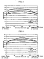
- Fig. 4 is a graph showing an example of change in temperature of a work, grooved rollers, a plate part from the beginning to the end of cutting, when the cutting is conducted according to the method of the present invention.
- Fig. 5 is a view of an example of the shape of a warp of the wafer obtained by cutting with a wire saw according to a conventional method.
- Fig. 6 is a view showing a result of simulation of the shape of a warp of the wafer obtained by cutting with a conventional wire saw using a model of Fig.2.
- Fig. 7 is a view of an example of the shape of a warp of the wafer obtained by cutting with a wire saw according to the method of the present invention.
- Fig. 8 is a view showing a result of simulation of cutting temperature for obtaining the wafer having high flatness and no warp.
-
- The embodiment of the present invention will be described below, but the present invention is not limited thereto.
- First, an example of the wire saw of the present invention will be explained with reference to the drawings. Fig. 1 is a schematic view showing the wire saw of the present invention.
- The wire saw 1 of the present invention consists of a row of wires for cutting process formed by winding a
wire 4 around fourgrooved rollers plate part 6 for positioning and fixing awork 8 on thewire 4 via aspacer 7 and aholder 5 that can move theplate 6 upward and downward, and is installed in aprocessing chamber 10. Nozzles for cuttingfluid 11A, 11B are provided above thegrooved rollers 2A, 2B to supply the cutting fluid 21 to thewire 4. Thewire 4 can be reciprocated by thegrooved roller 2D that is connected to a wire running means 9, and has a function of cutting thework 8 by rubbing it therewith. - The system for supplying a cutting fluid 21 consists of a pipe line system from a cutting
fluid tank 20 equipped with amixer 22 provided outside theprocessing chamber 10, via atemperature controlling apparatus 24, to the above-mentionedcutting fluid nozzles 11A, 11B with apump 23, and a pipe line system via atemperature controlling apparatus 28 to a temperature controllingmedium nozzles 12A, 12B. The cutting fluid 21 of which temperature is controlled is poured directly to thework 8 from the temperature controllingmedium nozzles 12A, 12B in order to control the temperature of thework 8 accurately. A cutting fluid 21 used for cutting and control of the temperature as described above, is collected in a cuttingfluid tank 20 via a cuttingfluid receiver 25. - When the temperature of the cutting fluid supplied to the cutting
fluid nozzle 11A, 11B (for a grooved roller) and the temperature of the cutting fluid supplied to the temperature controllingmedium nozzles 12A, 12B (for a work) are the same,temperature controlling apparatuses temperature controlling apparatus - In an embodiment of the present invention, since the temperature controlling medium supplied to the work is a cutting fluid, the cutting
fluid tank 20 is also used for a cutting fluid supplied to the grooved roller. However, a tank for supplying to a grooved roller can be independent of a tank for supplying to a work, and cutting fluid can be supplied thereto separately. Particularly, when a temperature controlling medium other than a cutting fluid is supplied, such a constitution is adopted. - As another line, compressed air provided by an
air compressor 26 is sprayed directly to thework 8 fromair nozzles 13A, 13B, after the temperature thereof is controlled in a airtemperature controlling apparatus 27, so that the temperature of thework 8 can be controlled accurately. - Cutting of the
work 8 can be conducted using the above-mentioned wire saw 1 by positioning and then fixing thework 8 to aspacer 7 and aplate part 6 respectively with an adhesive, and then attached to theholder 5. Then, theholder 5 is moved downward, toward thewire 4 that is running, and thework 8 is cut by being pressed against thewire 4 on which the cutting fluid 21 is applied. During cutting, the cutting fluid 21 is also poured from the cuttingfluid nozzles 11A, 11B, to thegrooved roller 2A, 2B, so that it may be supplied to the cut surface, and a cutting fluid 21 is poured directly to thework 8 from the temperature controllingmedium nozzle 12A, 12B to control the temperature of thework 8. Furthermore, temperature controlled air can be used as a temperature controlling medium, namely sprayed directly to thework 8 from theair nozzles 13A, 13B to control the temperature of thework 8. The temperature controlling medium is not limited to air. For example, it can be water, or any other medium. - The inventors of the present invention have found that, in order to prevent the large warp from being formed locally near the part where the cutting was started and the part where cutting was terminated of the wafer cut with a conventional wire saw, change in temperature at the beginning of cutting should be made gentle. Furthermore, they conducted simulation by modeling the condition of cutting, considering that the condition determined by simulating the shape of the warp can be applied, and found that the shape of the warp can be predicted with the following simulation.
- Accordingly, the warp can be easily controlled by appropriately controlling the temperature of the work during cutting based on the result of the simulation.
- It is considered that large change in the temperature of the work is formed due to friction heat during cutting of the work may lead to difference in an amount of displacement on each part of the wire saw, resulting in formation of a complex shape of the wafer. Accordingly, modeling was conducted as follows. Fig.2 shows a schematic view for explaining the simulation. In Fig.2, the side of the work, the side of the grooved roller of the wire saw and the like are shown. In Fig.2, the
work 8 adhered to theplate part 6 and thespacer 7 is taken in and out from the right side (occasionally referred to as the operation side) of Fig.2. The right side is occasionally referred to as the apparatus side. - In the simulation, the amount of displacement was considered as for the
work 8, theplate part 6, thegrooved roller 2, and theholder 5. In order to simplify the simulation, it was assumed that linear expansion in each of the above-mentioned part occurred only in an axis direction of the work. The starting point of linear expansion was defined as a center in an axis direction as for the work and the plate part, a position of one third of whole length on the apparatus side as for the grooved roller, and the apparatus side as for the holder. These starting points were defined by experience, and were sufficiently consistent with the results of cutting. The following formula 1 is a calculation formula of displacement vector sum wherein displacement to the right of Fig.2 (the apparatus side) is defined to be plus. - And Vi is represented as follow.
- The test conducted in order to confirm effectiveness of the present invention will be explained below.
- A
work 8 was cut according to the conventional method wherein temperature of the work was not controlled. A silicon single crystal having a diameter of 200 mm was used as thework 8, a piano wire was used as awire 4, a mixture of abrasive grains made of SiC and a coolant liquid was used as a cutting fluid 21. The cutting fluid was poured to thegrooved rollers 2A, 2B using only the grindingnozzles 11A, 11B, to cut out 200 wafers. - The shape of the warp of the resultant wafer was shown in Fig.5. Fig.5 shows a result of measurement with Auto Sort (brand name, manufactured by Tropel corporation). Generally, displacement in a wire saw is large at an edge part of an ingot or an edge part of a grooved roller. Accordingly, the warp of the wafer tends to be large at the edge of the ingot. In the test of the present invention, the warp of the wafer and the change in temperature of each part were evaluated at the edge on the operation side (the side on which the work is taken in and out, namely on the right side of Fig.2).
- As shown in Fig.5, extreme change in shape was occurred at the part cut in the early stage of cutting, resulting in a large warp. The extreme change in the shape of the warp may degrade flatness in a polishing step.
- Change in temperature of each of the ingot (work), a main roller (a grooved roller) and a plate part at that time was shown in Fig.3. Although the temperature of the work was 25°C at the beginning of cutting, it got 43°C or more at a peak during cutting, and it sometimes got 50°C or more. The temperature of the grooved roller increased due to transmission of the cutting heat generated between the work and the wire via the wire. However, the temperature is lower than the temperature of the work and difference of temperature was also small.
- As shown in Fig.3, a cutting area where the work is brought into contact with the wire saw is enlarged rapidly in an early stage of cutting, and an amount of heat generation is increased, change in temperature of the work is rapid. When the ingot is cut 20 mm to a direction of diameter, cutting length is 60 % of a diameter of ingot (in the case of a diameter of 8 inches). Even when the ingot is further cut, a rate of increase in a cutting area is small, so that change in temperature of the work is gentle. Accordingly, it has been found in the present invention that large warp can be prevented from being formed in an early stage of cutting by directly cooling the work to suppress rapid increase in temperature of the work.
- Then, the simulation was confirmed as follows. The simulation of the shape of the warp was conducted with defining linear expansion coefficient of each of the work, the plate part, the grooved roller, the holder and measured change in temperature of each of the work, the plate part, the grooved roller and the holder. The solid line in Fig.6 shows a result of the simulation. It was compared with the shape of section of the wafer actually cut in Test 1 shown in Fig.5, and found to be well consistent therewith, as for large change of the shape in the early stage and the terminating stages of the cutting and as for the shape having a waviness around the center thereof, or the like.
- Since it can be confirmed that the warp and the shape of the wafer can be predicted by simulation as described above, the condition for providing a flat shape was studied by the simulation. Namely, the condition for making change of the shape (warp) in the early stage of cutting small and providing a highly flat wafer. Specifically, the temperature of each part enabling the change of the shape at each cutting position of ± 0.01 µm or less was predicted. The result of the simulation was shown in Fig.8.
- The result of the simulation showed that the wafer wherein the warp is flatter can be sliced when the highest temperature of the work (ingot) is controlled to be less than 35 °C. In the case of the wire saw of the present invention, rapid change in the shape at the early stage and the terminating stage of cutting can be prevented by controlling the temperature as in the simulation. Furthermore, change in the shape such as a waviness or the like of the wafer can also be made small.
- Accordingly, in order to make change in temperature at the early stage of cutting gentle, and to lower the highest temperature during cutting, there was adopted a method comprising providing the temperature controlling medium nozzle for pouring a temperature controlling medium temperature controlled to the work willingly, and cutting the work with pouring the medium.
- The wire saw 1 in Fig.1 was used, and a cutting fluid was poured to the
grooved roller 2A, 2B using the cuttingfluid nozzles 11A, 11B, and a cutting fluid was poured to thework 8 using the temperature controllingmedium nozzles 12A, 12B. - The
work 8 having a diameter of 8 inches was cut with keeping a cutting fluid at a temperature of 25 °C, and cooling it with pouring the cutting fluid to thework 8 from a diagonally upper direction. - At that time, the temperature of the work at the beginning of cutting was 25°C, and was increased to 43°C at peak. Although it was not possible to keep the highest temperature less than 35°C, rapid heat generation at the beginning of cutting can be prevented almost completely.
- The change in temperature during cutting was shown in Fig.4. As shown in Fig.4, change in temperature of the work (ingot) from the beginning of cutting to the time at which it was cut to 20 mm in a direction of a diameter can be controlled to be 10°C or less. Particularly, the change to the time at which the work is cut to 10 mm could be made gentle. The shape of the warp of the wafer obtained by the cutting was shown in Fig.7. It has been found that extreme change of the shape in the early stage of cutting can be prevented, and the method of directly cooling the work with a cutting fluid that is a temperature controlling medium is quite effective. Since a sufficient amount of the cutting fluid cannot be supplied to the cutting position only by pouring the cutting fluid directly to the work, the cutting fluid was also supplied to the grooved roller. Thereby, the sufficient amount of the cutting fluid can be supplied to the cutting position, and change in temperature of the grooved roller itself can be controlled.
- The wire saw 1 in Fig.1 was used, and a cutting fluid was supplied to the wire with the cutting
fluid nozzles 11A, 11B, and an air was supplied to the work with theair nozzles 13A, 13B. - The cutting fluid was kept at a temperature of 25°C, and poured to the
grooved rollers 2A, 2B. The air was kept at a temperature of 25°C, and directly sprayed to thework 8 having a diameter of 8 inches from a diagonally upper direction, so that thework 8 was cut with cooling. - At that time, the temperature of the work at the beginning of cutting was 25°C, and was increased to 48°C at peak. However, rapid heat generation at the beginning of cutting can be prevented almost completely.
- The shape of the warp of the wafer obtained by the cutting was approximately the same as the shape of the wafer obtained in Test 3 (See Fig.7). It has been found that extreme change of the shape in the early stage of cutting can be prevented, and the method of cooling with air is also effective. Change in temperature of the work from the beginning of cutting to the time at which it was cut to 20 mm in a direction of a diameter could also be controlled to be 10°C or less.
- The method of heating the work was tested. The peak temperature of the work during cutting of 45°C obtained by the conventional method of Test 1 was defined as the predetermined temperature of the work that had been previously defined.
- The wire saw shown in Fig.1 was used, and the temperature controlling
medium nozzles 12A, 12B was used together with the cuttingfluid nozzles 11A, 11B. - The work was previously heated to about 45°C by oven, before the work was set on the wire saw, and then the work was set on the wire saw. Then, it was heated to 45°C with a heater provided at the plate part, the cutting fluid of which temperature was controlled to be 25°C was supplied to the
grooved rollers 2A, 2B and also poured directly to thework 8 from a diagonally upper direction, and then cutting was initiated. - At that time, the temperature of the work at the beginning of cutting was 47°C, and was increased to 52°C at peak. However, change in temperature during cutting can be made small. The shape of the warp of the wafer obtained by the cutting was approximately the same as the shape of the wafer obtained in Fig.7 of
Test 3. There was no extreme change of the shape in the early stage or the terminating stage of cutting. - From the results of the simulation, it has been found that the better warp can be produced by controlling whole change in temperature of the work from the beginning to the end of cutting to be 10°C or less. Namely, if the work was cut with controlling the highest temperature during cutting may be less than 35°C that is 10°C higher than 25°C that is a temperature before cutting by pouring the cutting fluid and the cooled air, the wafer having somewhat smaller warp than that of
Test 3 shown in Fig.7 could be obtained, and it was well consistent with the tendency of the simulation although completely the same control as the temperature distribution in the simulation cannot be achieved. - As described above, if the temperature of the work is controlled by cooling the whole of the work to the predetermined temperature directly with the temperature controlling medium or by preheating the work, particularly so that change in temperature at the early stage may be gentle, difference in heat expansion between the work and the wire saw can be made small, and the extreme change of the shape in the early stage of cutting can be prevented, the warp can be made small. As a result, the wafer having a desired shape of the warp can be sliced out. Furthermore, an appropriate condition for cutting can be selected by simulating the shape of the warp.
- Another means for controlling willingly can be a temperature controlling means provided at a plate part supporting the work. The temperature of the work during cutting can also be controlled accurately thereby.
- The present invention is not limited to the above-described embodiment. The above-described embodiment is a mere example, and those having the substantially same structure as technical idea that described in the appended claims and providing the similar action and effects are included in the scope of the present invention.
- For example, in the above-mentioned embodiment of the present invention, the silicon wafer having a diameter of 200 mm (8 inches) was sliced. However, the present invention can also be applied to the recent larger wafer having a diameter of 250 mm (10 inches) - 400 mm (16 inches) or more.
- The wire saw having four grooved rollers was used in the above embodiment. However, the another type of the wire saw can be used. Specifically, the similar effect can be achieved in the wire saw having three or two grooved rollers.
Claims (10)
- A cutting method comprising winding a wire around plural grooved rollers, and pressing the wire against the work with running it, to cut the work, wherein the work is cut with controlling temperature of the work by supplying a cutting fluid containing abrasive grains to the grooved rollers, and supplying a temperature controlling medium to the work.
- A cutting method comprising winding a wire around plural grooved rollers, and pressing the wire against the work with running it, to cut the work, wherein a temperature of the work is previously defined at a predetermined value, and the work is cut with supplying a cutting fluid containing abrasive grains to the grooved rollers.
- A cutting method comprising winding a wire around plural grooved rollers, and pressing the wire against the work with running it, to cut the work wherein a temperature of the work is previously defined at a predetermined temperature, and the work is cut with controlling a temperature of the work by supplying a cutting fluid to the grooved rollers, and supplying a temperature controlling medium to the work.
- The cutting method according to any one of claims 1 to 3 wherein change in temperature of the work in a period from the beginning of the cutting process to the time when a cutting length reaches 60% of a diameter of the work and/or in a period from the time when a cutting length reaches 60% of a diameter of the work to the end of the cutting process in the latter half of the cutting is controlled to be 10°C or less.
- The cutting method according to any one of claims 1 to 4 wherein the temperature of the work can be predetermined so that a shape of the warp of the wafer defined by simulation with coefficient of linear expansion and temperature of each part of the work and the wire saw can be flat.
- The cutting method according to any one of claims 1 to 5 wherein the temperature controlling medium is a cutting fluid of which temperature is controlled and/or an air of which temperature is controlled.
- The cutting method according to any one of claims 1 to 6 wherein the temperature of the work during cutting is kept lower than 35°C.
- The cutting method according to any one of claims 1 to 7 wherein the temperature of the plate part for supporting the work is controlled.
- A wire saw wherein a wire is wound around plural grooved rollers, and a work is cut by pressing the wire against the work with running the wire, comprising a means for supplying a cutting fluid containing abrasive grains of which temperature is controlled to the grooved rollers, a means for pouring a cutting fluid containing abrasive grains of which temperature is controlled directly to the work or a means for spraying a medium of which temperature is controlled directly to the work.
- The wire saw according to claim 9 that is equipped with a temperature controlling means at a plate part for supporting the work.
Applications Claiming Priority (3)
| Application Number | Priority Date | Filing Date | Title |
|---|---|---|---|
| JP1168099 | 1999-01-20 | ||
| JP1168099 | 1999-01-20 | ||
| PCT/JP2000/000155 WO2000043162A1 (en) | 1999-01-20 | 2000-01-14 | Wire saw and cutting method |
Publications (3)
| Publication Number | Publication Date |
|---|---|
| EP1097782A1 true EP1097782A1 (en) | 2001-05-09 |
| EP1097782A4 EP1097782A4 (en) | 2005-05-18 |
| EP1097782B1 EP1097782B1 (en) | 2006-11-15 |
Family
ID=11784725
Family Applications (1)
| Application Number | Title | Priority Date | Filing Date |
|---|---|---|---|
| EP00900395A Expired - Lifetime EP1097782B1 (en) | 1999-01-20 | 2000-01-14 | Wire saw and cutting method |
Country Status (6)
| Country | Link |
|---|---|
| US (1) | US6652356B1 (en) |
| EP (1) | EP1097782B1 (en) |
| JP (1) | JP3734018B2 (en) |
| KR (1) | KR100607188B1 (en) |
| DE (1) | DE60031823T2 (en) |
| WO (1) | WO2000043162A1 (en) |
Cited By (7)
| Publication number | Priority date | Publication date | Assignee | Title |
|---|---|---|---|---|
| US6773333B2 (en) * | 2001-05-10 | 2004-08-10 | Siltronic Ag | Method for cutting slices from a workpiece |
| GB2414204A (en) * | 2004-05-18 | 2005-11-23 | David Ainsworth Hukin | Abrasive wire sawing |
| WO2007087510A1 (en) * | 2006-01-26 | 2007-08-02 | Memc Electronic Materials, Inc. | Wire saw ingot slicing system and method with ingot preheating, web preheating, slurry temperature control and/or slurry flow rate control |
| EP2065922A1 (en) * | 2006-09-22 | 2009-06-03 | Shin-Etsu Handotai Co., Ltd. | Cutting method |
| CN102189611A (en) * | 2011-04-15 | 2011-09-21 | 浙江德圣龙新材料科技有限公司 | Equidensity mortar cutting method and device for linear cutting of solar wafer |
| CN102241083A (en) * | 2011-07-12 | 2011-11-16 | 浙江德圣龙新材料科技有限公司 | Isoviscous mortar cutting method and device used for wire-electrode cutting of solar silicon wafer |
| CN104290206A (en) * | 2014-09-18 | 2015-01-21 | 苏州市汇峰机械设备有限公司 | Wire cutting machine mortar device |
Families Citing this family (33)
| Publication number | Priority date | Publication date | Assignee | Title |
|---|---|---|---|---|
| US20030170948A1 (en) * | 2002-03-07 | 2003-09-11 | Memc Electronic Materials, Inc. | Method and apparatus for slicing semiconductor wafers |
| JP4839137B2 (en) * | 2006-06-05 | 2011-12-21 | トーヨーエイテック株式会社 | Wire saw |
| JP4991229B2 (en) * | 2006-09-22 | 2012-08-01 | 信越半導体株式会社 | Cutting method and epitaxial wafer manufacturing method |
| JP4965949B2 (en) | 2006-09-22 | 2012-07-04 | 信越半導体株式会社 | Cutting method |
| JP4816511B2 (en) * | 2007-03-06 | 2011-11-16 | 信越半導体株式会社 | Cutting method and wire saw device |
| JP5003294B2 (en) | 2007-06-08 | 2012-08-15 | 信越半導体株式会社 | Cutting method |
| JP2009029078A (en) * | 2007-07-30 | 2009-02-12 | Toyo Advanced Technologies Co Ltd | Wire saw device |
| US7959491B2 (en) * | 2007-12-19 | 2011-06-14 | Shin-Etsu Handotai Co., Ltd. | Method for slicing workpiece by using wire saw and wire saw |
| KR20100120685A (en) * | 2008-02-11 | 2010-11-16 | 엠이엠씨 일렉트로닉 머티리얼즈, 인크. | Carbon nanotube reinforced wiresaw beam used in wiresaw slicing of ingots into wafers |
| JP5007706B2 (en) * | 2008-06-30 | 2012-08-22 | 信越半導体株式会社 | Work cutting method |
| JP2010029955A (en) * | 2008-07-25 | 2010-02-12 | Shin Etsu Handotai Co Ltd | Method for resuming operation of wire saw and wire saw |
| JP2010030074A (en) * | 2008-07-25 | 2010-02-12 | Nippon Fuasutemu Kk | Wire saw cutting device |
| JP5151851B2 (en) * | 2008-09-19 | 2013-02-27 | 信越半導体株式会社 | Band saw cutting device and ingot cutting method |
| US8065995B2 (en) * | 2008-11-25 | 2011-11-29 | Cambridge Energy Resources Inc | Method and apparatus for cutting and cleaning wafers in a wire saw |
| US8261730B2 (en) * | 2008-11-25 | 2012-09-11 | Cambridge Energy Resources Inc | In-situ wafer processing system and method |
| JP5515593B2 (en) * | 2009-10-07 | 2014-06-11 | 株式会社Sumco | Method for cutting silicon ingot with wire saw and wire saw |
| KR20120037576A (en) * | 2010-10-12 | 2012-04-20 | 주식회사 엘지실트론 | Sawing apparatus of single crystal and sawing method of single crystal |
| DE102011008400B4 (en) | 2011-01-12 | 2014-07-10 | Siltronic Ag | Method for cooling a workpiece made of semiconductor material during wire sawing |
| DE102011005948B4 (en) * | 2011-03-23 | 2012-10-31 | Siltronic Ag | Method for separating slices from a workpiece |
| DE102011005949B4 (en) * | 2011-03-23 | 2012-10-31 | Siltronic Ag | Method for separating slices from a workpiece |
| JP5427822B2 (en) * | 2011-04-05 | 2014-02-26 | ジルトロニック アクチエンゲゼルシャフト | How to cut a workpiece with a wire saw |
| US20130144421A1 (en) * | 2011-12-01 | 2013-06-06 | Memc Electronic Materials, Spa | Systems For Controlling Temperature Of Bearings In A Wire Saw |
| TWI567812B (en) * | 2011-12-01 | 2017-01-21 | Memc電子材料公司 | Systems and methods for controlling surface profiles of wafers sliced in a wire saw |
| DE102012201938B4 (en) * | 2012-02-09 | 2015-03-05 | Siltronic Ag | A method of simultaneously separating a plurality of slices from a workpiece |
| JP5954251B2 (en) * | 2013-05-02 | 2016-07-20 | 信越半導体株式会社 | Wafer chamfering apparatus and wafer chamfering method |
| KR101540568B1 (en) * | 2014-01-06 | 2015-07-31 | 주식회사 엘지실트론 | A wire sawing apparatus and method |
| JP2016058675A (en) * | 2014-09-12 | 2016-04-21 | 株式会社東芝 | Polishing device and polishing method of semiconductor wafer |
| KR101710927B1 (en) * | 2015-06-08 | 2017-02-28 | 주식회사 엘지실트론 | Ingot Cutting Apparatus |
| US9978582B2 (en) * | 2015-12-16 | 2018-05-22 | Ostendo Technologies, Inc. | Methods for improving wafer planarity and bonded wafer assemblies made from the methods |
| JP7427921B2 (en) * | 2019-11-12 | 2024-02-06 | 株式会社Sumco | Method for determining slicing processing conditions for semiconductor ingots and method for manufacturing semiconductor wafers |
| EP3858569A1 (en) * | 2020-01-28 | 2021-08-04 | Siltronic AG | Method for separating a plurality of slices from workpieces by means of a wire saw during a sequence of separation operations |
| CN111531722A (en) * | 2020-05-28 | 2020-08-14 | 广州市黄埔建筑工程总公司 | Method for cutting and dismantling supporting beam of foundation pit support by using wire saw |
| US11717930B2 (en) * | 2021-05-31 | 2023-08-08 | Siltronic Corporation | Method for simultaneously cutting a plurality of disks from a workpiece |
Citations (7)
| Publication number | Priority date | Publication date | Assignee | Title |
|---|---|---|---|---|
| JPH01306171A (en) * | 1988-06-02 | 1989-12-11 | Osaka Titanium Co Ltd | Cutting method and wire saw machine |
| JPH06155450A (en) * | 1992-11-19 | 1994-06-03 | Sumitomo Metal Ind Ltd | Cutting method with multiple wire saw |
| JPH071442A (en) * | 1993-06-18 | 1995-01-06 | Shin Etsu Chem Co Ltd | Manufacture of wafer |
| EP0745464A2 (en) * | 1995-06-01 | 1996-12-04 | Shin-Etsu Handotai Co., Ltd | Wire saw slicing apparatus and slicing method using the same |
| JPH10217036A (en) * | 1997-01-29 | 1998-08-18 | Komatsu Electron Metals Co Ltd | Semiconductor crystal bar cutting device and method |
| JPH1158365A (en) * | 1997-08-25 | 1999-03-02 | Mitsubishi Materials Shilicon Corp | Wire saw and method for cutting ingot |
| JPH11216656A (en) * | 1998-01-30 | 1999-08-10 | Toshiba Ceramics Co Ltd | Work cutting method by wire saw |
Family Cites Families (6)
| Publication number | Priority date | Publication date | Assignee | Title |
|---|---|---|---|---|
| JP2673544B2 (en) * | 1988-06-14 | 1997-11-05 | 株式会社日平トヤマ | Cutting method for brittle materials |
| JP2516717B2 (en) * | 1991-11-29 | 1996-07-24 | 信越半導体株式会社 | Wire saw and its cutting method |
| CH687301A5 (en) * | 1992-01-22 | 1996-11-15 | W S Technologies Ltd | Wire sawing device. |
| JPH0985737A (en) * | 1995-09-22 | 1997-03-31 | Toray Eng Co Ltd | Wire type cutting device |
| JPH10138231A (en) * | 1996-11-07 | 1998-05-26 | Toshiba Ceramics Co Ltd | Wire saw |
| JPH11221748A (en) * | 1998-02-06 | 1999-08-17 | Toray Eng Co Ltd | Wire saw |
-
2000
- 2000-01-14 US US09/623,921 patent/US6652356B1/en not_active Expired - Lifetime
- 2000-01-14 DE DE60031823T patent/DE60031823T2/en not_active Expired - Lifetime
- 2000-01-14 EP EP00900395A patent/EP1097782B1/en not_active Expired - Lifetime
- 2000-01-14 JP JP2000594609A patent/JP3734018B2/en not_active Expired - Fee Related
- 2000-01-14 WO PCT/JP2000/000155 patent/WO2000043162A1/en active IP Right Grant
- 2000-01-14 KR KR1020007010180A patent/KR100607188B1/en active IP Right Grant
Patent Citations (7)
| Publication number | Priority date | Publication date | Assignee | Title |
|---|---|---|---|---|
| JPH01306171A (en) * | 1988-06-02 | 1989-12-11 | Osaka Titanium Co Ltd | Cutting method and wire saw machine |
| JPH06155450A (en) * | 1992-11-19 | 1994-06-03 | Sumitomo Metal Ind Ltd | Cutting method with multiple wire saw |
| JPH071442A (en) * | 1993-06-18 | 1995-01-06 | Shin Etsu Chem Co Ltd | Manufacture of wafer |
| EP0745464A2 (en) * | 1995-06-01 | 1996-12-04 | Shin-Etsu Handotai Co., Ltd | Wire saw slicing apparatus and slicing method using the same |
| JPH10217036A (en) * | 1997-01-29 | 1998-08-18 | Komatsu Electron Metals Co Ltd | Semiconductor crystal bar cutting device and method |
| JPH1158365A (en) * | 1997-08-25 | 1999-03-02 | Mitsubishi Materials Shilicon Corp | Wire saw and method for cutting ingot |
| JPH11216656A (en) * | 1998-01-30 | 1999-08-10 | Toshiba Ceramics Co Ltd | Work cutting method by wire saw |
Non-Patent Citations (7)
| Title |
|---|
| PATENT ABSTRACTS OF JAPAN vol. 014, no. 097 (M-0940), 22 February 1990 (1990-02-22) -& JP 01 306171 A (OSAKA TITANIUM CO LTD), 11 December 1989 (1989-12-11) * |
| PATENT ABSTRACTS OF JAPAN vol. 018, no. 474 (M-1668), 5 September 1994 (1994-09-05) -& JP 06 155450 A (SUMITOMO METAL IND LTD), 3 June 1994 (1994-06-03) * |
| PATENT ABSTRACTS OF JAPAN vol. 1995, no. 04, 31 May 1995 (1995-05-31) -& JP 07 001442 A (SHIN ETSU CHEM CO LTD), 6 January 1995 (1995-01-06) * |
| PATENT ABSTRACTS OF JAPAN vol. 1998, no. 13, 30 November 1998 (1998-11-30) -& JP 10 217036 A (KOMATSU ELECTRON METALS CO LTD), 18 August 1998 (1998-08-18) * |
| PATENT ABSTRACTS OF JAPAN vol. 1999, no. 08, 30 June 1999 (1999-06-30) -& JP 11 058365 A (MITSUBISHI MATERIALS SHILICON CORP), 2 March 1999 (1999-03-02) * |
| PATENT ABSTRACTS OF JAPAN vol. 1999, no. 13, 30 November 1999 (1999-11-30) -& JP 11 216656 A (TOSHIBA CERAMICS CO LTD), 10 August 1999 (1999-08-10) * |
| See also references of WO0043162A1 * |
Cited By (12)
| Publication number | Priority date | Publication date | Assignee | Title |
|---|---|---|---|---|
| US6773333B2 (en) * | 2001-05-10 | 2004-08-10 | Siltronic Ag | Method for cutting slices from a workpiece |
| GB2414204A (en) * | 2004-05-18 | 2005-11-23 | David Ainsworth Hukin | Abrasive wire sawing |
| GB2414204B (en) * | 2004-05-18 | 2006-04-12 | David Ainsworth Hukin | Abrasive wire sawing |
| US7461648B2 (en) | 2004-05-18 | 2008-12-09 | Rec Scanwafer As | Abrasive wire sawing |
| WO2007087510A1 (en) * | 2006-01-26 | 2007-08-02 | Memc Electronic Materials, Inc. | Wire saw ingot slicing system and method with ingot preheating, web preheating, slurry temperature control and/or slurry flow rate control |
| US7878883B2 (en) | 2006-01-26 | 2011-02-01 | Memc Electronics Materials, Inc. | Wire saw ingot slicing system and method with ingot preheating, web preheating, slurry temperature control and/or slurry flow rate control |
| EP2065922A1 (en) * | 2006-09-22 | 2009-06-03 | Shin-Etsu Handotai Co., Ltd. | Cutting method |
| EP2065922A4 (en) * | 2006-09-22 | 2013-10-02 | Shinetsu Handotai Kk | Cutting method |
| CN102189611A (en) * | 2011-04-15 | 2011-09-21 | 浙江德圣龙新材料科技有限公司 | Equidensity mortar cutting method and device for linear cutting of solar wafer |
| CN102189611B (en) * | 2011-04-15 | 2013-11-27 | 浙江德圣龙新材料科技有限公司 | Equidensity mortar cutting method for linear cutting of solar wafer |
| CN102241083A (en) * | 2011-07-12 | 2011-11-16 | 浙江德圣龙新材料科技有限公司 | Isoviscous mortar cutting method and device used for wire-electrode cutting of solar silicon wafer |
| CN104290206A (en) * | 2014-09-18 | 2015-01-21 | 苏州市汇峰机械设备有限公司 | Wire cutting machine mortar device |
Also Published As
| Publication number | Publication date |
|---|---|
| DE60031823T2 (en) | 2007-09-13 |
| KR20010092236A (en) | 2001-10-24 |
| US6652356B1 (en) | 2003-11-25 |
| JP3734018B2 (en) | 2006-01-11 |
| KR100607188B1 (en) | 2006-08-01 |
| EP1097782A4 (en) | 2005-05-18 |
| WO2000043162A1 (en) | 2000-07-27 |
| DE60031823D1 (en) | 2006-12-28 |
| EP1097782B1 (en) | 2006-11-15 |
Similar Documents
| Publication | Publication Date | Title |
|---|---|---|
| US6652356B1 (en) | Wire saw and cutting method | |
| JP4076130B2 (en) | How to detach a substrate from a workpiece | |
| US7878883B2 (en) | Wire saw ingot slicing system and method with ingot preheating, web preheating, slurry temperature control and/or slurry flow rate control | |
| JP5492239B2 (en) | Method for slicing a wafer from a workpiece | |
| JP2885270B2 (en) | Wire saw device and work cutting method | |
| KR20100020463A (en) | Cutting method and wire saw device | |
| JP2969071B2 (en) | Polishing equipment | |
| TW201107102A (en) | Method for producing a semiconductor wafer | |
| JP5449435B2 (en) | Method for slicing a wafer from a workpiece | |
| US7097534B1 (en) | Closed-loop control of a chemical mechanical polisher | |
| JP2000141220A (en) | Work plate temperature control device of wire saw | |
| KR100780099B1 (en) | Work holding panel for polishing, and device and method for polishing | |
| JPH06155450A (en) | Cutting method with multiple wire saw | |
| JP2571488B2 (en) | Method and apparatus for cutting workpiece by wire saw | |
| JP2014213403A (en) | Method for reducing warpage of substrate, method for manufacturing substrate, and sapphire substrate | |
| EP0934801B1 (en) | Method for polishing work | |
| JP2005116689A (en) | Vapor phase epitaxial growth method and vapor phase epitaxial growth system | |
| JP2015502268A (en) | Wire guide for ingot cutting, wire saw apparatus including the same, and ingot cutting method | |
| JP3037047B2 (en) | Semiconductor manufacturing equipment | |
| JP3907421B2 (en) | Polishing work holding disk, polishing apparatus, and polishing method | |
| JPH08243915A (en) | Chemical machine polishing device | |
| JP2012033762A (en) | Method and equipment for manufacturing semiconductor wafer | |
| JP2008016816A (en) | Thin film planarization method of semiconductor device | |
| JP2000158330A (en) | Manufacturing device for highly flat material | |
| TW202302308A (en) | Device for cutting silicon rod |
Legal Events
| Date | Code | Title | Description |
|---|---|---|---|
| PUAI | Public reference made under article 153(3) epc to a published international application that has entered the european phase |
Free format text: ORIGINAL CODE: 0009012 |
|
| 17P | Request for examination filed |
Effective date: 20000928 |
|
| AK | Designated contracting states |
Kind code of ref document: A1 Designated state(s): DE GB IT |
|
| A4 | Supplementary search report drawn up and despatched |
Effective date: 20050406 |
|
| RIC1 | Information provided on ipc code assigned before grant |
Ipc: 7B 28D 5/04 B Ipc: 7B 24B 27/06 A Ipc: 7B 28D 5/00 B |
|
| GRAP | Despatch of communication of intention to grant a patent |
Free format text: ORIGINAL CODE: EPIDOSNIGR1 |
|
| GRAS | Grant fee paid |
Free format text: ORIGINAL CODE: EPIDOSNIGR3 |
|
| GRAA | (expected) grant |
Free format text: ORIGINAL CODE: 0009210 |
|
| AK | Designated contracting states |
Kind code of ref document: B1 Designated state(s): DE GB IT |
|
| PG25 | Lapsed in a contracting state [announced via postgrant information from national office to epo] |
Ref country code: IT Free format text: LAPSE BECAUSE OF FAILURE TO SUBMIT A TRANSLATION OF THE DESCRIPTION OR TO PAY THE FEE WITHIN THE PRESCRIBED TIME-LIMIT;WARNING: LAPSES OF ITALIAN PATENTS WITH EFFECTIVE DATE BEFORE 2007 MAY HAVE OCCURRED AT ANY TIME BEFORE 2007. THE CORRECT EFFECTIVE DATE MAY BE DIFFERENT FROM THE ONE RECORDED. Effective date: 20061115 |
|
| REG | Reference to a national code |
Ref country code: GB Ref legal event code: FG4D |
|
| REF | Corresponds to: |
Ref document number: 60031823 Country of ref document: DE Date of ref document: 20061228 Kind code of ref document: P |
|
| PLBE | No opposition filed within time limit |
Free format text: ORIGINAL CODE: 0009261 |
|
| STAA | Information on the status of an ep patent application or granted ep patent |
Free format text: STATUS: NO OPPOSITION FILED WITHIN TIME LIMIT |
|
| 26N | No opposition filed |
Effective date: 20070817 |
|
| PGFP | Annual fee paid to national office [announced via postgrant information from national office to epo] |
Ref country code: GB Payment date: 20190109 Year of fee payment: 20 Ref country code: DE Payment date: 20190102 Year of fee payment: 20 |
|
| REG | Reference to a national code |
Ref country code: DE Ref legal event code: R071 Ref document number: 60031823 Country of ref document: DE |
|
| REG | Reference to a national code |
Ref country code: GB Ref legal event code: PE20 Expiry date: 20200113 |
|
| PG25 | Lapsed in a contracting state [announced via postgrant information from national office to epo] |
Ref country code: GB Free format text: LAPSE BECAUSE OF EXPIRATION OF PROTECTION Effective date: 20200113 |