EP1096540A1 - Kathodenstrahlröhre mit verbesserter Elektrodenanordnung - Google Patents
Kathodenstrahlröhre mit verbesserter Elektrodenanordnung Download PDFInfo
- Publication number
- EP1096540A1 EP1096540A1 EP00123351A EP00123351A EP1096540A1 EP 1096540 A1 EP1096540 A1 EP 1096540A1 EP 00123351 A EP00123351 A EP 00123351A EP 00123351 A EP00123351 A EP 00123351A EP 1096540 A1 EP1096540 A1 EP 1096540A1
- Authority
- EP
- European Patent Office
- Prior art keywords
- electrode
- electrode member
- electron beam
- plate
- cup
- Prior art date
- Legal status (The legal status is an assumption and is not a legal conclusion. Google has not performed a legal analysis and makes no representation as to the accuracy of the status listed.)
- Withdrawn
Links
Images




Classifications
-
- H—ELECTRICITY
- H01—ELECTRIC ELEMENTS
- H01J—ELECTRIC DISCHARGE TUBES OR DISCHARGE LAMPS
- H01J29/00—Details of cathode-ray tubes or of electron-beam tubes of the types covered by group H01J31/00
- H01J29/46—Arrangements of electrodes and associated parts for generating or controlling the ray or beam, e.g. electron-optical arrangement
- H01J29/48—Electron guns
- H01J29/485—Construction of the gun or of parts thereof
Definitions
- the present invention relates to a cathode ray tube, and in particular to a cathode ray tube having reliability enhanced by improving welding accuracy of an electrode fabricated by stacking and welding together a plurality of electrode members in an electron gun housed in its vacuum envelope.
- Color cathode ray tubes such as a color picture tube and a display tube, which are typical cathode ray tubes, are widely used for reception of TV broadcast and monitors of various kinds of information processing equipment because of their high-definition image reproduction capability.
- Color cathode ray tubes of such a kind have a vacuum envelope comprised of a panel, a neck and a funnel for connecting the panel and the neck, a phosphor screen formed on an inner surface of the panel, and an electron gun housed in the neck for projecting an electron beam toward the phosphor screen.
- color cathode ray tubes employing an in-line type electron for projecting a plurality of electron beams parallel with each other in a horizontal plane.
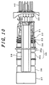
- FIG. 10 is a side view of an essential part of an embodiment of a configuration of an in-line type electron gun used for a color cathode ray tube, viewed in a direction perpendicular to a direction of the in-line arrangement of electron beams.
- reference numeral 31 denotes cathodes
- 32 is a first electrode serving as a control electrode
- 33 is a second electrode serving as an accelerating electrode
- the cathodes 31 the first electrode 32 and the second electrode 33 form an electron beam generating section.
- Reference numeral 34 denotes a third electrode
- 35 is a fourth electrode.
- the fourth electrode 35 are formed of two tube-like electrodes 35a and 35b, and they serve as two focus electrodes.
- Reference numeral 36 denotes a fifth electrode, and the fifth electrode 36 and the tube-like electrode 35b of the fourth electrode 35which forms a main lens therebetween.
- Reference numeral 37 denotes a shield cup, which is welded to the fifth electrode 36.
- the cathodes 31 and the first to fifth electrodes 32-36 are spaced with predetermined spacings and fixed in the predetermined order by a pair of insulator support rods (multiform glasses) 38.
- Reference numeral 39 denotes a stem, and the cathodes and the electrodes are supplied with display signals or operating voltages via stem pins 40 sealed through the stem 39.
- Three electron beams are generated by the electron beam generating section which is a triode section comprised of the cathodes 31, the first electrode 32 and the second electrode 33, and are accelerated and focused by the third electrode 34, the fourth electrode 35 and the fifth electrode 36 such that the three electron beams are subjected to a desired focusing action by the main lens formed between opposing end faces of the fifth electrode 36 and the electrode 35b of the fourth electrode 35 and then directed toward the phosphor screen.
- the first electrode 32 and the second electrode 33 are plate-like electrodes
- the third electrode 34 and the fourth electrode 35 are compound electrodes fabricated by stacking and welding together plural electrode members including a cup-shaped electrode member and a plate-like member.
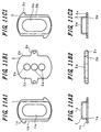
- FIGS. 11A1, 11A2, 11B1, 11B2, 11C1 and 11C2 are plan views and side views of electrode members forming the compound electrode shown in FIG. 10.
- FIGS. 11A1 and 11A2 are plan and side views of a first electrode member 1, respectively
- FIGS. 11B1 and 11B2 are plan and side views of a second electrode member 2, respectively
- FIGS. 11C1 and 11C2 are plan and side views of a third electrode member 3, respectively.
- the first electrode member 1 and the third electrode member 3 are attached and welded by laser to the top and bottom surfaces of the second electrode member 2, respectively.
- the first electrode member 1 and the third electrode member 3 are cup-shaped electrode members having rims 1b and 3b, respectively, and are formed by a drawing press.
- the second electrode member 2 are a plate electrode thicker than the first electrode member 1 and the third electrode member 3.
- the first electrode member 1 is formed with a single opening (an electron beam-transmissive opening) 1a in a bottom at an end of its cup shape and the rim 1b at the other end of the cup shape.
- the rim 1b is formed with a protrusion 1c in a corner thereof for rotational alignment of the first electrode member 1 in an assembly or welding an electrical lead thereto for applying a voltage to the first electrode member 1.
- the third electrode member 3 is formed with a single opening (an electron beam-transmissive opening) 3a in a bottom at an end of its cup shape and the rim 3b at the other end of the cup shape.
- the rim 3b is formed with a protrusion 3c in a corner thereof for indicating a position of the third electrode member 3 in an assembly or welding an electrical lead thereto for applying a voltage to the third electrode member 3.
- the second electrode member 2 is formed with three electron beam-transmissive apertures 2a in its central portion on its major axis.
- the second electrode member 2 is fabricated by a simple punching which pierces the three apertures in a thick metal plate simultaneously with blanking, or trimming.
- An edge 2b is used for welding and is provided with tabs 2c approximately at centers at the respective long sides of the second electrode member 2 for being embedded into the insulator support rods (multiform glasses) 38 and thereby being fixed.
- FIGS. 12A, 12B and 12C are illustrations for explaining a structure of a compound electrode integrally assembled and its welded condition
- FIG. 8A is a plan view of the compound electrode
- FIG. 12B is a cross-sectional view of the whole structure of the compound electrode of FIG. 12A taken along line VIIIB-VIIIB of FIG. 12A
- FIG. 12C is an enlarged cross-sectional view of an essential part of a welded portion in a cross section of the compound electrode of FIG. 12A taken along line VIIIC-VIIIC of FIG. 12A.
- FIG. 12A two positions corresponding to a pair of insulator support rods (multiform glasses) 38 are indicated by two-dot chain lines.
- the first electrode member 1 and the third electrode member 3 are attached to the top and bottom surfaces of the second electrode member 2, respectively, such that the edge of the rim 1b of the first electrode member 1 and the edge of the rim 3b of the third electrode member 3 are aligned with the edge 2b of the second electrode member 2, and then they are welded together by irradiating a laser beam onto the edges of the interface between the adjacent electrode members.
- the weld points are denoted by "W ⁇ ".
- the first, second and third electrodes 1, 2, 3 are attached together, and then, as shown in FIG. 12C, they are welded together by irradiating a laser beam L horizontally onto the edges of the interface between the mutually adjacent electrode members.
- the laser welding in this case employs a multiple-beam multiple-spot welding method capable of welding two or more spots simultaneously.
- the weld points are denoted by circles " ⁇ ".
- the above-explained compound electrodes are not limited to one comprised of three electrode members as explained above, but are applicable to one comprised of a plate-like electrode member and a cup-shaped electrode member stacked and welded on the plate-like electrode member.
- Welding of the stacked electrode members is performed by irradiating a laser beam L horizontally onto the interface of the stacked edges of the electrode members, as shown in FIG. 12C.
- the laser welding in this case employs a multiple-beam multiple-spot welding method capable of welding two or more spots simultaneously.
- two laser beams L perform welding of the first and second electrode members 1, 2 and welding of the second and third electrode members 2, 3, respectively, at the same time.
- Reference numeral 100 denote lenses.
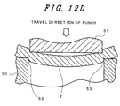
- Both of the two laser beams L having the same focal length are focused onto the edges of the stacked electrode members, and this means that, in the case of welding an edge of the second electrode member 2 having the shear droop, the laser beam L is focused onto the interface between the edge of the first electrode member 1 and a point of the edge of the second electrode member 2 where the shear droop begins, as shown in FIG. 12C. Therefore, a weld point of the first and second electrode members 1, 2 is displaced from a focal point of the laser beam by a distance D (D ⁇ 0). Consequently, the energy of the laser beam becomes weak in the innermost of the shear droop, resulting in so-called weak welding.
- the welding strength in the innermost of the shear droop is poor such that a compound electrode is not sufficiently integrally assembled, thereby sufficient assembling accuracy is not achieved, and further it is difficult to attain long lifetime of a cathode ray tube because of variations of performance characteristics due to aging.
- a cathode ray tube comprising an evacuated envelope including a panel portion, a neck portion and a funnel portion for connecting the panel portion and the neck portion, a phosphor screen formed on an inner surface of the panel portion, and an electron gun housed in the neck portion;
- the electron gun comprising an electron beam generating section having a cathode, an electron beam control electrode and an accelerating electrode arranged in the order named for projecting an electron beam toward the phosphor screen, and an electron beam focusing section for focusing the electron beam from the electron beam generating section onto the phosphor screen, the electron beam generating section and the electron beam focusing section being mounted in predetermined spaced relationship on a plurality of insulator support rods, the electron beam focusing section including at least one compound electrode comprising a first electrode member, a second electrode member and a plate-like electrode member sandwiched therebetween, the plate-like electrode member being fabricated from a material thicker than materials from which the
- a cathode ray tube comprising an evacuated envelope including a panel portion, a neck portion and a funnel portion for connecting the panel portion and the neck portion, a phosphor screen formed on an inner surface of the panel portion, and an electron gun housed in the neck portion;
- the electron gun comprising an electron beam generating section having a cathode, an electron beam control electrode and an accelerating electrode arranged in the order named for projecting an electron beam toward the phosphor screen, and an electron beam focusing section for focusing the electron beam from the electron beam generating section onto the phosphor screen, the electron beam generating section and the electron beam focusing section being mounted in predetermined spaced relationship on a plurality of insulator support rods, the electron beam focusing section including at least one compound electrode comprising a first cup-shaped electrode member having a flange at an open end thereof, a second cup-shaped electrode member having a flange at an open end thereof and a plate-like
- a cathode ray tube comprising an evacuated envelope including a panel portion, a neck portion and a funnel portion for connecting the panel portion and the neck portion, a phosphor screen formed on an inner surface of the panel portion, and an electron gun housed in the neck portion;
- the electron gun comprising an electron beam generating section having a cathode, an electron beam control electrode and an accelerating electrode arranged in the order named for projecting an electron beam toward the phosphor screen, and an electron beam focusing section for focusing the electron beam from the electron beam generating section onto the phosphor screen, the electron beam generating section and the electron beam focusing section being mounted in predetermined spaced relationship on a plurality of insulator support rods, the electron beam focusing section including a focus electrode, a compound electrode and an anode supplied with a highest voltage, arranged in the order named toward the phosphor screen, the compound electrode supplied with an intermediate voltage between the highest voltage and a voltage supplied to
- a cathode ray tube comprising an evacuated envelope including a panel portion, a neck portion and a funnel portion for connecting the panel portion and the neck portion, a phosphor screen formed on an inner surface of the panel portion, and an electron gun housed in the neck portion;
- the electron gun comprising an electron beam generating section having a cathode, an electron beam control electrode and an accelerating electrode arranged in the order named for projecting an electron beam toward the phosphor screen, and an electron beam focusing section for focusing the electron beam from the electron beam generating section onto the phosphor screen, the electron beam generating section and the electron beam focusing section being mounted in predetermined spaced relationship on a plurality of insulator support rods, the electron beam focusing section including at least one compound electrode comprising a first electrode member, a second electrode member and a plate-like electrode member sandwiched therebetween, the plate-like electrode member being fabricated from a material thicker than materials from which the
- the thicker the material the greater the shear droop.
- a rim of a cup-shaped electrode member made of a thin material is welded to a thick plate-like electrode member.
- the edge of the thick plate-like electrode member is extended beyond the rim of the cup-shaped electrode member such that, even if the shear droop of the thick plate-like electrode member is somewhat superposed on the rim of the cup-shaped electrode member, a gap formed therebetween is made smaller, or if the shear droop of the thick plate-like electrode member is extended so as not to be superposed on the rim of the cup-shaped electrode member, no gap is formed between thick plate-like electrode member and the cup-shaped electrode member at a weld point of the two electrode members, and consequently, the respective laser beams are focused on intended points and realizes precision welding.
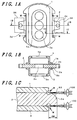
- FIGS. 1A-1C are illustrations of a configuration and welding conditions of a compound electrode for explaining a first embodiment of the present invention.
- FIG. 1A is a plan view of the compound electrode
- FIG. 1B is an cross-sectional view of the compound electrode of FIG. 1A taken along line I B-IB of FIG. 1A
- FIG. 1C is an enlarged fragmentary cross-sectional view of stacked and welded portions of electrode members making up the compound electrode of FIG. 1A taken along line IC - IC of FIG. 1A.
- the same reference numerals as utilized in FIGS. 12A - 12D designate functionally similar parts or portions in FIGS. 1A - 1C.
- FIG. 1A two positions corresponding to a pair of insulator support rods (multiform glasses) 38 are indicated by two-dot chain lines.
- entire edges 2d of the second electrode member 2 are extended outwardly beyond respective edges of the first electrode member 1 and the third electrode member 3 such that sloped portions produced by the shear droop do not form gaps at weld points of the stacked electrode members 1, 2, 3.
- the drooping portion 53 of the second electrode member 2 is extended outwardly and sufficiently to form a protruding portion 2d and prevent formation of a gap between an edge of the first electrode member 1 and the second electrode member 2.
- each of two laser beams L having the same focal length is focused on a corresponding one of the two intended weld points, and thereby both welding of the first and second electrode members 1, 2 and welding of the second and third electrode members 2, 3 are performed with the two laser beams of a required energy, respectively, to provide a required welding strength and no defective welding occurs.
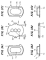
- FIGS. 2A1, 2A2, 2B1, 2B2, 2C1 and 2C2 are plan and side views of the first, second and third electrode members, respectively, constituting the compound electrode of FIGS. 1A - 1C
- the first to third electrode members 1 to 3 are basically similar in shape to the conventional first to third electrode members 1 to 3, respectively, explained in connection with FIGS. 11A1, 11A2, 11B1, 11B2, 11C1 and 11C2, and the same reference numerals as utilized in FIGS. 11A1, 11A2, 11B1, 11B2, 11C1 and 11C2 designate functionally similar parts or portions in FIGS. 2A1, 2A2, 2B1, 2B2, 2C1 and 2C2.
- the first and third electrode members 1, 3 are fabricated from a material of 0.245 mm in thickness, and the second electrode member 2 is fabricated from a material of 0.7 mm in thickness.
- the first, second and third electrode members 1, 2, 3 have the following dimensions in connection with FIGS. 2A1 to 2C2:
- rim portions 1b, 3b of the first and third electrode members 1, 3, respectively, welded to the respective surfaces of the second electrode member 2 by the laser beam, and portions of the edges 2b which are to be welded of the second electrode member 2 are extended outwardly by a distance ⁇ W from conventional positions indicated by two-dot chain lines in FIG. 2B1.
- FIG. 2D is a cross-sectional view of the second electrode member 2 of FIG. 2B1 taken along line IID-IID of FIG. 2B1 for explaining the amount of one example of the shear droop produced at the sheared edge 2b of the second electrode member 2.
- the width K of the shear droop was in a range of from about 0.4 mm to about 1.0 mm
- the amount M of the shear droop was in a range of from about 0.08 mm to about 0.15 mm.
- the edge 2b of the second electrode member 2 is made to extend excessively beyond the rim portions 1b, 3b of the first and third electrode members 1, 3, the protruding portion 2d of the second electrode member 2 blocks such a significant portion of the laser beam for welding the second and third electrode members 2, 3 that sufficient welding is not always achieved, and therefore it is preferable to limit the extension ⁇ W to 0.3 mm.
- the weld points as indicated by "W ⁇ " in FIG. 1A are disposed at positions other than positions corresponding to tabs 2c approximately at centers at the respective long sides of the second electrode member 2 to be embedded into the insulator support rods (multiform glasses) 38.
- the laser beam is focused on predetermined positions to be welded, thereby precision welding is realized, degradation of strength of the welded portions is prevented, the compound electrode is sufficiently integrally assembled, and deterioration of precision due to temperature rise in heat treatment in the manufacturing process and in operation of a cathode ray tube is prevented, and consequently, the present embodiment provides a cathode ray tube capable of a high-quality image display.
- FIGS. 3A1, 3A2, 3B1, 3B2, 3C1 and 3C2 are plan and side views of first, second and third electrode members, respectively, constituting a compound electrode of a second embodiment of the present invention, and the first to third electrode members 1 to 3 are basically similar in shape to the first to third electrode members 1 to 3, respectively, of the first embodiment explained in connection with FIGS. 2A1, 2A2, 2B1, 2B2, 2C1 and 2C2, and the same reference numerals as utilized in FIGS. 2A1, 2A2, 2B1, 2B2, 2C1 and 2C2 designate functionally similar parts or portions in FIGS. 2A1, 2A2, 2B1, 2B2, 2C1 and 2C2.
- ⁇ W a distance from conventional positions as shown in FIG. 3B1 to form a protruding portion 2d.
- the laser beam is focused on predetermined positions to be welded, thereby precision welding is realized, degradation of strength of the welded portions is prevented, the compound electrode is sufficiently integrally assembled, and deterioration of precision in operation of a cathode ray tube is prevented, and consequently, the present embodiment provides a cathode ray tube capable of a high-quality image display.
- FIGS. 4A1, 4A2, 4B1, 4B2, 4C1 and 4C2 are plan and side views of first, second and third electrode members, respectively, constituting a compound electrode of a third embodiment of the present invention, and the first to third electrode members 1 to 3 are basically similar in shape to the conventional first to third electrode members 1 to 3, respectively, explained in connection with FIGS. 11A1, 11A2, 11B1, 11B2, 11C1 and 11C2, and the same reference numerals as utilized in FIGS. 11A1, 11A2, 11B1, 11B2, 11C1 and 11C2 designate functionally similar parts or portions in FIGS. 4A1, 4A2, 4B1, 4B2, 4C1 and 4C2.
- rim portions 1b, 3b of the first and third electrode members 1, 3, respectively, are welded to the respective surfaces of the second electrode member 2 by the laser beam, but the edges 3b of the first electrode member 3 are formed with cutouts 3d at its positions corresponding to weld points.
- the weld points of the third and second electrode members 3, 2 are displaced inwardly from the drooping portions 53 of the second electrode member 2, the weld point of the first and second electrode members 1, 2 and the weld point of the third and second electrode members 3, 2 lie on the same vertical line, and consequently, the first and second electrode members 1, 2 are welded together with high precision under conditions similar to those for welding of the second and third electrode members 2, 3.
- the laser beam is focused on predetermined positions to be welded, thereby precision welding is realized, degradation of strength of the welded portions is prevented, the compound electrode is sufficiently integrally assembled, and deterioration of precision in operation of a cathode ray tube is prevented, and consequently, the present embodiment provides a cathode ray tube capable of a high-quality image display.
- the present invention is not limited to compound electrodes comprised of two cup-shaped electrode members and one plate-like electrode member as explained in the above embodiments, but it is needless to say that the present invention is also applicable to compound electrodes comprised of two cup-shaped electrode members and two or more generally flat electrode members.
- FIG. 5 is a side elevation view of an essential part of an in-line type electron gun viewed in a direction perpendicular to the in-line direction of three electron beams for explaining a color cathode ray tube to which a fourth example of the present invention is applied.
- reference numeral 151 denotes the anode
- 152 is an intermediate electrode
- 153 is a fourth member of a fifth grid electrode
- 154 is a third member of the fifth grid electrode
- 155 is a second member of the fifth grid electrode.
- a compound electrode in accordance with the present invention is used as the intermediate electrode 152.
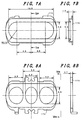
- FIG. 6A is a front view of the side of the intermediate electrode 152 facing the anode 151
- FIG. 6B is a side elevation view of the intermediate electrode 152 of FIG. 6A, taken in the direction of the arrows VIB-VIB thereof
- FIG. 6C is a side elevation view of the intermediate electrode 152 of FIG. 6A, taken in the direction of the arrows VIC-VIC thereof.
- the intermediate electrode 152 comprises a pair of cup-shaped electrode members 173 and a plate-like electrode member 174 sandwiched between the pair of cup-shaped electrode members 173.
- the axial length of the intermediate electrode 152 is 3.5 mm.
- FIG. 7A is a plan view of the cup-shaped electrode member 173 and FIG. 7B is a cross-sectional view of the cup-shaped electrode member 173 taken along line VIIB-VIIB of FIG. 7A.
- the cup-shaped electrode member 173 is formed with a single opening elongated in the in-line direction of the electron beams which is 15 mm in major diameter and 5.8 mm in minor diameter with semicircles of 2.9 mm in radius at the left and right sides.
- the axial length of the cup-shaped electrode member 173 is 1.4 mm.
- the cup-shaped electrode member 173 is fabricated from a material of 0.245 mm in thickness.
- FIG. 8A is a plan view of the plate-like electrode member 174 and FIG. 8B is a side elevation view of the plate-like electrode member 74 of FIG. 8A, taken in the direction of the arrows VIIIB-VIIIB thereof.
- the center electron beam aperture is elliptic
- an inner side portion of the side electron beam apertures is semi-elliptic
- an outer side portion of the side electron beam apertures is semicircular.
- the plate-like electrode member 174 is fabricated from a material of 0.7 mm in thickness.
- ⁇ W by which edges of the plate-like electrode member 174 extend beyond edges of the cup-shaped electrode member 173 in the vicinities of weld points is selected to be 0.05 mm, and the two cup-shaped electrode members 173 and the plate-like electrode member 174 are welded simultaneously at two points axially aligned and spaced by 3.4 mm from the center of the major axis of the plan view of the intermediate electrode 152 as shown in FIG. 6C by using a multiple-beam multiple-spot welding method.
- Opposing end of the third member of the fifth grid electrode 154 and the second member of the fifth grid electrode 155 form a second-stage electrostatic quadrupole lens therebetween.
- Reference numeral 156 denotes a first member of a fifth grid electrode
- 157 is a fourth grid electrode
- 158 is a second member of a third grid electrode
- 159 is a first member of the third grid electrode
- 160 is a second grid electrode
- 161 is a first grid electrode
- 162 are cathodes
- 163 is a stem and 140 are stem pins sealed through the stem 163.
- a pair of insulator support rods 138 have fixed in the predetermined order with predetermined spacings the anode 151, the intermediate electrode 152, the fourth member of the fifth grid electrode 153, the third member of the fifth grid electrode 154, the second member of the fifth grid electrode 155, the first member of the fifth grid electrode 156, the fourth grid electrode 157, the second member of the third grid electrode 158, the first member of the third grid electrode 159, the second grid electrode 160, the first grid electrode 161 and the cathodes 162, and these electrodes are mounted on the stem 163.
- the cathodes 162 and several of the electrodes are supplied with display signals or operating voltages via stem pins 140 sealed through the stem 163.
- Reference numeral 164 denotes the shield cup
- 165 is the internal resistor
- 166 is its anode voltage terminal
- 167 is its intermediate terminal
- 168 is its low voltage terminal.
- the anode 151 is supplied with an anode voltage which is the highest voltage, about 27 kV, for example, and the intermediate electrode 152 is supplied with an intermediate voltage which is 50 to 60 % of the anode voltage via the internal resistor 165.
- the fourth member 153 and the second member 155 of the fifth grid electrode and the second member 158 of the third grid electrode are connected with each other within the cathode ray tube and are supplied with a second focus voltage comprised of a fixed voltage of about 25% of the anode voltage superposed with a dynamic voltage dVf of about 500 to 800 V increasing with increasing deflection of the electron beams.
- the third member 154 and the first member 156 of the fifth grid electrode and the first member 159 of the third grid electrode are internally connected with each other and are supplied with a first focus voltage Vfc of about 28% of the anode voltage Va.
- the fourth grid electrode 157 and the second grid electrode 160 are internally connected with each other and are supplied with a screen voltage VG2 of about 500V to about 800V, and the first grid electrode 161 is supplied with a voltage VG1 in a range of -50 to 0 volts.
- the anode 51, the intermediate electrode 52 and the fourth member 53 of the fifth grid electrode 53 form a main lens thereamong.
- the second-stage electrostatic quadrupole lens is formed between facing portions of the third member 54 and the second member 55 of the fifth grid electrode such that the vertically strong focusing action is exerted on the electron beams when the electron beams are not deflected and the strength of the vertically strong focusing action decreases with increasing deflection of the electron beams.
- One correction lens for the curvature of the image field is formed between the facing portions of the fourth member 153 and the third member 154 of the fifth grid electrode and another correction lens for the curvature of the image field is formed between the facing portions of the second member 155 and the first member 156 of the fifth grid electrode such that the focusing strengths of the correction lenses weaken with increasing deflection of the electron beams.
- the first-stage electrostatic quadrupole lens is formed between the facing portions of the second member 58 and the first member 59 of the third grid electrode such that the horizontally strong focusing action is exerted on the electron beams when the electron beams are not deflected and the strength of the horizontally strong focusing action decreases with increasing deflection of the electron beams.
- This structure of the electron gun increases the effective lens diameter of the main lens compared with a conventional electron gun which does not employ any intermediate electrodes such as the intermediate electrode 152 unlike the present invention, and reduces the diameter of the electron beam spots over the entire viewing screen.
- the second-stage electrostatic quadrupole lens which focuses the electron beams strongly in a vertical direction cancels out the astigmatism of the main lens which focuses the electron beams strongly in a horizontal direction and the first-stage electrostatic quadrupole lens which focuses the electron beams strongly in the horizontal direction cancels out the astigmatism of the second grid electrode 60 which focuses the electron beams strongly in the vertical direction, to provide approximately circular electron beam spots.
- the focusing actions of the first-stage and second-stage electrostatic quadrupole lenses weaken and consequently the astigmatism of the main lens which focuses more strongly in a horizontal direction than in a vertical direction cancels out the astigmatism caused by the deflection magnetic fields which focuses more strongly in the vertical direction than in the horizontal direction.
- the focusing action of the correction lens for curvature of the image field and that of the main lens weaken to lengthen the focal length such that focusing of the electron beams are optimized even at the periphery of the viewing screen.
- This effect by the correction lens for curvature of the image field makes possible the reduction of the required magnitude of a dynamic voltage, and suppresses the increase in the dynamic voltage due to the increase in the maximum deflection angle.
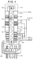
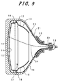
- FIG. 9 is an axial cross-sectional view of an overall structure of a color cathode ray tube as an embodiment of a cathode ray tube employing an electron gun incorporating a compound electrode of the present invention.
- This color cathode ray tube is of the so-called flat panel type, reference numeral 11 denotes a panel portion having a generally flat surface, 12 is a neck portion, 13 is a funnel portion, 14 is a phosphor screen, 15 is a color selection electrode serving as a shadow mask, 16 is a mask frame for supporting the shadow mask 15, 17 are shadow mask suspension mechanisms, 18 are studs embedded in the inner wall of the skirt of the panel portion 11, 19 is a magnetic shield, 20 is an anode button, 21 is an internal conductive coating, 22 is a deflection yoke, 23 is an in-line type electron gun, and 24 are three electron beams (only one of which is shown).
- a vacuum envelope is formed of a panel portion 11, a neck portion 12 and a funnel portion for connecting the panel portion 11 and the neck portion 12, and the junction of the panel portion 11 and the neck portion 12 is wound tightly with a tensioned implosion-prevention band (not shown).
- the phosphor screen (a viewing screen) 14 formed of three-color phosphor elements of red, green and blue coated in stripes or dots.
- the in-line type electron gun 23 housed within the neck portion 12 is comprised of a plurality of electrodes including a compound electrode comprised of a plate-like electrode member and two cup-shaped electrode members welded integrally and having one of the configurations of the above-explained embodiments.
- the in-line type electron gun 23 projects three electron beams 24 in line.
- the shadow mask 15 serving as a color selection electrode has a multiplicity of apertures or a parallel grid array of narrow strips, is closely spaced from the phosphor screen 14 within the panel portion 11 and transmits the three electron beams 24 to the phosphor elements of their intended colors forming the phosphor screen 14 after the three electron beams 24 are deflected horizontally and vertically by the deflection yoke 22.
- the electrodes of the electron gun are arranged with higher precision than in conventional color cathode ray tubes, and thereby accelerating and focusing characteristics do not vary in operation of the color cathode ray tube, good focus is obtained, and consequently this color cathode ray tube displays a high-resolution color image free from variations in performance characteristics due to aging.
- the present invention is not limited to color cathode ray tubes as described above, but is also equally applicable to a direct-view cathode ray tube employing a single beam and other kinds of cathode ray tubes.
- the present invention improves welding accuracy of an electrode fabricated by welding integrally assembled a plurality of electrode members including an electrode member having shear droop at its welding positions and enhances reliability of a cathode ray tube employing an electron gun incorporating such an electrode greatly and provides a high-performance and long-life cathode ray tube.
Landscapes
- Cathode-Ray Tubes And Fluorescent Screens For Display (AREA)
- Manufacture Of Electron Tubes, Discharge Lamp Vessels, Lead-In Wires, And The Like (AREA)
Applications Claiming Priority (2)
| Application Number | Priority Date | Filing Date | Title |
|---|---|---|---|
| JP30816399 | 1999-10-29 | ||
| JP30816399A JP2001126636A (ja) | 1999-10-29 | 1999-10-29 | 陰極線管 |
Publications (1)
| Publication Number | Publication Date |
|---|---|
| EP1096540A1 true EP1096540A1 (de) | 2001-05-02 |
Family
ID=17977666
Family Applications (1)
| Application Number | Title | Priority Date | Filing Date |
|---|---|---|---|
| EP00123351A Withdrawn EP1096540A1 (de) | 1999-10-29 | 2000-10-27 | Kathodenstrahlröhre mit verbesserter Elektrodenanordnung |
Country Status (6)
| Country | Link |
|---|---|
| US (1) | US6476543B1 (de) |
| EP (1) | EP1096540A1 (de) |
| JP (1) | JP2001126636A (de) |
| KR (1) | KR100351081B1 (de) |
| CN (1) | CN1146950C (de) |
| TW (1) | TW483018B (de) |
Cited By (2)
| Publication number | Priority date | Publication date | Assignee | Title |
|---|---|---|---|---|
| US6476543B1 (en) | 1999-10-29 | 2002-11-05 | Hitachi, Ltd. | Cathode ray tube having an improved electrode assembly |
| KR100418935B1 (ko) * | 2002-02-28 | 2004-02-14 | 엘지.필립스디스플레이(주) | 칼라 음극선관용 전자총 |
Families Citing this family (8)
| Publication number | Priority date | Publication date | Assignee | Title |
|---|---|---|---|---|
| JP2001176422A (ja) * | 1999-12-17 | 2001-06-29 | Hitachi Ltd | カラ−陰極線管 |
| KR100494742B1 (ko) * | 2002-02-28 | 2005-06-13 | 엘지.필립스 디스플레이 주식회사 | 칼라음극선관용 전자총 |
| US6847001B2 (en) * | 2002-08-22 | 2005-01-25 | Delphi Technologies, Inc. | Method for metallurgically joining a tube to a member |
| US20040222193A1 (en) * | 2003-05-06 | 2004-11-11 | Venkatasubramanian Ananthanarayanan | Method for resistance welding/brazing a tube to a member |
| US7476824B2 (en) * | 2004-07-07 | 2009-01-13 | Delphi Technologies, Inc. | Welding apparatus for resistance welding heat exchanger tube to tubesheet |
| US7253372B2 (en) * | 2004-07-07 | 2007-08-07 | Delphi Technologies, Inc. | Method for welding heat exchanger tube to tubesheet |
| US20060016788A1 (en) * | 2004-07-23 | 2006-01-26 | Suhre Ryan J | Method for welding employing current |
| CN119381228B (zh) * | 2024-11-12 | 2025-11-28 | 中国科学院空天信息创新研究院 | 带状电子注速调管的阳极和聚焦极的定位装置及装配方法 |
Citations (2)
| Publication number | Priority date | Publication date | Assignee | Title |
|---|---|---|---|---|
| US4827181A (en) * | 1987-03-07 | 1989-05-02 | Samsung Electron Devices Co., Ltd. | Focusing electrodes of an electron gun for use in a color television cathode ray tube |
| US4978886A (en) * | 1987-06-17 | 1990-12-18 | Hitachi, Ltd. | Electron gun for use in color cathode ray tube having a plurality of grid electrodes |
Family Cites Families (7)
| Publication number | Priority date | Publication date | Assignee | Title |
|---|---|---|---|---|
| JP2685467B2 (ja) | 1987-12-25 | 1997-12-03 | 株式会社日立製作所 | カラー受像管用電子銃電極構体 |
| JPH08171870A (ja) | 1994-12-19 | 1996-07-02 | Mitsubishi Electric Corp | 電子銃構体およびその組立方法 |
| JPH10233175A (ja) | 1997-02-17 | 1998-09-02 | Toshiba Electron Eng Corp | カラー陰極線管用電子銃 |
| JPH11135033A (ja) * | 1997-11-04 | 1999-05-21 | Matsushita Electron Corp | カラー受像管 |
| US6255767B1 (en) * | 1997-11-29 | 2001-07-03 | Orion Electric Co., Ltd. | Electrode gun with grid electrode having contoured apertures |
| TW392190B (en) * | 1998-05-11 | 2000-06-01 | Koninkl Philips Electronics Nv | Cathode ray tube comprising an electron gun |
| JP2001126636A (ja) | 1999-10-29 | 2001-05-11 | Hitachi Ltd | 陰極線管 |
-
1999
- 1999-10-29 JP JP30816399A patent/JP2001126636A/ja active Pending
-
2000
- 2000-10-20 TW TW089122133A patent/TW483018B/zh not_active IP Right Cessation
- 2000-10-27 EP EP00123351A patent/EP1096540A1/de not_active Withdrawn
- 2000-10-28 KR KR1020000063728A patent/KR100351081B1/ko not_active Expired - Fee Related
- 2000-10-28 CN CNB001318837A patent/CN1146950C/zh not_active Expired - Fee Related
- 2000-10-30 US US09/698,273 patent/US6476543B1/en not_active Expired - Fee Related
Patent Citations (2)
| Publication number | Priority date | Publication date | Assignee | Title |
|---|---|---|---|---|
| US4827181A (en) * | 1987-03-07 | 1989-05-02 | Samsung Electron Devices Co., Ltd. | Focusing electrodes of an electron gun for use in a color television cathode ray tube |
| US4978886A (en) * | 1987-06-17 | 1990-12-18 | Hitachi, Ltd. | Electron gun for use in color cathode ray tube having a plurality of grid electrodes |
Cited By (2)
| Publication number | Priority date | Publication date | Assignee | Title |
|---|---|---|---|---|
| US6476543B1 (en) | 1999-10-29 | 2002-11-05 | Hitachi, Ltd. | Cathode ray tube having an improved electrode assembly |
| KR100418935B1 (ko) * | 2002-02-28 | 2004-02-14 | 엘지.필립스디스플레이(주) | 칼라 음극선관용 전자총 |
Also Published As
| Publication number | Publication date |
|---|---|
| TW483018B (en) | 2002-04-11 |
| JP2001126636A (ja) | 2001-05-11 |
| KR20010040213A (ko) | 2001-05-15 |
| CN1295337A (zh) | 2001-05-16 |
| KR100351081B1 (ko) | 2002-09-05 |
| CN1146950C (zh) | 2004-04-21 |
| US6476543B1 (en) | 2002-11-05 |
Similar Documents
| Publication | Publication Date | Title |
|---|---|---|
| US5608284A (en) | Color cathode ray tube having a low dynamic focus voltage | |
| EP0126486A1 (de) | Elektronenkanone für Farbbildröhre | |
| US4119884A (en) | Unitized electron gun having electrodes with internal beam-shielding tubes | |
| US6476543B1 (en) | Cathode ray tube having an improved electrode assembly | |
| US6172450B1 (en) | Election gun having specific focusing structure | |
| US4890032A (en) | Color display tube having electrode converging means | |
| US5512797A (en) | Electron guns for color picture tube | |
| US6271625B1 (en) | Picture display device provided with an electron gun, and electron gun for use in such a device | |
| EP0178857B1 (de) | Elektronenkanone | |
| EP0691672A1 (de) | Elektronenkanone für Kathodenstrahlröhren von grossen Abmessungen | |
| JPH05325828A (ja) | 陰極線管 | |
| US4978886A (en) | Electron gun for use in color cathode ray tube having a plurality of grid electrodes | |
| US6744191B2 (en) | Cathode ray tube including an electron gun with specific main lens section | |
| JPH0419660B2 (de) | ||
| US5543681A (en) | In-line type electron guns for color picture tube | |
| US5747922A (en) | Color picture tube and in-line electron gun with focusing electrodes having elongated through holes | |
| US6417610B1 (en) | Color cathode ray tube having improved main lens | |
| US6628061B2 (en) | Electron gun for cathode ray tube | |
| EP0755569B1 (de) | Eine in-line elektronenkanone enthaltende farbkathodenstrahlröhre | |
| US4827181A (en) | Focusing electrodes of an electron gun for use in a color television cathode ray tube | |
| US6586869B1 (en) | Electrodes of electron gun | |
| JP4068261B2 (ja) | 陰極線管用電子銃 | |
| JP3457545B2 (ja) | 陰極線管 | |
| JP2644809B2 (ja) | カラー受像管用電子銃構体 | |
| JP3360863B2 (ja) | 受像管用電子銃 |
Legal Events
| Date | Code | Title | Description |
|---|---|---|---|
| PUAI | Public reference made under article 153(3) epc to a published international application that has entered the european phase |
Free format text: ORIGINAL CODE: 0009012 |
|
| AK | Designated contracting states |
Kind code of ref document: A1 Designated state(s): DE FR GB IT |
|
| AX | Request for extension of the european patent |
Free format text: AL;LT;LV;MK;RO;SI |
|
| 17P | Request for examination filed |
Effective date: 20010903 |
|
| AKX | Designation fees paid |
Free format text: DE FR GB IT |
|
| 17Q | First examination report despatched |
Effective date: 20050318 |
|
| STAA | Information on the status of an ep patent application or granted ep patent |
Free format text: STATUS: THE APPLICATION IS DEEMED TO BE WITHDRAWN |
|
| 18D | Application deemed to be withdrawn |
Effective date: 20050729 |