EP1096348A1 - Intégration d'un appareil de commande sur site dans un système de commande d'une installation - Google Patents
Intégration d'un appareil de commande sur site dans un système de commande d'une installation Download PDFInfo
- Publication number
- EP1096348A1 EP1096348A1 EP99810986A EP99810986A EP1096348A1 EP 1096348 A1 EP1096348 A1 EP 1096348A1 EP 99810986 A EP99810986 A EP 99810986A EP 99810986 A EP99810986 A EP 99810986A EP 1096348 A1 EP1096348 A1 EP 1096348A1
- Authority
- EP
- European Patent Office
- Prior art keywords
- control device
- field control
- functions
- station
- plant
- Prior art date
- Legal status (The legal status is an assumption and is not a legal conclusion. Google has not performed a legal analysis and makes no representation as to the accuracy of the status listed.)
- Granted
Links
- 230000010354 integration Effects 0.000 title claims description 10
- 230000006870 function Effects 0.000 claims abstract description 112
- 238000004891 communication Methods 0.000 claims abstract description 50
- 238000000034 method Methods 0.000 claims description 18
- 238000009434 installation Methods 0.000 claims description 16
- 238000005516 engineering process Methods 0.000 description 7
- 230000003993 interaction Effects 0.000 description 6
- 230000008569 process Effects 0.000 description 5
- 230000008901 benefit Effects 0.000 description 4
- 230000001276 controlling effect Effects 0.000 description 4
- 238000010586 diagram Methods 0.000 description 4
- 230000005540 biological transmission Effects 0.000 description 3
- 230000002452 interceptive effect Effects 0.000 description 3
- XQONXPWVIZZJIL-UHFFFAOYSA-N 1-(4-chlorophenyl)cyclobutane-1-carbonitrile Chemical compound C1=CC(Cl)=CC=C1C1(C#N)CCC1 XQONXPWVIZZJIL-UHFFFAOYSA-N 0.000 description 2
- 230000000007 visual effect Effects 0.000 description 2
- 238000012937 correction Methods 0.000 description 1
- 230000001419 dependent effect Effects 0.000 description 1
- 238000011161 development Methods 0.000 description 1
- 230000014509 gene expression Effects 0.000 description 1
- 230000007246 mechanism Effects 0.000 description 1
- 238000012544 monitoring process Methods 0.000 description 1
- 238000012545 processing Methods 0.000 description 1
- 230000009993 protective function Effects 0.000 description 1
- 230000001105 regulatory effect Effects 0.000 description 1
Images
Classifications
-
- G—PHYSICS
- G05—CONTROLLING; REGULATING
- G05B—CONTROL OR REGULATING SYSTEMS IN GENERAL; FUNCTIONAL ELEMENTS OF SUCH SYSTEMS; MONITORING OR TESTING ARRANGEMENTS FOR SUCH SYSTEMS OR ELEMENTS
- G05B19/00—Programme-control systems
- G05B19/02—Programme-control systems electric
- G05B19/418—Total factory control, i.e. centrally controlling a plurality of machines, e.g. direct or distributed numerical control [DNC], flexible manufacturing systems [FMS], integrated manufacturing systems [IMS] or computer integrated manufacturing [CIM]
- G05B19/4185—Total factory control, i.e. centrally controlling a plurality of machines, e.g. direct or distributed numerical control [DNC], flexible manufacturing systems [FMS], integrated manufacturing systems [IMS] or computer integrated manufacturing [CIM] characterised by the network communication
-
- Y—GENERAL TAGGING OF NEW TECHNOLOGICAL DEVELOPMENTS; GENERAL TAGGING OF CROSS-SECTIONAL TECHNOLOGIES SPANNING OVER SEVERAL SECTIONS OF THE IPC; TECHNICAL SUBJECTS COVERED BY FORMER USPC CROSS-REFERENCE ART COLLECTIONS [XRACs] AND DIGESTS
- Y02—TECHNOLOGIES OR APPLICATIONS FOR MITIGATION OR ADAPTATION AGAINST CLIMATE CHANGE
- Y02P—CLIMATE CHANGE MITIGATION TECHNOLOGIES IN THE PRODUCTION OR PROCESSING OF GOODS
- Y02P90/00—Enabling technologies with a potential contribution to greenhouse gas [GHG] emissions mitigation
- Y02P90/02—Total factory control, e.g. smart factories, flexible manufacturing systems [FMS] or integrated manufacturing systems [IMS]
Definitions
- the invention relates to the field of plant control technology, in particular of plant control technology for high, medium or low voltage switchgear. It relates to a process and a system for integration of a field control device in a plant control system according to the preamble of Claims 1, 10 and 12.
- a system is achieved by a distributed system control system made up of field control devices that Communication buses are interconnected, controlled.
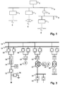
- Figure 1 shows schematically a structure of a plant control system with field control devices 1, an operator station 2, a first and a second communication bus 3.5 and a bus coupler 4.
- the field devices 1 control, regulate, monitor and protect primary devices 6 of the system, which are the actual system purpose fulfill.
- Primary devices 6 are, for example, switches, drives, generators or transformers.
- the bus coupler 4 connects communication buses 3.5, which have different hardware and / or protocol properties have, so that the communication buses 3,4,5 together form a communication network 3,4,5.
- the communication network 3,4,5 transmits messages to control operator station 2 to Field control devices 1 and messages of the field control devices 1 to each other and to the operator station 2, where they are displayed or stored, for example.
- a field control device 1 has at least one program element in the operating station 2 or assigned a function for the transmission of these messages. This function must be known how the communication to the Field control device 1 is to be accomplished. Conversely, the field control device must also 1 be known how to transmit messages to the assigned function are.
- an assigned function transmitted for example a position of a switch which is controlled by the field control device 1, to a visual display within a system diagram and / or an event list and / or an alarm function of the operator station 2.
- each message has a recipient address according to the assignment specify.
- the generated specification data is saved in files, which are each assigned to the field control device 1 and the operator station 2. At a physical installation of a field control device 1 and commissioning In the system, these specification data are stored in bay control unit 1 and in the operator station 2 loaded. This makes the corresponding communication connections created, that is ready for use.
- An advantage of the invention is therefore that there are no detailed logical connections and communication parameters have to be specified by hand, and thus a great deal of engineering effort is eliminated.
- Another The advantage is that a substantial part of the engineering only with the physical Installation and commissioning takes place and that is why it is not a consistent system-wide description of all is required in advance Develop and save communication connections.
- Another The advantage is that an exchange of larger amounts of data between different engineering tools for the configuration of field control devices and the operator station is not necessary. Also are not mechanisms required to maintain the consistency of this data and are errors largely eliminated due to inconsistent data. This reduces the commissioning effort and the quality improves a resulting system control.
- the operating station contains No information about a structure before a physical installation the plant.
- a for example, graphical correspondence or representation of the field control device generated in the operator station. Based on several such correspondences an operator manually creates a representation on the operator station the structure of the facility.
- the operating station contains Information about a structure of the plant, and becomes a field control device during physical installation by an operator manually an element assigned to the plant structure.
- the operating station contains Information about the structure of the facility, which also identifies the Field control devices included. During the physical installation of a field control device This transmits an identification stored in the field control device. Based This identification automatically becomes the right communication connection created according to the structure of the plant.
- Allow the device functions provided by the field control device preferably access to all data related to engineering and needed to configure the field control device within the plant control system become.
- the ones executed on the operator station and a field control device assigned functions are preferably interface functions for Operation of the field control device and for displaying data of the field control device.
- certain standard functions and corresponding logical connections in the operator station automatically installed without a corresponding specification in the Plant structure or by the operator.
- alarm functions and / or event-generating device functions automatically with corresponding alarms.
- generic functions are can be assigned to a field control device, in the operator station before physical installation of a field control device included.
- Such functions are stored in the field controller and variant during the physical installation of the field control device of the operator station transmitted.
- Such functions are in a further advantageous variant and / or device-specific data, such as identification, is not stored in the field controller itself, but is only the field controller assigned an address, for example a URL (Uniform Resource Locator), at which this information is available.
- URL Uniform Resource Locator
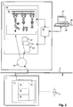
- FIG. 2 schematically shows a structure of a system according to the invention.
- One or more field control devices 1 are connected via a communication network, which consists of one or more communication buses 3, 5 and bus couplers 4 is formed, connected to at least one operator station 2.
- Field control devices 1 are control technology or secondary devices. They are used for control the regulation and protection of a primary device 6.
- Primary devices 6 are devices that perform an actual function of a system, for example Circuit breakers, disconnectors, overhead lines, transformers, generators, Motors, turbines, pumps etc.
- At least one device function 11 is stored on a field control device 1 and executable.
- the device function 11 consists of an external interface 12 for communication with other control technology devices, algorithms 14 for controlling, regulating, monitoring and protecting the primary device 6, and an internal interface 15 for controlling the primary device 6.
- the device function 11 has a functional description 13 on which the device function 11 itself and its parameters describes. This description is preferably in accordance with the draft for the IEC standard 61850-6, or the adopted standard.
- a physical field control device one or several logical field control devices.
- Logical field control devices correspond to this Field control devices 1 as they are understood in the following text.
- the operating station 2 has an engineering application 21 for the integration of Field control devices 1 and for commissioning the system, a system representation 22 with information about a structure and communication links the system, and an input / output unit 25 for display and for manipulating data of the plant representation 22.
- the An input / output unit 25 is provided with a display unit 27, for example one Screen, and an input unit 26, for example a keyboard and / or a pointing device.
- integration takes place of a field control device 1 as follows: At the beginning of an installation of field control devices 1, the plant control system has the communication network 3, 4, 5 and the operator station 2, the plant structure 24 not yet in the operator station 2 is represented. A field control device 1 is connected to the communication network connected. Using a registry service the field control device 1 reports its existence to the communication network in a generally known manner, for example by a Broadcast or multicast: The network provides a logical one Channel available on which each device its presence, its Network address and an identity can send. In a broadcast process all devices connected to the network receive this information, in a multicast process, it receives only a subset of devices, so in the present invention, the operator station 2.
- the operator station 2 sends the Field control device 1 receives a request to transmit the functional description 13 of the device, whereupon the device of operating station 2 describes the function 13 transmitted.
- This description is preferably according to one IEC standard 61850-6 or its draft.
- This standard describes definitions of communication connections for the station control technology. He uses a perspective and terminology according to one "Client / Server" model, in which server services or functions for Make available.
- field control devices 1 in particular are considered as servers, who make their device functions 11 available as services.
- the Device functions 11 enable control of a field control device 1 by another device, for example by a higher-level operator station 2.
- the services or device functions 11 by means of client program elements 23, 23 ', for example on an operating station 2 be executed.
- a call to a service by the control unit 2 corresponds to a logical connection between operator panel 2 and bay control unit 1.
- a logical connection is established described by sender, recipient and type of message or service. Communication parameters of a connection are determined by the data types and data formats are described.
- the engineering application is based on this functional description 13 21 now known which device functions 11 the newly connected bay control device 1 has what logical connections corresponding to these device functions 11 can be built to the field control device 1, and which Communication parameters have these logical connections.
- the engineering application 21 then instantiates one or more assigned functions of the operator station 23.
- These functions of the operator station 23 for example, through program elements, through data structures or through objects in the sense of an object-oriented programming methodology represents.
- the functions of the operator station 23 are for example, "operating a switch”, “reading a status”, “plotting a trend curve of a measured variable "," Entry in an event list ",” Trigger an alarm ", etc. ....
- What types of functions of the operator station 23 one certain device functions 11 can be assigned, for example defined according to the cited standard.
- Preferably all functions or a predefined set of Functions that are assigned to a specific device function 11 can instantiated.
- it is known what type of primary device 6 is assigned to device function 11.
- a software representation this primary device 6, i.e. a primary device presentation is also instantiated in the system representation 22.
- the input / output unit 25 preferably generates one on the display unit 27 graphical representation of the primary device presentations.
- the user uses the input unit 26 to construct the Primary device presentations interactively a graphical representation of the Plant structure.
- the operator needs information where there is a primary device 6 or an associated field control device 1 with a specific identification in the system.
- the resulting one Representation is represented as a system structure 24 on the computer.
- Such a representation is, for example, a single-line diagram as shown in Figure 3 is shown.
- the single-line diagram shows busbars 31, Disconnect switch 32, switch 33, a current transformer 34, voltage transformer 35, generator 36, three-turn transformer 37, motor 38, two-turn transformer 39 and circuit breakers with trolleys (circuit breakers with truck) 40.
- These primary devices are in the graphical representation represented by the symbols shown.
- the illustration shows further graphic elements not shown in FIG. 3, for example for Identifications of primary devices 6, for symbols and identifications for Field control devices 1, and for assignments between primary devices 6 and field control devices 1.
- Certain functions of the operator station 23 are performed by the engineering application 21 automatically with the display due to the type of function the assigned primary device presentation in the system structure 24 linked. Be in operation of the plant after commissioning then for example functions for actuating a switch or functions called to query a state by in the representation of the Plant structure 24 selected the corresponding primary device presentation becomes.
- Operator station 23 functions of the operator station 23 are manual due to their nature and / or data structures determined automatically by the engineering application 21 or assigned to certain graphic elements of the display. For example, the function of the operating station 23, which events received by primary devices 6, summarized so that the events be entered in a common event list. Or it will be several alarm functions combined so that a common Alarm display is controlled.
- the engineering application shares on the basis of the known network address of the field control device 1 21 the functions of the operator station 23 this address with, and notifies the field control device 1 of an address of the assigned functions the operator station 23 with. Addresses are, for example, by fieldbus addresses or through entries in a SCADA database for administration of a SCADA (Supervisory Control and Data Acquisition) system. Through this distribution of addresses, the communication connections between device functions 11 and functions of the operator station 23 configured. The functions configured in this way are in the Field control device 1 or installed in the operator station 2, that is, in one executable form saved.
- field control devices 1 also interactive and graphic, based on a representation of the Functions of the operator station 23, 23 ', specified.
- Such communication between field control devices 1 is, for example, in a switchgear for mutual interlocking of switches required.
- switchgear for certain higher-level functions such as busbar protection own field control devices 1 are provided which do not have any significant interactions have with other field control devices 1. This is in switchgear Interactions between the field control devices 1 low compared to interactions between the field control devices 1 and the operator station 2, so that in addition to the system structure 24, only a little further configuration data is required are.
- control system software required for the system at operator station 2, i.e. the logical connections between device functions 11 with one another as well as functions of the operator station 23 and a graphical user interface, created with minimal manual effort.
- the created Control system software or its functions are used for operation the system installed on operator station 2.
- integration takes place of a field control device 1 as in the first variant, but with the difference that the system structure 24 is already in a computer-readable form is present.
- a primary device presentation that was generated due to a connected field control device 1, one Assign primary device presentation to the system structure 24. This happens for example by a known graphical "drag and drop" assignment.
- the operator needs information on where to go Primary device 6 or an associated field control device 1 with a specific one Identification located in the plant.
- integration takes place a field control device 1 as in the second variant, the plant structure 24 now also identifications of the primary devices 6 and / or the field control devices 1 includes. This makes the assignment to connected devices automated and omitted those described in the first two variants Steps for manual specification of the system structure 24 respectively the assignment of primary device presentations.
- class descriptions of functions of the operator station 23, which serve as a template for an instantiation serve i.e. generic device functions that a bay control device 1 can be assigned in operator station 2 before the physical installation a field control device 1 included.
- such generic device functions are stored in the field control device 1 and are used during the physical installation of the bay control unit 1 transmitted to operator station 2. This has the advantage that the operator station 2 Even less a priori information before installation and commissioning about a system and its devices.
- device-specific device functions 11 and / or data such as for example, an identification is not stored in the field control device itself, but is only an address to the field control device, for example a URL (Uniform Resource Locator). By means of this address these are Information about the communication network or, for example, about a network connected to the communication network, which beyond the system, available.
- the device When operating the system, the device functions 11 and the functions the operating station 23 in accordance with the or at the time of commissioning manually made specifications with each other and with an interactive visual representation of the system structure 24 connected.
- One control and coordination at the plant level is done by the operator station 2 perceived.
- the engineering application 21 is no longer required.
- the engineering application runs another computer than on the operator station 2 used in the company, the two computers via the communication network (3, 4, 5) or another interface communicate with each other.
- a field control device 1 controls several related primary devices. For example, switches, disconnectors and transformers of a panel by a single physical Field control device 1 controlled.
- the field control device 1 has at least one each own device function 11 for each primary device.
Landscapes
- Engineering & Computer Science (AREA)
- General Engineering & Computer Science (AREA)
- Manufacturing & Machinery (AREA)
- Quality & Reliability (AREA)
- Physics & Mathematics (AREA)
- General Physics & Mathematics (AREA)
- Automation & Control Theory (AREA)
- Programmable Controllers (AREA)
- Selective Calling Equipment (AREA)
- Computer And Data Communications (AREA)
- Control By Computers (AREA)
Priority Applications (5)
| Application Number | Priority Date | Filing Date | Title |
|---|---|---|---|
| EP99810986A EP1096348B1 (fr) | 1999-11-01 | 1999-11-01 | Intégration d'un appareil de commande sur site dans un système de commande d'une installation |
| AT99810986T ATE287101T1 (de) | 1999-11-01 | 1999-11-01 | Integration eines feldleitgerätes in ein anlagenleitsystem |
| DE59911450T DE59911450D1 (de) | 1999-11-01 | 1999-11-01 | Integration eines Feldleitgerätes in ein Anlagenleitsystem |
| US09/698,234 US6970771B1 (en) | 1999-11-01 | 2000-10-30 | Integration of a field device in an installation control system |
| JP2000332490A JP2001202104A (ja) | 1999-11-01 | 2000-10-31 | 設備制御システムでのフィールドデバイスの集積化 |
Applications Claiming Priority (1)
| Application Number | Priority Date | Filing Date | Title |
|---|---|---|---|
| EP99810986A EP1096348B1 (fr) | 1999-11-01 | 1999-11-01 | Intégration d'un appareil de commande sur site dans un système de commande d'une installation |
Publications (2)
| Publication Number | Publication Date |
|---|---|
| EP1096348A1 true EP1096348A1 (fr) | 2001-05-02 |
| EP1096348B1 EP1096348B1 (fr) | 2005-01-12 |
Family
ID=8243117
Family Applications (1)
| Application Number | Title | Priority Date | Filing Date |
|---|---|---|---|
| EP99810986A Revoked EP1096348B1 (fr) | 1999-11-01 | 1999-11-01 | Intégration d'un appareil de commande sur site dans un système de commande d'une installation |
Country Status (5)
| Country | Link |
|---|---|
| US (1) | US6970771B1 (fr) |
| EP (1) | EP1096348B1 (fr) |
| JP (1) | JP2001202104A (fr) |
| AT (1) | ATE287101T1 (fr) |
| DE (1) | DE59911450D1 (fr) |
Cited By (10)
| Publication number | Priority date | Publication date | Assignee | Title |
|---|---|---|---|---|
| EP1233318A1 (fr) * | 2001-02-16 | 2002-08-21 | Abb Research Ltd. | Composants de software d'un système de commande décentralisé |
| EP1265118A1 (fr) * | 2001-06-05 | 2002-12-11 | Abb Research Ltd. | Méthode de surveillance de l'installation d'un appareil mobile |
| WO2007110006A1 (fr) * | 2006-03-29 | 2007-10-04 | Siemens Aktiengesellschaft | Appareil de terrain |
| EP1850447A1 (fr) * | 2006-04-24 | 2007-10-31 | Abb Research Ltd. | Inspection de la configuration d'un appareil électronique intelligent |
| WO2008037235A1 (fr) * | 2006-09-28 | 2008-04-03 | Siemens Aktiengesellschaft | Procédé et système pour intégrer un appareil électrique dans un réseau d'alimentation en énergie |
| DE102007048813A1 (de) * | 2007-04-13 | 2008-10-16 | Endress + Hauser Process Solutions Ag | Verfahren zum Bereitstellen einer zuverlässigen Statusinformation für Messwerte in Prozessautomatisierungsanwendungen |
| WO2009087015A2 (fr) * | 2008-01-09 | 2009-07-16 | Endress+Hauser Process Solutions Ag | Procédé d'intégration d'un appareil de terrain dans un réseau relevant de la technique d'automatisation des processus |
| WO2011054618A1 (fr) * | 2009-11-06 | 2011-05-12 | Endress+Hauser Process Solutions Ag | Procédé de mise en oeuvre d'un appareil de terrain utilisé dans un réseau hertzien aux fins d'automatisation |
| WO2011091820A1 (fr) * | 2010-01-29 | 2011-08-04 | Siemens Aktiengesellschaft | Ensemble pour protéger, commander et/ou surveiller une installation de distribution électrique ou d'approvisionnement en énergie électrique |
| WO2012022374A3 (fr) * | 2010-08-17 | 2013-04-18 | Siemens Aktiengesellschaft | Procédé de configuration d'un appareil d'automatisation d'énergie d'une installation d'automatisation d'énergie électrique et ordinateur de configuration pour exécuter le procédé |
Families Citing this family (41)
| Publication number | Priority date | Publication date | Assignee | Title |
|---|---|---|---|---|
| EP1191662B1 (fr) * | 2000-09-21 | 2010-06-16 | ABB Schweiz AG | Configuration d'un système de contrôle d'une installation électrique |
| DE10161072A1 (de) * | 2001-12-12 | 2003-06-18 | Endress & Hauser Gmbh & Co Kg | Feldgeräteelektronik mit einer Sensoreinheit für die Prozessmesstechnik |
| DE10229869A1 (de) * | 2002-07-03 | 2004-01-15 | Siemens Ag | Verfahren zur Auswahl und/oder Fertigung von Automatisierungshardware |
| DE10244845A1 (de) * | 2002-09-20 | 2004-04-08 | Siemens Ag | Anordnung zum Steuern und Überwachen einer Schaltanlage |
| ATE405035T1 (de) * | 2002-11-15 | 2008-08-15 | Abb Research Ltd | Konfigurationssystem für netzwerkgeräte und verfahren zum rekonfigurieren von geräten |
| CN1926541A (zh) * | 2004-03-17 | 2007-03-07 | Abb研究有限公司 | 用于数据一致性验证的设备和方法 |
| WO2008011618A2 (fr) * | 2006-07-21 | 2008-01-24 | Schweitzer Engineering Laboratories, Inc. | Procédé de configuration de dispositifs électroniques intelligents pour faciliter la standardisation de messages de communication parmi plusieurs dei à l'intérieur d'un réseau |
| KR100779019B1 (ko) | 2006-12-14 | 2007-11-22 | 엘에스산전 주식회사 | 변전소 내 지능형 전자장치에서의 데이터 매핑 방법 |
| WO2009055061A1 (fr) | 2007-10-25 | 2009-04-30 | Trilliant Networks, Inc. | Gazomètre ayant un matériau magnétique ultrasensible reconfiguré sur un cadran de compteur et procédé d'utilisation de la reconfiguration du compteur |
| CN101150460A (zh) * | 2007-11-14 | 2008-03-26 | 华为技术有限公司 | 自动调测网络设备的方法及系统 |
| US20090135843A1 (en) | 2007-11-25 | 2009-05-28 | Michel Veillette | System and method for operating mesh devices in multi-tree overlapping mesh networks |
| US8138934B2 (en) | 2007-11-25 | 2012-03-20 | Trilliant Networks, Inc. | System and method for false alert filtering of event messages within a network |
| US8502640B2 (en) * | 2007-11-25 | 2013-08-06 | Trilliant Networks, Inc. | System and method for transmitting and receiving information on a neighborhood area network |
| US8332055B2 (en) | 2007-11-25 | 2012-12-11 | Trilliant Networks, Inc. | Energy use control system and method |
| US8171364B2 (en) | 2007-11-25 | 2012-05-01 | Trilliant Networks, Inc. | System and method for power outage and restoration notification in an advanced metering infrastructure network |
| EP2138913B1 (fr) * | 2008-06-25 | 2011-10-26 | ABB Research Ltd. | Dispositif électronique intelligent flexible |
| EP2321983B1 (fr) | 2008-09-04 | 2018-05-09 | Trilliant Networks, Inc. | Procédé de mise en oeuvre de communications par réseau maillé à l'aide d'un protocole de réseau maillé |
| US8289182B2 (en) | 2008-11-21 | 2012-10-16 | Trilliant Networks, Inc. | Methods and systems for virtual energy management display |
| WO2010059143A1 (fr) * | 2008-11-21 | 2010-05-27 | Trilliant Networks, Inc. | Procédés et systèmes pour un affichage virtuel de gestion d'énergie |
| EP2406778A4 (fr) | 2009-03-11 | 2014-06-25 | Trilliant Networks Inc | Procédé, dispositif et système de mappage de transformateurs à des compteurs et de localisation de pertes de ligne non techniques |
| EP2273644A1 (fr) * | 2009-07-07 | 2011-01-12 | ABB Research Ltd. | Système d'automatisation de sous-station avec fonctions de protection |
| US8155761B2 (en) * | 2009-07-23 | 2012-04-10 | Fisher-Rosemount Systems, Inc. | Process control system with integrated external data sources |
| US8578059B2 (en) * | 2010-02-01 | 2013-11-05 | Invensys Systems, Inc. | Deploying a configuration for multiple field devices |
| JP2011186607A (ja) * | 2010-03-05 | 2011-09-22 | Mitsubishi Electric Corp | フィールドデバイス、フィールドデバイスの設定方法、フィールドデバイス管理装置及びプログラム |
| US9122764B2 (en) | 2010-03-24 | 2015-09-01 | Fisher-Rosemount Systems, Inc. | Methods and apparatus to access process data stored on a server |
| US20110239109A1 (en) * | 2010-03-24 | 2011-09-29 | Mark Nixon | Methods and apparatus to display process data |
| EP2407840A1 (fr) * | 2010-07-16 | 2012-01-18 | Siemens Aktiengesellschaft | Procédé pour faire fonctionner un dispositif d'automatisation |
| WO2012027634A1 (fr) | 2010-08-27 | 2012-03-01 | Trilliant Networkd, Inc. | Système et procédé pour l'opération sans interférence d'émetteurs-récepteurs cositués |
| WO2012037055A1 (fr) | 2010-09-13 | 2012-03-22 | Trilliant Networks | Procédé de détection du vol d'énergie |
| US8717374B2 (en) | 2010-09-13 | 2014-05-06 | Fisher-Rosemount Systems, Inc. | Methods and apparatus to display process control information |
| US9229947B2 (en) | 2010-09-27 | 2016-01-05 | Fisher-Rosemount Systems, Inc. | Methods and apparatus to manage process data |
| WO2012068045A2 (fr) | 2010-11-15 | 2012-05-24 | Trilliant Holdings Inc. | Système et procédé pour une communication sécurisée dans de multiples réseaux à l'aide d'un seul système radioélectrique |
| WO2012097204A1 (fr) | 2011-01-14 | 2012-07-19 | Trilliant Holdings, Inc. | Processus, dispositif et système permettant une optimisation volt/var |
| US9304963B2 (en) * | 2011-01-14 | 2016-04-05 | Rockwell Automation Technologies, Inc. | Data table structure for self-organized management of communication with functional modules coupled via backplane assembly based on received module description including control logic |
| US8970394B2 (en) | 2011-01-25 | 2015-03-03 | Trilliant Holdings Inc. | Aggregated real-time power outages/restoration reporting (RTPOR) in a secure mesh network |
| EP3285459B1 (fr) | 2011-02-10 | 2022-10-26 | Trilliant Holdings, Inc. | Dispositif et procédé pour coordonner des mises à jour de firmware |
| WO2012122310A1 (fr) | 2011-03-08 | 2012-09-13 | Trilliant Networks, Inc. | Système et procédé de gestion de la distribution de charge sur un réseau électrique |
| US9182757B2 (en) | 2011-03-30 | 2015-11-10 | Fisher-Rosemount Systems, Inc. | Methods and apparatus to transmit device description files to a host |
| US9001787B1 (en) | 2011-09-20 | 2015-04-07 | Trilliant Networks Inc. | System and method for implementing handover of a hybrid communications module |
| JP5985198B2 (ja) * | 2012-02-10 | 2016-09-06 | 株式会社東芝 | 変電所自動化システム及び端末の自動認識方法 |
| US10261567B2 (en) | 2013-05-21 | 2019-04-16 | Schweitzer Engineering Laboratories, Inc. | Automatically configurable intelligent electronic device |
Citations (1)
| Publication number | Priority date | Publication date | Assignee | Title |
|---|---|---|---|---|
| DE19624929A1 (de) * | 1996-06-21 | 1998-01-02 | Siemens Ag | Prozeßautomatisierungssystem |
Family Cites Families (23)
| Publication number | Priority date | Publication date | Assignee | Title |
|---|---|---|---|---|
| CA2049618A1 (fr) * | 1991-07-18 | 1993-01-19 | Christopher J. O'brien | Emetteur et controleur integres |
| FR2718543B1 (fr) * | 1994-04-08 | 1996-06-21 | Robot Consult Sa | Système et dispositif de pré-automatisation des installations d'un bâtiment. |
| US6377874B1 (en) * | 1994-09-07 | 2002-04-23 | Spd Technologies Inc. | Power distribution system including integrated power node control center |
| US5793963A (en) * | 1994-10-24 | 1998-08-11 | Fisher Rosemount Systems, Inc. | Apparatus for providing non-redundant secondary access to field devices in a distributed control system |
| US5760492A (en) * | 1995-01-17 | 1998-06-02 | Hitachi, Ltd. | Control system for power transmission and distribution system |
| US6094600A (en) * | 1996-02-06 | 2000-07-25 | Fisher-Rosemount Systems, Inc. | System and method for managing a transaction database of records of changes to field device configurations |
| US6301527B1 (en) * | 1996-04-03 | 2001-10-09 | General Electric Company | Utilities communications architecture compliant power management control system |
| US5909368A (en) * | 1996-04-12 | 1999-06-01 | Fisher-Rosemount Systems, Inc. | Process control system using a process control strategy distributed among multiple control elements |
| US6662240B1 (en) * | 1996-05-08 | 2003-12-09 | Ncr Corporation | Automated configuration of computer accessories |
| US20040194101A1 (en) * | 1997-08-21 | 2004-09-30 | Glanzer David A. | Flexible function blocks |
| US5980078A (en) * | 1997-02-14 | 1999-11-09 | Fisher-Rosemount Systems, Inc. | Process control system including automatic sensing and automatic configuration of devices |
| AU9795598A (en) * | 1997-10-13 | 1999-05-03 | Rosemount Inc. | Communication technique for field devices in industrial processes |
| FI114745B (fi) * | 1998-06-01 | 2004-12-15 | Metso Automation Oy | Kenttälaitteiden hallintajärjestelmä |
| JP2000250605A (ja) * | 1999-03-02 | 2000-09-14 | Yokogawa Electric Corp | 分散型制御システム |
| US6633899B1 (en) * | 1999-05-06 | 2003-10-14 | Sun Microsystems, Inc. | Dynamic installation and configuration broker |
| US6615088B1 (en) * | 1999-06-09 | 2003-09-02 | Amx Corporation | System and method of device interface configuration for a control system |
| JP3583317B2 (ja) * | 1999-06-25 | 2004-11-04 | 三菱電機株式会社 | ネットワーク分散デバイス管理装置 |
| US6618764B1 (en) * | 1999-06-25 | 2003-09-09 | Koninklijke Philips Electronics N.V. | Method for enabling interaction between two home networks of different software architectures |
| US6618630B1 (en) * | 1999-07-08 | 2003-09-09 | Fisher-Rosemount Systems, Inc. | User interface that integrates a process control configuration system and a field device management system |
| US6618745B2 (en) * | 1999-09-10 | 2003-09-09 | Fisher Rosemount Systems, Inc. | Linking device in a process control system that allows the formation of a control loop having function blocks in a controller and in field devices |
| US6662241B1 (en) * | 1999-09-17 | 2003-12-09 | Emc Corporation | Apparatus and method for controlling a peripheral device |
| US6449715B1 (en) * | 1999-10-04 | 2002-09-10 | Fisher-Rosemount Systems, Inc. | Process control configuration system for use with a profibus device network |
| US6574681B1 (en) * | 1999-10-21 | 2003-06-03 | H. Philip White | Network platform for field devices |
-
1999
- 1999-11-01 DE DE59911450T patent/DE59911450D1/de not_active Revoked
- 1999-11-01 AT AT99810986T patent/ATE287101T1/de not_active IP Right Cessation
- 1999-11-01 EP EP99810986A patent/EP1096348B1/fr not_active Revoked
-
2000
- 2000-10-30 US US09/698,234 patent/US6970771B1/en not_active Expired - Fee Related
- 2000-10-31 JP JP2000332490A patent/JP2001202104A/ja active Pending
Patent Citations (1)
| Publication number | Priority date | Publication date | Assignee | Title |
|---|---|---|---|---|
| DE19624929A1 (de) * | 1996-06-21 | 1998-01-02 | Siemens Ag | Prozeßautomatisierungssystem |
Non-Patent Citations (1)
| Title |
|---|
| ROESLER H -J: "DER FELDBUS WAECHST ZUM SYSTEMBUS. PROFIBUS-DP IN DER NEUEN SIMATICS7/M7", ELEKTRONIK,DE,FRANZIS VERLAG GMBH. MUNCHEN, vol. 44, no. 21, 20 October 1995 (1995-10-20), pages 52,54,61 - 66, XP000536319, ISSN: 0013-5658 * |
Cited By (17)
| Publication number | Priority date | Publication date | Assignee | Title |
|---|---|---|---|---|
| EP1233318A1 (fr) * | 2001-02-16 | 2002-08-21 | Abb Research Ltd. | Composants de software d'un système de commande décentralisé |
| EP1265118A1 (fr) * | 2001-06-05 | 2002-12-11 | Abb Research Ltd. | Méthode de surveillance de l'installation d'un appareil mobile |
| CN101416129B (zh) * | 2006-03-29 | 2011-09-28 | 西门子公司 | 现场设备 |
| WO2007110006A1 (fr) * | 2006-03-29 | 2007-10-04 | Siemens Aktiengesellschaft | Appareil de terrain |
| US8165841B2 (en) | 2006-04-24 | 2012-04-24 | Abb Research Ltd | Intelligent electronic device configuration inspection |
| WO2007122196A1 (fr) * | 2006-04-24 | 2007-11-01 | Abb Research Ltd | Controle de la configuration d'un dispositif electronique intelligent |
| EP1850447A1 (fr) * | 2006-04-24 | 2007-10-31 | Abb Research Ltd. | Inspection de la configuration d'un appareil électronique intelligent |
| WO2008037235A1 (fr) * | 2006-09-28 | 2008-04-03 | Siemens Aktiengesellschaft | Procédé et système pour intégrer un appareil électrique dans un réseau d'alimentation en énergie |
| DE102007048813A1 (de) * | 2007-04-13 | 2008-10-16 | Endress + Hauser Process Solutions Ag | Verfahren zum Bereitstellen einer zuverlässigen Statusinformation für Messwerte in Prozessautomatisierungsanwendungen |
| DE102007048813B4 (de) * | 2007-04-13 | 2020-07-30 | Endress + Hauser Process Solutions Ag | Verfahren zum Bereitstellen einer zuverlässigen Statusinformation für Messwerte in Prozessautomatisierungsanwendungen |
| WO2009087015A2 (fr) * | 2008-01-09 | 2009-07-16 | Endress+Hauser Process Solutions Ag | Procédé d'intégration d'un appareil de terrain dans un réseau relevant de la technique d'automatisation des processus |
| WO2009087015A3 (fr) * | 2008-01-09 | 2009-10-15 | Endress+Hauser Process Solutions Ag | Procédé d'intégration d'un appareil de terrain dans un réseau relevant de la technique d'automatisation des processus |
| WO2011054618A1 (fr) * | 2009-11-06 | 2011-05-12 | Endress+Hauser Process Solutions Ag | Procédé de mise en oeuvre d'un appareil de terrain utilisé dans un réseau hertzien aux fins d'automatisation |
| US8995915B2 (en) | 2009-11-06 | 2015-03-31 | Endress + Hauser Process Solutions Ag | Method for servicing a field device of automation technology in a radio network |
| WO2011091820A1 (fr) * | 2010-01-29 | 2011-08-04 | Siemens Aktiengesellschaft | Ensemble pour protéger, commander et/ou surveiller une installation de distribution électrique ou d'approvisionnement en énergie électrique |
| CN102742108B (zh) * | 2010-01-29 | 2015-07-01 | 西门子公司 | 用于保护、控制和/或监视电气开关设备或能量供应设备的装置 |
| WO2012022374A3 (fr) * | 2010-08-17 | 2013-04-18 | Siemens Aktiengesellschaft | Procédé de configuration d'un appareil d'automatisation d'énergie d'une installation d'automatisation d'énergie électrique et ordinateur de configuration pour exécuter le procédé |
Also Published As
| Publication number | Publication date |
|---|---|
| EP1096348B1 (fr) | 2005-01-12 |
| US6970771B1 (en) | 2005-11-29 |
| ATE287101T1 (de) | 2005-01-15 |
| DE59911450D1 (de) | 2005-02-17 |
| JP2001202104A (ja) | 2001-07-27 |
Similar Documents
| Publication | Publication Date | Title |
|---|---|---|
| EP1096348B1 (fr) | Intégration d'un appareil de commande sur site dans un système de commande d'une installation | |
| DE10049504B4 (de) | Verfahren und System zur tranparenten Unterstützung von entfernten Eingabe-/Ausgabeeinrichtungen in einem Prozeßsteuersystem | |
| DE69902503T2 (de) | Managementsystem von Feldgeräten | |
| DE69308942T2 (de) | Steuerungseinrichtung mit Übermittlung von Steuerungsstrukturdefinitionen | |
| EP1527554B1 (fr) | Reseau informatique comportant des noeuds informatiques de diagnostic | |
| EP1738236B1 (fr) | Reseau d'automatisation a composantes reseau produisant des messages d'etat | |
| EP1501062A1 (fr) | Procédé et système à interface homme-machine pour l'opération et observation d'une installation technique | |
| EP2598954B1 (fr) | Configuration des liaisons de communication des appareils de terrain d'un équipement d'automatisation de la distribution d'énergie | |
| EP2806319A2 (fr) | Logiciel de configuration et procédé d'élaboration de données de configuration et d'un programme PLC pour un appareil de commande et/ou de protection comportant une commande de stockage programmable pour la technologie de moyenne ou haute tension | |
| EP2684335B1 (fr) | Installation d'automatisation d'énergie et procédé servant à faire fonctionner une installation d'automatisation d'énergie | |
| EP1191662A1 (fr) | Configuration d'un système de contrôle d'une installation électrique | |
| EP3637205A1 (fr) | Déclenchement de l'image sur une station client de l'opérateur | |
| EP1638028A2 (fr) | Génération assistée par ordinateur et gestion de changement pour interfaces utilisateur | |
| DE19614748C2 (de) | Fehlerdiagnose-Verfahren | |
| EP3948446A1 (fr) | Génération et distribution de structures de données de configuration pour des systèmes de commande | |
| EP2274874B1 (fr) | Contrôle de la liaison de communication entre des appareils de terrain | |
| EP3598255B1 (fr) | Système pourvu d'opérateurs serveurs et d'opérateurs clients | |
| EP1286497B1 (fr) | Procédé pour la représentation graphique de l' état de noeuds de réseau dans un réseau surveillé, et système de surveillance et module de programme associé | |
| EP1903530B1 (fr) | Agencement doté d'un appareil sous vide et son procédé de fonctionnement | |
| DE10053665A1 (de) | Prozeß-Leitsystem zur Fern-Überwachung und -Steuerung von verfahrenstechnischen Prozessen über das Internet | |
| EP1690390B1 (fr) | Procede de transmission de donnees via un bus de donnees, et systeme et passerelle permettant la mise en oeuvre dudit procede | |
| EP1051671B1 (fr) | Systeme de transmission de donnees ou d'informations | |
| DE10154262C2 (de) | Verfahren zur Akquisition, Überwachung und/oder Analyse von Betriebsparametern elektrischer Betriebsmittel, insbesondere Schaltanlagen und deren Komponenten, wobei den Betriebsmitteln oder einer Gruppe von Betriebsmitteln Sensoren und mindestens ein Rechner zugeordnet sind und die Betriebsmittel-Rechner über eine Schnittstelle einen Intranet- oder Internetzugang besitzen | |
| EP1096349A1 (fr) | Configuration pour un dispositif de commande d'une installation | |
| EP2560085A1 (fr) | Procédé de configuration d'un dispositif d'affichage pour l'affichage de signalisations d'alerte dynamiques d'un système de commande et de surveillance d'une installation d'automatisation technique |
Legal Events
| Date | Code | Title | Description |
|---|---|---|---|
| PUAI | Public reference made under article 153(3) epc to a published international application that has entered the european phase |
Free format text: ORIGINAL CODE: 0009012 |
|
| AK | Designated contracting states |
Kind code of ref document: A1 Designated state(s): AT BE CH CY DE DK ES FI FR GB GR IE IT LI LU MC NL PT SE |
|
| AX | Request for extension of the european patent |
Free format text: AL;LT;LV;MK;RO;SI |
|
| 17P | Request for examination filed |
Effective date: 20011005 |
|
| AKX | Designation fees paid |
Free format text: AT BE CH CY DE DK ES FI FR GB GR IE IT LI LU MC NL PT SE |
|
| 17Q | First examination report despatched |
Effective date: 20030910 |
|
| GRAP | Despatch of communication of intention to grant a patent |
Free format text: ORIGINAL CODE: EPIDOSNIGR1 |
|
| GRAS | Grant fee paid |
Free format text: ORIGINAL CODE: EPIDOSNIGR3 |
|
| GRAA | (expected) grant |
Free format text: ORIGINAL CODE: 0009210 |
|
| AK | Designated contracting states |
Kind code of ref document: B1 Designated state(s): AT BE CH CY DE DK ES FI FR GB GR IE IT LI LU MC NL PT SE |
|
| PG25 | Lapsed in a contracting state [announced via postgrant information from national office to epo] |
Ref country code: NL Free format text: LAPSE BECAUSE OF FAILURE TO SUBMIT A TRANSLATION OF THE DESCRIPTION OR TO PAY THE FEE WITHIN THE PRESCRIBED TIME-LIMIT Effective date: 20050112 Ref country code: IT Free format text: LAPSE BECAUSE OF FAILURE TO SUBMIT A TRANSLATION OF THE DESCRIPTION OR TO PAY THE FEE WITHIN THE PRESCRIBED TIME-LIMIT;WARNING: LAPSES OF ITALIAN PATENTS WITH EFFECTIVE DATE BEFORE 2007 MAY HAVE OCCURRED AT ANY TIME BEFORE 2007. THE CORRECT EFFECTIVE DATE MAY BE DIFFERENT FROM THE ONE RECORDED. Effective date: 20050112 Ref country code: IE Free format text: LAPSE BECAUSE OF FAILURE TO SUBMIT A TRANSLATION OF THE DESCRIPTION OR TO PAY THE FEE WITHIN THE PRESCRIBED TIME-LIMIT Effective date: 20050112 Ref country code: FI Free format text: LAPSE BECAUSE OF FAILURE TO SUBMIT A TRANSLATION OF THE DESCRIPTION OR TO PAY THE FEE WITHIN THE PRESCRIBED TIME-LIMIT Effective date: 20050112 |
|
| REG | Reference to a national code |
Ref country code: GB Ref legal event code: FG4D Free format text: NOT ENGLISH |
|
| REG | Reference to a national code |
Ref country code: CH Ref legal event code: EP |
|
| REF | Corresponds to: |
Ref document number: 59911450 Country of ref document: DE Date of ref document: 20050217 Kind code of ref document: P |
|
| REG | Reference to a national code |
Ref country code: IE Ref legal event code: FG4D Free format text: GERMAN |
|
| PG25 | Lapsed in a contracting state [announced via postgrant information from national office to epo] |
Ref country code: SE Free format text: LAPSE BECAUSE OF FAILURE TO SUBMIT A TRANSLATION OF THE DESCRIPTION OR TO PAY THE FEE WITHIN THE PRESCRIBED TIME-LIMIT Effective date: 20050412 Ref country code: DK Free format text: LAPSE BECAUSE OF FAILURE TO SUBMIT A TRANSLATION OF THE DESCRIPTION OR TO PAY THE FEE WITHIN THE PRESCRIBED TIME-LIMIT Effective date: 20050412 |
|
| PG25 | Lapsed in a contracting state [announced via postgrant information from national office to epo] |
Ref country code: ES Free format text: LAPSE BECAUSE OF FAILURE TO SUBMIT A TRANSLATION OF THE DESCRIPTION OR TO PAY THE FEE WITHIN THE PRESCRIBED TIME-LIMIT Effective date: 20050423 |
|
| GBT | Gb: translation of ep patent filed (gb section 77(6)(a)/1977) |
Effective date: 20050420 |
|
| NLV1 | Nl: lapsed or annulled due to failure to fulfill the requirements of art. 29p and 29m of the patents act | ||
| REG | Reference to a national code |
Ref country code: IE Ref legal event code: FD4D |
|
| PLBI | Opposition filed |
Free format text: ORIGINAL CODE: 0009260 |
|
| PG25 | Lapsed in a contracting state [announced via postgrant information from national office to epo] |
Ref country code: CY Free format text: LAPSE BECAUSE OF FAILURE TO SUBMIT A TRANSLATION OF THE DESCRIPTION OR TO PAY THE FEE WITHIN THE PRESCRIBED TIME-LIMIT Effective date: 20051101 Ref country code: AT Free format text: LAPSE BECAUSE OF NON-PAYMENT OF DUE FEES Effective date: 20051101 |
|
| PLAX | Notice of opposition and request to file observation + time limit sent |
Free format text: ORIGINAL CODE: EPIDOSNOBS2 |
|
| PG25 | Lapsed in a contracting state [announced via postgrant information from national office to epo] |
Ref country code: MC Free format text: LAPSE BECAUSE OF NON-PAYMENT OF DUE FEES Effective date: 20051130 Ref country code: LU Free format text: LAPSE BECAUSE OF NON-PAYMENT OF DUE FEES Effective date: 20051130 Ref country code: LI Free format text: LAPSE BECAUSE OF NON-PAYMENT OF DUE FEES Effective date: 20051130 Ref country code: CH Free format text: LAPSE BECAUSE OF NON-PAYMENT OF DUE FEES Effective date: 20051130 Ref country code: BE Free format text: LAPSE BECAUSE OF NON-PAYMENT OF DUE FEES Effective date: 20051130 |
|
| 26 | Opposition filed |
Opponent name: SIEMENS AKTIENGESELLSCHAFT,BERLIN UND MUENCHEN Effective date: 20051012 |
|
| ET | Fr: translation filed | ||
| PLBB | Reply of patent proprietor to notice(s) of opposition received |
Free format text: ORIGINAL CODE: EPIDOSNOBS3 |
|
| REG | Reference to a national code |
Ref country code: CH Ref legal event code: PL |
|
| PLAY | Examination report in opposition despatched + time limit |
Free format text: ORIGINAL CODE: EPIDOSNORE2 |
|
| PLBC | Reply to examination report in opposition received |
Free format text: ORIGINAL CODE: EPIDOSNORE3 |
|
| PLAH | Information related to despatch of examination report in opposition + time limit modified |
Free format text: ORIGINAL CODE: EPIDOSCORE2 |
|
| PLAT | Information related to reply to examination report in opposition deleted |
Free format text: ORIGINAL CODE: EPIDOSDORE3 |
|
| BERE | Be: lapsed |
Owner name: ABB RESEARCH LTD. Effective date: 20051130 |
|
| PG25 | Lapsed in a contracting state [announced via postgrant information from national office to epo] |
Ref country code: PT Free format text: LAPSE BECAUSE OF NON-PAYMENT OF DUE FEES Effective date: 20050612 |
|
| PLAH | Information related to despatch of examination report in opposition + time limit modified |
Free format text: ORIGINAL CODE: EPIDOSCORE2 |
|
| PLBC | Reply to examination report in opposition received |
Free format text: ORIGINAL CODE: EPIDOSNORE3 |
|
| PG25 | Lapsed in a contracting state [announced via postgrant information from national office to epo] |
Ref country code: GR Free format text: LAPSE BECAUSE OF NON-PAYMENT OF DUE FEES Effective date: 20050112 |
|
| PLAB | Opposition data, opponent's data or that of the opponent's representative modified |
Free format text: ORIGINAL CODE: 0009299OPPO |
|
| RDAF | Communication despatched that patent is revoked |
Free format text: ORIGINAL CODE: EPIDOSNREV1 |
|
| PGFP | Annual fee paid to national office [announced via postgrant information from national office to epo] |
Ref country code: DE Payment date: 20091120 Year of fee payment: 11 |
|
| PGFP | Annual fee paid to national office [announced via postgrant information from national office to epo] |
Ref country code: GB Payment date: 20091119 Year of fee payment: 11 Ref country code: FR Payment date: 20091201 Year of fee payment: 11 |
|
| RDAG | Patent revoked |
Free format text: ORIGINAL CODE: 0009271 |
|
| STAA | Information on the status of an ep patent application or granted ep patent |
Free format text: STATUS: PATENT REVOKED |
|
| 27W | Patent revoked |
Effective date: 20091007 |