EP1094582A1 - Pièce de jonction et couvercle pour conduite - Google Patents
Pièce de jonction et couvercle pour conduite Download PDFInfo
- Publication number
- EP1094582A1 EP1094582A1 EP00309299A EP00309299A EP1094582A1 EP 1094582 A1 EP1094582 A1 EP 1094582A1 EP 00309299 A EP00309299 A EP 00309299A EP 00309299 A EP00309299 A EP 00309299A EP 1094582 A1 EP1094582 A1 EP 1094582A1
- Authority
- EP
- European Patent Office
- Prior art keywords
- edge
- edges
- conduit
- lid
- edge portion
- Prior art date
- Legal status (The legal status is an assumption and is not a legal conclusion. Google has not performed a legal analysis and makes no representation as to the accuracy of the status listed.)
- Granted
Links
Images


Classifications
-
- H—ELECTRICITY
- H02—GENERATION; CONVERSION OR DISTRIBUTION OF ELECTRIC POWER
- H02G—INSTALLATION OF ELECTRIC CABLES OR LINES, OR OF COMBINED OPTICAL AND ELECTRIC CABLES OR LINES
- H02G3/00—Installations of electric cables or lines or protective tubing therefor in or on buildings, equivalent structures or vehicles
- H02G3/02—Details
- H02G3/04—Protective tubing or conduits, e.g. cable ladders or cable troughs
- H02G3/0406—Details thereof
- H02G3/0418—Covers or lids; Their fastenings
-
- F—MECHANICAL ENGINEERING; LIGHTING; HEATING; WEAPONS; BLASTING
- F16—ENGINEERING ELEMENTS AND UNITS; GENERAL MEASURES FOR PRODUCING AND MAINTAINING EFFECTIVE FUNCTIONING OF MACHINES OR INSTALLATIONS; THERMAL INSULATION IN GENERAL
- F16L—PIPES; JOINTS OR FITTINGS FOR PIPES; SUPPORTS FOR PIPES, CABLES OR PROTECTIVE TUBING; MEANS FOR THERMAL INSULATION IN GENERAL
- F16L3/00—Supports for pipes, cables or protective tubing, e.g. hangers, holders, clamps, cleats, clips, brackets
- F16L3/26—Supports for pipes, cables or protective tubing, e.g. hangers, holders, clamps, cleats, clips, brackets specially adapted for supporting the pipes all along their length, e.g. pipe channels or ducts
-
- F—MECHANICAL ENGINEERING; LIGHTING; HEATING; WEAPONS; BLASTING
- F16—ENGINEERING ELEMENTS AND UNITS; GENERAL MEASURES FOR PRODUCING AND MAINTAINING EFFECTIVE FUNCTIONING OF MACHINES OR INSTALLATIONS; THERMAL INSULATION IN GENERAL
- F16L—PIPES; JOINTS OR FITTINGS FOR PIPES; SUPPORTS FOR PIPES, CABLES OR PROTECTIVE TUBING; MEANS FOR THERMAL INSULATION IN GENERAL
- F16L43/00—Bends; Siphons
- F16L43/001—Bends; Siphons made of metal
- F16L43/003—Bends; Siphons made of metal having a rectangular cross-section
-
- H—ELECTRICITY
- H02—GENERATION; CONVERSION OR DISTRIBUTION OF ELECTRIC POWER
- H02G—INSTALLATION OF ELECTRIC CABLES OR LINES, OR OF COMBINED OPTICAL AND ELECTRIC CABLES OR LINES
- H02G3/00—Installations of electric cables or lines or protective tubing therefor in or on buildings, equivalent structures or vehicles
- H02G3/02—Details
- H02G3/06—Joints for connecting lengths of protective tubing or channels, to each other or to casings, e.g. to distribution boxes; Ensuring electrical continuity in the joint
- H02G3/0608—Joints for connecting non cylindrical conduits, e.g. channels
Definitions
- the present invention relates to conduit junction pieces and to covers for conduits, and relates particularly, but not exclusively, to corner pieces of conduit and their respective covers in the form of lids and cover plates.
- Such conduit includes that used to carry electrical wiring, powdered or granular material, liquids or gases.
- Trunking or conduit systems for electrical wiring are well known, and our earlier Patent Application No GB9702408.7 includes improvements relating to such systems. That application particularly describes a corner piece, for turning a corner in a horizontal plane.
- Conduit systems for electrical wiring are commonly used within the food, beverage and pharmaceutical industries, to protect the said wiring and to maintain surfaces which are easy to clean. It is therefore important that such conduit systems are provided with smooth surfaces which are less inclined to trap dirt and are therefore easy to clean.
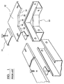
- Figure 1 shows a prior art conduit corner system as described in our Patent Application No GB9702408.7.
- the corner system comprises a corner piece 10, lid 12 and cover plate 14.
- Corner piece 10 cannot be constructed by the simple cutting and bending of a blank cut from a single sheet of material.
- edge portions 16 cannot be formed without producing notches 18 unless additional material is added.
- the acute angle of notches 18 makes them inclined to trap dirt and they therefore represent a hygiene risk to the pharmaceutical, food and beverage industries.
- the cost of cutting and welding into position pieces to fill in notches 18 significantly increases the cost of manufacture.
- Preferred embodiments of the present invention seek to overcome the above disadvantages of the prior art.
- junction piece for connecting at least one first piece of conduit to a second piece of conduit extending at an angle to said first piece, said junction piece comprising:
- junction piece having a first surface and second surfaces extending perpendicularly therefrom with edges of said first surface having no second surfaces extending therefrom , this provides the advantage that junction pieces for conduit can be formed with minimal or no requirement for welding or adhesion.
- the junction piece may be adapted to connect more than two pieces of conduit.
- a cover plate for a joint between the lids of adjacent pieces of conduit comprising: a substantially planar surface, wherein at least one edge thereof is formed from a first length and a second length extending from said first length and non-parallel thereto, and a respective continuous edge portion extending along said first and second lengths and an edge opposite thereto, wherein said edge portions are adapted to engage sides of lids of adjacent pieces of conduit.
- a cover for a junction piece between adjacent lengths of conduit comprising;
- a conduit portion forming a corner piece can be formed from a single sheet of material which is cut and bent with minimal welding or adhesion whilst still providing a cover plate, offering the advantages of easy cleaning and therefore increased hygiene around the joints between the lids of adjacent lengths of conduit.
- the substantially straight third edges of at least one said cover plate may be substantially parallel to each other.
- At least one second edge portion extends only partially along the associated third edge.
- the cover plate By providing the cover plate with edge portions which do not extend entirely along the edge of the first surface, of the lid, to which they are connected, the advantage is provided that the cover plate can be formed from a sheet of material which is simply cut and bent. Ideally the cover plate edge portions which extend entirely along edges are adapted to engage first and further lid edge portions which have no bend at their junction, and on first and further lid edge portions where a bend is formed at their junction, second cover plate edge portions extend only as far as that bend.
- the lid is provided with a gasket, preferably of neoprene, to ensure a secure seal, thereby further reduce the risk to hygiene.
- a conduit corner piece 20 comprises a first planar surface or base 22, having first edges 24, 26, separated by second edges 28. Second planar surfaces or sides 30, 32 extend from first edges 24, 26 in a direction generally perpendicular to the base 22. Sides 30, 32 have third edges 34, 36 respectively.
- the corner piece 20 is formed from a blank as shown in Figure 3. In Figure 3 the dotted lines indicate the lines along which bends are made to create edges 24, 26 and thus form sides 30, 32 perpendicular to base 22. Edges 38 are brought together and welded to form line 39.
- FIG. 2 also shows a lid 40 for conduit corner piece 20.
- the lid 40 comprises a generally planar surface 42 having first edges 44, 46 separated by respective second edges 48. First edges 44,46 have extending from them, in a plane generally perpendicular to said first surface, first edge portions 50, 52. Edge portions 50 of lid 40 are adapted to engage sides 30 of conduit corner piece 20, and edge portion 52 is adapted to engage side 32.
- the conduit corner piece 20 is formed by the bending of a cut sheet material and welding along line 39 where sides 30 meet. The external edge of line 39 is then smoothed and polished so as to form a surface which is more easily cleaned and presents less of a hygiene risk.
- lid 40 is formed by the bending of a sheet of cut metal and along line 54 which joins edge portions 44. Again this weld would be smoothed and polished for reasons of hygiene.
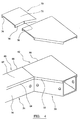
- FIG 4 shows conduit corner piece 20 in use with lid 40 mounted to the corner piece 20.
- the corner piece 20 is also mounted to an elongate conduit portion 56 which comprises base surface (not shown) and parallel side surfaces 56, 58 (shown in Figure 5).
- An elongate lid 60 comprising a generally planar surface 62 and edge portions 64, 66 is mounted to conduit portion 56.
- a cover plate 70 comprising a generally planar surface 72 and edge portions 74, 76 is also provided. Edge portion 76 is angled at 78.
- cover plate 70 is mounted to conduit lids 40, 60, such that cover plate edge portion 74 engages lid edge portions 50, 66 and edge portion 76 engages edge portions 64, 52 such that angled part 78 is located adjacent the junction between edge portions 64, 52.
- Cover plate 70 cannot be constructed by the simple process of cutting and bending a sheet of material and is generally formed by the cutting and bending of a sheet of material and the additional welding into position of at least part of edge portion 76.
- Cover plates 70 and lid 40 may be engaged at assembly by simply spot-welding the two parts together.
- cover plates 70 and lid 40 may be connected at the point of installation, where a turnbuckle (not shown) could be used to engage these parts.
- cover plates 80 are shown mounted to lid 40. Each cover plate 80 comprises a planar surface 82 and edge portions 84, 86. Cover plate 80 in use also engages lids 40, 60. Edge portion 84 is generally straight and extends along the entire edge of surface 82 to which it is attached. Edge portion 84 engages edge portions 66 and 44 of lids 60 and 40 respectively. Edge portion 86 engages edge portion 64 and extends only as far as 88. At point 88, edge portion 86 engages edge portion 52 of lid 40 so as to form a continuous surface therewith.
- Cover plates 80 and lid 40 may be mounted to each other at assembly by simply spot-welding the two parts together. Alternatively, cover plates 80 and lid 40 may be connected at the point of installation, where a turnbuckle 90 could be used to fasten these parts together.
- edge portion 86 may extend along edge portion 52 and not edge portion 64 and only engage with edge portion 64 at 88.
Landscapes
- Engineering & Computer Science (AREA)
- General Engineering & Computer Science (AREA)
- Architecture (AREA)
- Civil Engineering (AREA)
- Structural Engineering (AREA)
- Mechanical Engineering (AREA)
- Details Of Indoor Wiring (AREA)
- Laying Of Electric Cables Or Lines Outside (AREA)
- Protection Of Pipes Against Damage, Friction, And Corrosion (AREA)
- Switch Cases, Indication, And Locking (AREA)
- Road Signs Or Road Markings (AREA)
Applications Claiming Priority (2)
| Application Number | Priority Date | Filing Date | Title |
|---|---|---|---|
| GB9924923 | 1999-10-22 | ||
| GB9924923A GB2349513B (en) | 1999-10-22 | 1999-10-22 | A cover plate for a joint between the lids of adjacent pieces of conduit |
Publications (2)
| Publication Number | Publication Date |
|---|---|
| EP1094582A1 true EP1094582A1 (fr) | 2001-04-25 |
| EP1094582B1 EP1094582B1 (fr) | 2010-04-21 |
Family
ID=10863126
Family Applications (1)
| Application Number | Title | Priority Date | Filing Date |
|---|---|---|---|
| EP00309299A Expired - Lifetime EP1094582B1 (fr) | 1999-10-22 | 2000-10-23 | Pièce de jonction et couvercle pour conduite |
Country Status (4)
| Country | Link |
|---|---|
| EP (1) | EP1094582B1 (fr) |
| AT (1) | ATE465539T1 (fr) |
| DE (1) | DE60044230D1 (fr) |
| GB (2) | GB2365633B (fr) |
Cited By (2)
| Publication number | Priority date | Publication date | Assignee | Title |
|---|---|---|---|---|
| CN107104402A (zh) * | 2017-06-17 | 2017-08-29 | 镇江市长江机电设备厂有限公司 | 一种多功能桥架连接机构 |
| CN109473920A (zh) * | 2018-12-18 | 2019-03-15 | 天长市福骏金属制品有限公司 | 一种高强度易拆装无缝搭接桥架 |
Families Citing this family (3)
| Publication number | Priority date | Publication date | Assignee | Title |
|---|---|---|---|---|
| CN103904596A (zh) * | 2014-03-06 | 2014-07-02 | 安徽精工电缆桥架有限公司 | 一种对角两面转动三通盖板 |
| CN104242184A (zh) * | 2014-07-30 | 2014-12-24 | 安徽卓越电力设备有限公司 | 一种电力设备上所用的引线槽 |
| CN105972319A (zh) * | 2016-07-06 | 2016-09-28 | 中科合成油工程股份有限公司 | 一种水平垂直下三通 |
Citations (2)
| Publication number | Priority date | Publication date | Assignee | Title |
|---|---|---|---|---|
| EP0933852A1 (fr) | 1998-02-03 | 1999-08-04 | Aparellaje Electrico, S.A. | Elément de connexion angulairecoudé pour deux longueurs de goulotte pour système de cablage électrique |
| EP0933851A1 (fr) | 1998-02-03 | 1999-08-04 | Aparellaje Electrico, S.A. | Dispositif de connexion de deux longueurs de goulotte pour système de cablage electrique |
Family Cites Families (7)
| Publication number | Priority date | Publication date | Assignee | Title |
|---|---|---|---|---|
| GB1222336A (en) * | 1969-01-22 | 1971-02-10 | Davis Trunking Ltd | Improvements in or relating to trunking for electrical wiring |
| US4349220A (en) * | 1980-08-28 | 1982-09-14 | Square D Company | Raintight wireway |
| GB8725677D0 (en) * | 1987-11-03 | 1987-12-09 | Swifts Of Scarborough Ltd | Cable trays |
| GB9505519D0 (en) * | 1995-03-18 | 1995-05-03 | Thorsman & Co Uk Ltd | Trunking |
| GB2307111B (en) * | 1995-11-11 | 1997-09-10 | Caradon Mk Electric Ltd | Improvements to electrical trunking |
| GB9622477D0 (en) * | 1996-10-29 | 1997-01-08 | Electrix Northern Ltd | Trunking component and the like |
| GB2318916B (en) * | 1996-10-29 | 2000-12-20 | Electrix | Connector fitting for trunking and the like |
-
1999
- 1999-10-22 GB GB0125032A patent/GB2365633B/en not_active Expired - Fee Related
- 1999-10-22 GB GB9924923A patent/GB2349513B/en not_active Expired - Fee Related
-
2000
- 2000-10-23 DE DE60044230T patent/DE60044230D1/de not_active Expired - Lifetime
- 2000-10-23 EP EP00309299A patent/EP1094582B1/fr not_active Expired - Lifetime
- 2000-10-23 AT AT00309299T patent/ATE465539T1/de not_active IP Right Cessation
Patent Citations (2)
| Publication number | Priority date | Publication date | Assignee | Title |
|---|---|---|---|---|
| EP0933852A1 (fr) | 1998-02-03 | 1999-08-04 | Aparellaje Electrico, S.A. | Elément de connexion angulairecoudé pour deux longueurs de goulotte pour système de cablage électrique |
| EP0933851A1 (fr) | 1998-02-03 | 1999-08-04 | Aparellaje Electrico, S.A. | Dispositif de connexion de deux longueurs de goulotte pour système de cablage electrique |
Cited By (3)
| Publication number | Priority date | Publication date | Assignee | Title |
|---|---|---|---|---|
| CN107104402A (zh) * | 2017-06-17 | 2017-08-29 | 镇江市长江机电设备厂有限公司 | 一种多功能桥架连接机构 |
| CN107104402B (zh) * | 2017-06-17 | 2019-03-15 | 镇江市长江机电设备厂有限公司 | 一种多功能桥架连接机构 |
| CN109473920A (zh) * | 2018-12-18 | 2019-03-15 | 天长市福骏金属制品有限公司 | 一种高强度易拆装无缝搭接桥架 |
Also Published As
| Publication number | Publication date |
|---|---|
| EP1094582B1 (fr) | 2010-04-21 |
| ATE465539T1 (de) | 2010-05-15 |
| DE60044230D1 (de) | 2010-06-02 |
| GB2349513B (en) | 2002-12-18 |
| GB0125032D0 (en) | 2001-12-12 |
| GB2349513A (en) | 2000-11-01 |
| GB2365633B (en) | 2002-12-18 |
| GB9924923D0 (en) | 1999-12-22 |
| GB2365633A (en) | 2002-02-20 |
Similar Documents
| Publication | Publication Date | Title |
|---|---|---|
| JP3337222B2 (ja) | 複合パネルの成形 | |
| EP0521536A1 (fr) | Améliorations aux systèmes de goulottes montantes pour câbles | |
| EP1094582A1 (fr) | Pièce de jonction et couvercle pour conduite | |
| KR20080052677A (ko) | 벤딩된 시트재 및 결합부를 형성하는 방법 | |
| US7004512B2 (en) | Indented apex V-retainer coupling with cushion | |
| US4436518A (en) | Metal trough | |
| KR100423571B1 (ko) | 천장의프레임구조또는그것과유사한지붕관통건축구조물에사용하는박판비막이부재와,그러한부재로구성되는비막이프레임 | |
| EP1102377B1 (fr) | Couvercle pour pièce de jonction de conduit | |
| US4689870A (en) | Method of making honeycomb floor panel | |
| GB2536971A (en) | A coupling device for use in connecting trunking sections | |
| EP0840416B1 (fr) | Composant fermé | |
| HU219106B (hu) | Acéllemez ajtó | |
| EP0840417B1 (fr) | Raccord de connexion pour conduit et analogue | |
| GB2181467A (en) | Elongate sections | |
| EP0053456B1 (fr) | Coffrages perdus en arc | |
| EP0712189A1 (fr) | Système de canalisations composé d'éléments tels que canalisations et éléments de liaison pour branches horizontales et verticales pour câbles, fils ou similaires | |
| EP1597805A1 (fr) | Agregation de liens et elements de raccordement associes | |
| JP3195927B2 (ja) | エルボ用蓋体及びその製造方法 | |
| GB2318917A (en) | Enclosure component | |
| JPH10288387A (ja) | ダクト連結具 | |
| JPH0696974B2 (ja) | マフラーカバー | |
| JPS596990B2 (ja) | 樹脂被覆鋼板製屋根材 | |
| JP3613797B2 (ja) | スライド式カバー | |
| JP2653971B2 (ja) | 屋根板の接合方法 | |
| GB2150619A (en) | An access cover |
Legal Events
| Date | Code | Title | Description |
|---|---|---|---|
| PUAI | Public reference made under article 153(3) epc to a published international application that has entered the european phase |
Free format text: ORIGINAL CODE: 0009012 |
|
| AK | Designated contracting states |
Kind code of ref document: A1 Designated state(s): AT BE CH CY DE DK ES FI FR GB GR IE IT LI LU MC NL PT SE |
|
| AX | Request for extension of the european patent |
Free format text: AL;LT;LV;MK;RO;SI |
|
| 17P | Request for examination filed |
Effective date: 20010929 |
|
| AKX | Designation fees paid |
Free format text: AT BE CH CY DE DK ES FI FR GB GR IE IT LI LU MC NL PT SE |
|
| 17Q | First examination report despatched |
Effective date: 20080826 |
|
| GRAP | Despatch of communication of intention to grant a patent |
Free format text: ORIGINAL CODE: EPIDOSNIGR1 |
|
| GRAS | Grant fee paid |
Free format text: ORIGINAL CODE: EPIDOSNIGR3 |
|
| GRAA | (expected) grant |
Free format text: ORIGINAL CODE: 0009210 |
|
| AK | Designated contracting states |
Kind code of ref document: B1 Designated state(s): AT BE CH CY DE DK ES FI FR GB GR IE IT LI LU MC NL PT SE |
|
| REG | Reference to a national code |
Ref country code: GB Ref legal event code: FG4D |
|
| REG | Reference to a national code |
Ref country code: CH Ref legal event code: EP |
|
| REG | Reference to a national code |
Ref country code: IE Ref legal event code: FG4D |
|
| REF | Corresponds to: |
Ref document number: 60044230 Country of ref document: DE Date of ref document: 20100602 Kind code of ref document: P |
|
| REG | Reference to a national code |
Ref country code: NL Ref legal event code: VDEP Effective date: 20100421 |
|
| PG25 | Lapsed in a contracting state [announced via postgrant information from national office to epo] |
Ref country code: SE Free format text: LAPSE BECAUSE OF FAILURE TO SUBMIT A TRANSLATION OF THE DESCRIPTION OR TO PAY THE FEE WITHIN THE PRESCRIBED TIME-LIMIT Effective date: 20100421 Ref country code: ES Free format text: LAPSE BECAUSE OF FAILURE TO SUBMIT A TRANSLATION OF THE DESCRIPTION OR TO PAY THE FEE WITHIN THE PRESCRIBED TIME-LIMIT Effective date: 20100801 Ref country code: NL Free format text: LAPSE BECAUSE OF FAILURE TO SUBMIT A TRANSLATION OF THE DESCRIPTION OR TO PAY THE FEE WITHIN THE PRESCRIBED TIME-LIMIT Effective date: 20100421 |
|
| PG25 | Lapsed in a contracting state [announced via postgrant information from national office to epo] |
Ref country code: FI Free format text: LAPSE BECAUSE OF FAILURE TO SUBMIT A TRANSLATION OF THE DESCRIPTION OR TO PAY THE FEE WITHIN THE PRESCRIBED TIME-LIMIT Effective date: 20100421 Ref country code: AT Free format text: LAPSE BECAUSE OF FAILURE TO SUBMIT A TRANSLATION OF THE DESCRIPTION OR TO PAY THE FEE WITHIN THE PRESCRIBED TIME-LIMIT Effective date: 20100421 |
|
| PG25 | Lapsed in a contracting state [announced via postgrant information from national office to epo] |
Ref country code: GR Free format text: LAPSE BECAUSE OF FAILURE TO SUBMIT A TRANSLATION OF THE DESCRIPTION OR TO PAY THE FEE WITHIN THE PRESCRIBED TIME-LIMIT Effective date: 20100722 Ref country code: CY Free format text: LAPSE BECAUSE OF NON-PAYMENT OF DUE FEES Effective date: 20100421 |
|
| PG25 | Lapsed in a contracting state [announced via postgrant information from national office to epo] |
Ref country code: PT Free format text: LAPSE BECAUSE OF FAILURE TO SUBMIT A TRANSLATION OF THE DESCRIPTION OR TO PAY THE FEE WITHIN THE PRESCRIBED TIME-LIMIT Effective date: 20100823 Ref country code: DK Free format text: LAPSE BECAUSE OF FAILURE TO SUBMIT A TRANSLATION OF THE DESCRIPTION OR TO PAY THE FEE WITHIN THE PRESCRIBED TIME-LIMIT Effective date: 20100421 |
|
| PLBE | No opposition filed within time limit |
Free format text: ORIGINAL CODE: 0009261 |
|
| STAA | Information on the status of an ep patent application or granted ep patent |
Free format text: STATUS: NO OPPOSITION FILED WITHIN TIME LIMIT |
|
| PG25 | Lapsed in a contracting state [announced via postgrant information from national office to epo] |
Ref country code: BE Free format text: LAPSE BECAUSE OF FAILURE TO SUBMIT A TRANSLATION OF THE DESCRIPTION OR TO PAY THE FEE WITHIN THE PRESCRIBED TIME-LIMIT Effective date: 20100421 |
|
| 26N | No opposition filed |
Effective date: 20110124 |
|
| PG25 | Lapsed in a contracting state [announced via postgrant information from national office to epo] |
Ref country code: IT Free format text: LAPSE BECAUSE OF FAILURE TO SUBMIT A TRANSLATION OF THE DESCRIPTION OR TO PAY THE FEE WITHIN THE PRESCRIBED TIME-LIMIT Effective date: 20100421 |
|
| PG25 | Lapsed in a contracting state [announced via postgrant information from national office to epo] |
Ref country code: MC Free format text: LAPSE BECAUSE OF NON-PAYMENT OF DUE FEES Effective date: 20101031 |
|
| REG | Reference to a national code |
Ref country code: CH Ref legal event code: PL |
|
| PG25 | Lapsed in a contracting state [announced via postgrant information from national office to epo] |
Ref country code: LI Free format text: LAPSE BECAUSE OF NON-PAYMENT OF DUE FEES Effective date: 20101031 Ref country code: FR Free format text: LAPSE BECAUSE OF NON-PAYMENT OF DUE FEES Effective date: 20101102 Ref country code: CH Free format text: LAPSE BECAUSE OF NON-PAYMENT OF DUE FEES Effective date: 20101031 |
|
| REG | Reference to a national code |
Ref country code: FR Ref legal event code: ST Effective date: 20110630 |
|
| REG | Reference to a national code |
Ref country code: DE Ref legal event code: R119 Ref document number: 60044230 Country of ref document: DE Effective date: 20110502 |
|
| PG25 | Lapsed in a contracting state [announced via postgrant information from national office to epo] |
Ref country code: IE Free format text: LAPSE BECAUSE OF NON-PAYMENT OF DUE FEES Effective date: 20101023 |
|
| PG25 | Lapsed in a contracting state [announced via postgrant information from national office to epo] |
Ref country code: LU Free format text: LAPSE BECAUSE OF NON-PAYMENT OF DUE FEES Effective date: 20101023 |
|
| PG25 | Lapsed in a contracting state [announced via postgrant information from national office to epo] |
Ref country code: DE Free format text: LAPSE BECAUSE OF NON-PAYMENT OF DUE FEES Effective date: 20110502 |
|
| PGFP | Annual fee paid to national office [announced via postgrant information from national office to epo] |
Ref country code: GB Payment date: 20190904 Year of fee payment: 20 |
|
| REG | Reference to a national code |
Ref country code: GB Ref legal event code: PE20 Expiry date: 20201022 |
|
| PG25 | Lapsed in a contracting state [announced via postgrant information from national office to epo] |
Ref country code: GB Free format text: LAPSE BECAUSE OF EXPIRATION OF PROTECTION Effective date: 20201022 |