EP1093680B1 - Adaptiver abtastrate basiert auf der netzfrequenz - Google Patents
Adaptiver abtastrate basiert auf der netzfrequenz Download PDFInfo
- Publication number
- EP1093680B1 EP1093680B1 EP00931905A EP00931905A EP1093680B1 EP 1093680 B1 EP1093680 B1 EP 1093680B1 EP 00931905 A EP00931905 A EP 00931905A EP 00931905 A EP00931905 A EP 00931905A EP 1093680 B1 EP1093680 B1 EP 1093680B1
- Authority
- EP
- European Patent Office
- Prior art keywords
- frequency
- derivative
- maximum
- approximately
- power system
- Prior art date
- Legal status (The legal status is an assumption and is not a legal conclusion. Google has not performed a legal analysis and makes no representation as to the accuracy of the status listed.)
- Expired - Lifetime
Links
Images


Classifications
-
- H—ELECTRICITY
- H02—GENERATION; CONVERSION OR DISTRIBUTION OF ELECTRIC POWER
- H02H—EMERGENCY PROTECTIVE CIRCUIT ARRANGEMENTS
- H02H3/00—Emergency protective circuit arrangements for automatic disconnection directly responsive to an undesired change from normal electric working condition with or without subsequent reconnection ; integrated protection
- H02H3/46—Emergency protective circuit arrangements for automatic disconnection directly responsive to an undesired change from normal electric working condition with or without subsequent reconnection ; integrated protection responsive to frequency deviations
-
- G—PHYSICS
- G01—MEASURING; TESTING
- G01R—MEASURING ELECTRIC VARIABLES; MEASURING MAGNETIC VARIABLES
- G01R19/00—Arrangements for measuring currents or voltages or for indicating presence or sign thereof
- G01R19/25—Arrangements for measuring currents or voltages or for indicating presence or sign thereof using digital measurement techniques
- G01R19/2506—Arrangements for conditioning or analysing measured signals, e.g. for indicating peak values ; Details concerning sampling, digitizing or waveform capturing
- G01R19/2509—Details concerning sampling, digitizing or waveform capturing
-
- G—PHYSICS
- G01—MEASURING; TESTING
- G01R—MEASURING ELECTRIC VARIABLES; MEASURING MAGNETIC VARIABLES
- G01R19/00—Arrangements for measuring currents or voltages or for indicating presence or sign thereof
- G01R19/25—Arrangements for measuring currents or voltages or for indicating presence or sign thereof using digital measurement techniques
- G01R19/2513—Arrangements for monitoring electric power systems, e.g. power lines or loads; Logging
-
- H—ELECTRICITY
- H02—GENERATION; CONVERSION OR DISTRIBUTION OF ELECTRIC POWER
- H02H—EMERGENCY PROTECTIVE CIRCUIT ARRANGEMENTS
- H02H1/00—Details of emergency protective circuit arrangements
- H02H1/04—Arrangements for preventing response to transient abnormal conditions, e.g. to lightning or to short duration over voltage or oscillations; Damping the influence of dc component by short circuits in ac networks
-
- H—ELECTRICITY
- H02—GENERATION; CONVERSION OR DISTRIBUTION OF ELECTRIC POWER
- H02H—EMERGENCY PROTECTIVE CIRCUIT ARRANGEMENTS
- H02H3/00—Emergency protective circuit arrangements for automatic disconnection directly responsive to an undesired change from normal electric working condition with or without subsequent reconnection ; integrated protection
- H02H3/44—Emergency protective circuit arrangements for automatic disconnection directly responsive to an undesired change from normal electric working condition with or without subsequent reconnection ; integrated protection responsive to the rate of change of electrical quantities
Definitions
- the present invention generally relates to the synchronization of sampling rates and system frequency for the analysis of system parameters. More particularly, the present invention relates to synchronizing the sampling rate of an electrical power distribution system to the frequency of the power system.
- Protection devices for power systems and equipment typically operate according to protection algorithms based on Fourier analysis of sampled currents and voltages.
- One possible protection scheme captures instantaneous values, or samples, of power system currents and voltages 64 times per power system cycle, and performs a short term Fourier transform (STFT) on the samples. The calculations are updated in real time every 8 sample periods.
- STFT short term Fourier transform
- the accuracy of the Fourier algorithm is closely related to the degree of synchronization between the sampling rate and the power system frequency.
- the frequency of the power system is dynamic. For example, under normal load conditions, the frequency of the power system can deviate from a nominal value (e.g., 60Hz in North America, 50Hz in Europe and elsewhere) by up to 1 Hz. Under severe overload conditions, when protection is critical, the frequency can drop below nominal by as much as 10Hz in as little as one second. Upon generator startup, the frequency can ramp up from 0Hz to the nominal value in less than three seconds. During sudden load rejection, the frequency can overshoot the nominal value by as much as 1.5 times the nominal value. To maintain the accuracy of the Fourier transform calculations, and therefore the reliability of the protection, it is highly desirable to adjust the sampling rate.
- Known techniques for adjusting power system sampling rates rely on generating a filtered and squared version of a power system voltage signal, measuring the frequency by counting the zero crossings of the current and voltage signals, and averaging the number of zero crossings over the number of power system cycles.
- a current reversal i.e., where a substantially sinusoidal curve reverses itself just prior to a zero crossing
- transients and phase shifts can cause "false" zero-crossings.
- the filtering and squaring circuitry for detecting zero-crossings can introduce noise into the signal in the form of jitter, resulting in additional error.
- Another shortcoming of techniques that rely on averaging is that the averaging calculation tends to result in a relatively slow synchronization performance.
- U.S. patents 5,832,414 , 5,832,413 , and 5,721,689 disclose a generator protection system and method for phasor estimation and frequency tracking in digital protection systems.
- the method uses a variable N-point discrete Fourier transform (DFT) to compute phasors based on data acquired from sampled signals.
- DFT discrete Fourier transform
- the change in phasor angle between the current and previous phasor angles is used to estimate the instantaneous frequency of the signal.
- Instantaneous frequencies are averaged over a cycle of the signal to generate an average cycle frequency.
- a number of discrete frequencies and corresponding DFT windows based on a fixed sampling rate and a predetermined fundamental frequency of the signal are defined and used in estimating the instantaneous frequency.
- the DFT window is adjusted by setting it equal to the DFT window corresponding to the discrete frequency closest to the average cycle frequency.
- U.S. Patents 5,671,112 and 5,805,395 disclose systems for implementing accurate V/Hz value measurement and trip time determination for generator/transformer overexcitation protection independent of the conventional frequency tracking and phasor estimation based on DFT techniques.
- a sampled sinusoidal voltage signal is passed through a digital integrator and the magnitude of the integrator output is measured as representative of the V/Hz ratio.
- the digital integrator is implemented in software using a difference equation in a generator protection unit.
- the filter coefficients of the digital integrator are recalculated each time the sampling frequency is changed, and a new value for the peak magnitude of the output of the digital integrator is calculated using the recalculated filter coefficients.
- a non-recursive digital technique which measures the per unit V/Hz value by summing sampled data points every half-cycle of a sinusoidal input signal, and by dividing the sum with an ideal base value sum.
- the disclosed technique approximates the per unit V/Hz value of the input voltage signal without computing voltage and frequency separately.
- the present invention overcomes the problems of the prior art and provides additional advantages, by providing for a technique for adjusting the sampling rate of a power system protection device.
- a method for adapting a sampling rate to the frequency of an electrical power system includes the steps of: performing a first frequency calculation; determining first and second derivatives of the frequency of the electrical power system; determining a normal first derivative, a maximum first derivative value and a maximum second derivative value from power system characteristics; comparing the first and second derivatives to the first and second maximum derivative values, respectively, and comparing the first derivative to the normal first derivative; and if the first derivative is less than the normal first derivative, or if both the first and second derivatives are lower than the first and second maximum derivatives, then accepting the first frequency calculation as true, and adapting the sampling rate based JP 03230722 discloses a protective relay wherein a detection error caused by fluctuation of a power system frequency can be avoided.
- a sampling period is determined in accordance with the present frequency of the power system. Voltages are sampled with the sampling period corresponding to a frequency fluctuation and a vector variation between a sampled value V(t) and a value V(t- ⁇ ) sampled earlier.
- JP 04058714 discloses a digital protective relay device with a frequency correcting device whereby the sampling frequency can become an integer multiple of the current frequency of the power system.
- the frequency correcting device delivers a correcting signal which is proportional to the difference between a reference frequency and the current frequency of the power system.
- the present invention overcomes the problems of the prior art and provides additional advantages, by providing for a technique for adjusting the sampling rate of a power system protection device.
- the present invention provides a method for adapting a sampling rate at which data is sampled in an electrical power system, to the frequency of the electrical power system, comprising the steps of: performing a first frequency calculation to determine the frequency of the electrical power system; determining first and second derivatives of the frequency of the electrical power system; comparing the first and second derivatives to first and second maximum derivative values, respectively, and comparing the first derivative to a normal first derivative; and if the first derivative is less than the normal first derivative, or if both the first and second derivatives are lower than the first and second maximum derivatives, then accepting the first frequency calculation as true, and adapting the sampling rate based on the first frequency calculation, if the frequency of the electrical power system is within a range defined between a minimum frequency (fmin) and a maximum frequency (fmax).
- the present invention further provides a protective relay for providing protective control in a power distribution system, comprising: connection means for connecting the relay to the power distribution system; and processing means for sensing system conditions through the connection means at a sampling frequency, for providing protective control based on system conditions through the connections means, characterised in that the processing means is operable to adjust sampling frequency based on a comparison of an operating frequency and first and second derivatives of the operating frequency of the power distribution system to threshold values, wherein the threshold values include first and second maximum derivative values and a normal first derivative value and maximum and minimum frequency values.
- Techniques implementing the present invention provide greatly improved synchronization, speed, accuracy, and hence protection, over known techniques.
- characteristics of interest are related to changes of the quantity. It will be apparent from the table that the real frequency events are characterized by a relatively slow change in period, or by a relatively fast change in period but having a recognizable trend in one direction (e.g., increasing or decreasing). These characteristics can be used, according to an aspect of the present invention, to distinguish the real frequency events from transients or noise, which can be characterized by relatively fast, erratic (i.e., demonstrating no readily recognizable trend) changes in period.
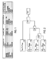
- FIG. 2 a logic diagram representing an exemplary implementation of the present invention is shown.
- a protective relay or other device for the monitoring or protective control of a power system is provided with a microprocessor, programmable logic, circuitry, or other suitable means for performing comparisons of various power system data.
- T n is an n-th period measurement
- f n 1/T n and is an n-th frequency calculation
- df n /dt (f n -f n-1 )/T n
- [(df n /dt)-(df n-1 /dt)]/T n
- maximum frequency values (f min and f max ) are determined for all frequency events; maximum frequency rate values (
- max is determined for all frequency events.
- a logical AND operation is performed to determine if both the n-th frequency rate calculation (
- the result of this first AND operation using conditions 12 and 14 as inputs is then provided as a first input to a logical OR operation, where the other input to the logical OR operation is the comparison of df n /dt to the maximum "normal conditions" frequency rate value (condition 16).
- condition 16 If either condition 16 is true or both of conditions 12 and 14 are true, then n-th frequency calculation f n will be accepted as true (that is, as the correct power system frequency), if f n is within the range of f min -f max (condition 18).
- the other values of interest are based upon power system characteristics. Testing has determined that appropriate values for these parameters are approximately 2-3Hz and 3-5Hz/s 2 , respectively.
- step 100 a first frequency calculation is performed by the protective relay to determine the frequency of the power system.
- step 102 first and second derivatives of the calculated frequency are determined.
- step 104 comparisons to previously-determined threshold values are performed (e.g., by the microprocessor or other suitable comparison circuitry) to determine whether conditions 12, 14, or 16 exist.
- step 106 it is determined whether the first frequency calculation is accepted as valid; that is, whether either condition 16 exists, or whether both conditions 12 and 14 exist, and whether the calculated frequency value is within the predefined range f min -f max . If it is determined in step 106 that the first frequency calculation is valid, then in step 108, the sampling frequency of the protective relay is adjusted as necessary to track the valid first frequency calculation. If it is determined in step 106 that the first frequency calculation is not valid, then the first frequency calculation is not accepted and the process is repeated.
- FIG. 4 depicts the signal space of valid signals representing real frequency events according to the present example.
- signals accepted as representing real frequency events have a frequency within the range of f min -f max , and either have a first derivative (df/dt) less than the threshold value df/dt norm , or have both a first derivative less than the threshold value df/dt max , and a second derivative less than the threshold value
- max the threshold value of valid signals representing real frequency events.
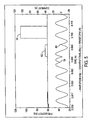
- FIG. 5 frequency plots showing the synchronization of the sampling rate of a protective relay to the power system frequency, using both an embodiment of the present invention and a conventional "averaging" method are provided.
- the power system frequency is represented by a waveform 52
- the performance of the conventional "averaging" method is shown as bold waveform 54
- the performance of the embodiment of the present invention as a lighter-shaded, substantially constant line 56.
- the relay implementing the technique of the present invention provides greatly improved synchronization, and hence greatly improved accuracy of the Fourier transform calculations and greatly improved protective control capabilities of the protective relay.
- current reversals such as those occurring at points 58 and 60, produce inaccuracies in the conventional frequency tracking scheme during time intervals 62 and 64, and that these inaccuracies are substantially reduced by the exemplary technique of the present invention.
- FIG. 6 shows a block diagram of a protective relay capable of implementing the present invention.
- the relay 66 includes connection ports 68 for connection to a power distribution system 70. Through the ports 66, the relay can sense system conditions (e.g., by sampling system data at a data sampling rate), and provide appropriate protective control if and when necessary.
- the relay 66 further includes a suitably-programmed microprocessor 72 which, in addition to performing conventional control functions, also adjusts the sampling frequency to the frequency of the power distribution system according, e.g., to the method described in the connection with FIG. 3 or other suitable method.
- the microprocessor 72 constitutes an exemplary means for carrying out both protective control functions and frequency tracking functions.
Claims (10)
- Verfahren zum Anpassen einer Abtastrate, mit welcher Daten in einem elektrischen Energieversorgungssystem abgetastet werden, an die Frequenz des elektrischen Energieversorgungssystems, wobei das Verfahren gekennzeichnet ist durch die Schritte:Durchführen (100) einer ersten Frequenzberechnung, um die Frequenz des elektrischen Energieversorgungssystems zu bestimmen;Ermitteln (102) erster und zweiter Ableitungen der Frequenz des elektrischen Energieversorgungssystems;Vergleichen (104) der ersten und zweiten Ableitungen mit ersten bzw. zweiten maximalen Ableitungswerten und Vergleichen der ersten Ableitung mit einer normalen ersten Ableitung; undwenn die erste Ableitung kleiner als die normale erste Ableitung ist, oder wenn sowohl die erste als auch zweite Ableitung niedriger als die ersten und zweiten maximalen Ableitungen sind, dann Akzeptieren (106) der ersten Frequenzberechnung als zutreffend und Anpassen (108) der Abtastrate auf der Basis der ersten Frequenzberechnung, wenn die Frequenz des elektrischen Energieversorgungssystems in einem zwischen einer minimalen Frequenz (fmin) und einer maximalen Frequenz (fmax) definierten Bereich liegt.
- Verfahren nach Anspruch 1, wobei die erste maximale Ableitung angenähert 20 Hz/s ist.
- Verfahren nach Anspruch 1 oder 2, wobei die minimale Frequenz (fmin) angenähert 2 Hz ist und die maximale Frequenz (fmax) angenähert 90 Hz ist.
- Verfahren nach einem der vorstehenden Ansprüche, wobei die normale erste Ableitung angenähert 2 Hz/s bis angenähert 3 Hz/s ist.
- Verfahren nach einem der vorstehenden Ansprüche, wobei die maximale zweite Ableitung angenähert 3 Hz/s2 bis angenähert 5 Hz/s2 ist.
- Schutzrelais zur Bereitstellung einer Schutzregelung in einem Energieverteilungssystem, aufweisend:Verbindungsmittel (68) zum Verbinden des Relais mit dem Energieverteilungssystem; undVerarbeitungsmittel (72) zum Messen von Systemzuständen durch die Verbindungsmittel bei einer Abtastfrequenz, um eine Schutzregelung auf der Basis von Systemzuständen durch die Verbindungsmittel bereitzustellen, dadurch gekennzeichnet, dass die Verarbeitungsmittel so betrieben werden können, dass sie die Abtastfrequenz auf der Basis eines Vergleichs einer Betriebsfrequenz und erster und zweiter Ableitungen der Betriebsfrequenz des Energieverteilungssystems mit Schwellenwerten anpassen, wobei die Schwellenwerte maximale erste und zweite Ableitungswerte und einen normalen ersten Ableitungswert und maximale und minimale Frequenzwerte beinhalten, wobei, wenn die erste Ableitung kleiner als die normale erste Ableitung ist, oder wenn sowohl die erste als auch zweite Ableitung niedriger als die ersten und zweiten maximalen Ableitungen sind, dann die Abtastrate auf der Basis der ersten Frequenzberechnung angepasst wird, wenn die Betriebsfrequenz in einem zwischen den minimalen und maximalen Frequenzwerten definierten Bereich liegt.
- Schutzrelais nach Anspruch 6, wobei die minimale Betriebsfrequenz angenähert 20 Hz/s ist.
- Schutzrelais nach Anspruch 6 oder 7, wobei die minimale Betriebsfrequenz angenähert 2 Hz ist und die maximale Frequenz angenähert 90 Hz ist.
- Schutzrelais nach einem der vorstehenden Ansprüche 6 bis 8, wobei die normale erste Ableitung angenähert 2 Hz/s bis angenähert 3 Hz/s ist.
- Schutzrelais nach einem der vorstehenden Ansprüche 6 bis 9, wobei die maximale zweite Ableitung angenähert 3 Hz/s2 bis angenähert 5 Hz/s2 ist.
Applications Claiming Priority (3)
| Application Number | Priority Date | Filing Date | Title |
|---|---|---|---|
| US305293 | 1999-05-05 | ||
| US09/305,293 US6366864B1 (en) | 1999-05-05 | 1999-05-05 | Adaptive sampling rate based on power system frequency |
| PCT/US2000/006698 WO2000069042A1 (en) | 1999-05-05 | 2000-05-05 | Adaptive sampling rate based on power system frequency |
Publications (2)
| Publication Number | Publication Date |
|---|---|
| EP1093680A1 EP1093680A1 (de) | 2001-04-25 |
| EP1093680B1 true EP1093680B1 (de) | 2010-08-18 |
Family
ID=23180208
Family Applications (1)
| Application Number | Title | Priority Date | Filing Date |
|---|---|---|---|
| EP00931905A Expired - Lifetime EP1093680B1 (de) | 1999-05-05 | 2000-05-05 | Adaptiver abtastrate basiert auf der netzfrequenz |
Country Status (11)
| Country | Link |
|---|---|
| US (1) | US6366864B1 (de) |
| EP (1) | EP1093680B1 (de) |
| JP (1) | JP4204201B2 (de) |
| CN (1) | CN1302465B (de) |
| AU (1) | AU774129B2 (de) |
| BR (1) | BR0006097B1 (de) |
| CA (1) | CA2335814C (de) |
| CZ (1) | CZ200170A3 (de) |
| DE (1) | DE60044837D1 (de) |
| ES (1) | ES2347946T3 (de) |
| WO (1) | WO2000069042A1 (de) |
Families Citing this family (23)
| Publication number | Priority date | Publication date | Assignee | Title |
|---|---|---|---|---|
| AU2003216397A1 (en) * | 2002-02-25 | 2003-09-09 | General Electric Company | Electrical protection system for reliability improvement based on sensitivity analysis |
| US7508886B2 (en) * | 2005-03-29 | 2009-03-24 | Lockheed Martin Corporation | System for generating a digital signal |
| EP1914419B1 (de) * | 2006-10-19 | 2015-09-16 | Siemens Aktiengesellschaft | Windenergieanlage und Verfahren zur Steuerung der Ausgangsleistung einer Windenergieanlage |
| US8140283B2 (en) * | 2008-12-24 | 2012-03-20 | Schweitzer Engineering Laboratories, Inc. | Independent frequency measurement and tracking |
| US8346402B2 (en) * | 2009-05-11 | 2013-01-01 | Schweitzer Engineering Laboratories Inc | Islanding detection in an electrical power delivery system |
| US8476874B2 (en) | 2009-10-13 | 2013-07-02 | Schweitzer Engineering Laboratories, Inc | Systems and methods for synchronized control of electrical power system voltage profiles |
| KR101212214B1 (ko) * | 2011-06-24 | 2012-12-13 | 엘에스산전 주식회사 | 디지털 보호 계전기 및 디지털 보호 계전기의 동작 방법 |
| TWI489124B (zh) | 2012-07-26 | 2015-06-21 | Delta Electronics Inc | 電力資訊的獲取方法 |
| CN103575955B (zh) * | 2012-07-26 | 2016-03-16 | 台达电子工业股份有限公司 | 电力信息的获取方法 |
| US9478378B2 (en) | 2013-01-04 | 2016-10-25 | Schweitzer Engineering Laboratories, Inc. | Preventing out-of-synchronism reclosing between power systems |
| US9306828B2 (en) | 2013-07-12 | 2016-04-05 | Xyratex Technology Limited-A Seagate Company | Method of, and apparatus for, adaptive sampling |
| US10012680B2 (en) | 2014-02-14 | 2018-07-03 | Infineon Technologies Austria Ag | AC input signal detection |
| EP3093943B1 (de) * | 2015-05-13 | 2020-08-26 | ABB Schweiz AG | Verfahren und vorrichtung zur detektion eines vektorsprungs |
| US10312041B2 (en) | 2015-11-20 | 2019-06-04 | Schweitzer Engineering Laboratories, Inc. | Frequency measurement for electric power delivery system |
| DE102016002267B4 (de) * | 2016-02-26 | 2017-09-14 | Gerd Bumiller | Anordnung und Verfahren zur Messung der elektrischen Eigenschaften am Anschlusspunkt eines elektrischen Energieversorgungsnetzes, von daran angeschlossenen Erzeugern, Verbrauchern oder Teilnetzen |
| US10644493B2 (en) | 2017-05-01 | 2020-05-05 | Schweitzer Engineering Laboratories, Inc. | Power system disturbance detection using power and frequency |
| US10312694B2 (en) | 2017-06-23 | 2019-06-04 | Schweitzer Engineering Laboratories, Inc. | Mode-based output synchronization using relays and a common time source |
| CN107453478A (zh) * | 2017-07-10 | 2017-12-08 | 广东电网有限责任公司佛山供电局 | 一种发电机自启动判断方法及装置 |
| CN107656179B (zh) * | 2017-09-21 | 2020-01-03 | 北京国华世纪电子科技有限公司 | 一种串联故障电弧检测系统及方法 |
| US11231449B2 (en) | 2018-09-21 | 2022-01-25 | Schweitzer Engineering Laboratories, Inc. | Frequency sensing systems and methods |
| CN110426583A (zh) * | 2019-08-13 | 2019-11-08 | 南京东博智慧能源研究院有限公司 | 一种智能插座的数据自适应采集方法 |
| CN110702972B (zh) * | 2019-10-08 | 2020-10-23 | 浙江大学 | 一种模拟信号自适应采样方法及装置 |
| US11381084B1 (en) | 2021-10-05 | 2022-07-05 | Schweitzer Engineering Laboratories, Inc. | Frequency measurement for load shedding and accurate magnitude calculation |
Family Cites Families (15)
| Publication number | Priority date | Publication date | Assignee | Title |
|---|---|---|---|---|
| US4015206A (en) * | 1975-12-22 | 1977-03-29 | Gte Lenkurt (Canada) Ltd. | Protective relaying modem receiver |
| US4063549A (en) * | 1975-12-22 | 1977-12-20 | Technicon Instruments Corporation | Ultrasonic method and apparatus for imaging and characterization of bodies |
| US4630228A (en) * | 1982-06-28 | 1986-12-16 | Systron-Donner Corporation | Transmission line analyzer for automatically identifying the severities and locations of multiple mismatches |
| JPS6188575A (ja) | 1984-10-08 | 1986-05-06 | Hitachi Cable Ltd | Ledアレイ |
| JP2694993B2 (ja) * | 1989-02-22 | 1997-12-24 | 株式会社日立製作所 | 電力用信号処理システムおよびディジタル保護リレー装置 |
| JP2969724B2 (ja) * | 1990-02-06 | 1999-11-02 | 株式会社明電舎 | 変化量保護継電器 |
| JPH0458714A (ja) | 1990-06-25 | 1992-02-25 | Mitsubishi Electric Corp | ディジタル保護継電装置 |
| CN2078942U (zh) * | 1990-12-01 | 1991-06-12 | 能源部南京自动化研究所 | 微机型突变量差动继电器 |
| US5224011A (en) * | 1991-04-19 | 1993-06-29 | Gas Research Institute | Multifunction protective relay system |
| JP3230722B2 (ja) | 1994-12-20 | 2001-11-19 | トヨタ自動車株式会社 | スプレーガンのガン先洗浄方法および装置 |
| US5832414A (en) | 1995-12-18 | 1998-11-03 | Abb Power T&D Company Inc. | Generator protection system and method of compensating for errors in phasor estimation due to oscillations in discrete Fourier transform |
| US5832413A (en) | 1995-12-18 | 1998-11-03 | Abb Power T&D Company Inc. | Generator protection system and method for phasor estimation and frequency tracking during frequency ramping |
| US5721689A (en) | 1995-12-18 | 1998-02-24 | Abb Power T&D Company Inc. | System and method for phasor estimation and frequency tracking in digital protection systems |
| US5671112A (en) | 1996-05-13 | 1997-09-23 | Abb Power T&D Company, Inc. | Digital integrator V/Hz relay for generator and transformer over-excitation protection |
| US5805395A (en) | 1996-12-13 | 1998-09-08 | Abb Power T&D Company Inc. | Half-cycle summation V/Hz relay for generator and transformer over-excitation protection |
-
1999
- 1999-05-05 US US09/305,293 patent/US6366864B1/en not_active Expired - Lifetime
-
2000
- 2000-05-05 CA CA2335814A patent/CA2335814C/en not_active Expired - Fee Related
- 2000-05-05 WO PCT/US2000/006698 patent/WO2000069042A1/en active Application Filing
- 2000-05-05 AU AU49713/00A patent/AU774129B2/en not_active Ceased
- 2000-05-05 ES ES00931905T patent/ES2347946T3/es not_active Expired - Lifetime
- 2000-05-05 CN CN008007721A patent/CN1302465B/zh not_active Expired - Fee Related
- 2000-05-05 DE DE60044837T patent/DE60044837D1/de not_active Expired - Lifetime
- 2000-05-05 JP JP2000617534A patent/JP4204201B2/ja not_active Expired - Lifetime
- 2000-05-05 BR BRPI0006097-6A patent/BR0006097B1/pt not_active IP Right Cessation
- 2000-05-05 EP EP00931905A patent/EP1093680B1/de not_active Expired - Lifetime
- 2000-05-05 CZ CZ200170A patent/CZ200170A3/cs unknown
Also Published As
| Publication number | Publication date |
|---|---|
| CA2335814C (en) | 2012-01-10 |
| EP1093680A1 (de) | 2001-04-25 |
| BR0006097A (pt) | 2001-03-20 |
| CA2335814A1 (en) | 2000-11-16 |
| CN1302465B (zh) | 2010-05-26 |
| AU4971300A (en) | 2000-11-21 |
| JP2002544751A (ja) | 2002-12-24 |
| CZ200170A3 (cs) | 2002-01-16 |
| BR0006097B1 (pt) | 2014-03-25 |
| JP4204201B2 (ja) | 2009-01-07 |
| WO2000069042A1 (en) | 2000-11-16 |
| AU774129B2 (en) | 2004-06-17 |
| CN1302465A (zh) | 2001-07-04 |
| DE60044837D1 (de) | 2010-09-30 |
| ES2347946T3 (es) | 2010-11-26 |
| US6366864B1 (en) | 2002-04-02 |
Similar Documents
| Publication | Publication Date | Title |
|---|---|---|
| EP1093680B1 (de) | Adaptiver abtastrate basiert auf der netzfrequenz | |
| US5514978A (en) | Stator turn fault detector for AC motor | |
| US5671112A (en) | Digital integrator V/Hz relay for generator and transformer over-excitation protection | |
| US5805395A (en) | Half-cycle summation V/Hz relay for generator and transformer over-excitation protection | |
| CA2451438C (en) | Delta filter with an adaptive time window for protective relays | |
| US6571182B2 (en) | Method and system for consolidating phase current samples | |
| US6717394B2 (en) | Method and apparatus for determining frequency of an alternating current signal of an electric power system | |
| US6519537B1 (en) | Apparatus providing on-line indication of frequency of an AC electric power system | |
| US6081768A (en) | Digital peak detector | |
| EP0846271A1 (de) | Ortsbestimmung eines monophasenerdungsfehlers in einem energieverteilungsnetz | |
| AU2002345871A1 (en) | Delta filter with an adaptive time window for protective relays | |
| CA2676893A1 (en) | Independent frequency measurement and tracking | |
| US6104182A (en) | Method of deriving a signal indicating an oscillation in an electric power supply system | |
| US6185482B1 (en) | System and method for rms overcurrent backup function | |
| GB2534000A (en) | Threshold transition detector, RMS measurement and filter | |
| Sezi | A new method for measuring power system frequency | |
| US5832413A (en) | Generator protection system and method for phasor estimation and frequency tracking during frequency ramping | |
| WO2005022171A2 (en) | Method and apparatus for measuring impedance of electrical component under high interference conditions | |
| WO2011089421A1 (en) | Apparatus and method for measuring a phasor of an electrical power system signal | |
| JPH07325636A (ja) | 力率自動調整装置および交流電気量のディジタル量変換方法 | |
| KR101997633B1 (ko) | Teo 및 desa를 이용한 자동 동기화 파라미터 측정 장치 | |
| EP0801745B1 (de) | Messverfahren zur bestimmung der amplitude und phase der grundschwingung einer wechselspannung | |
| JP3395457B2 (ja) | 自動同期装置 | |
| EP3715875B1 (de) | Frequenzmessverfahren und frequenzmessvorrichtung | |
| KR100964114B1 (ko) | 페이저 측정 장치 |
Legal Events
| Date | Code | Title | Description |
|---|---|---|---|
| PUAI | Public reference made under article 153(3) epc to a published international application that has entered the european phase |
Free format text: ORIGINAL CODE: 0009012 |
|
| AK | Designated contracting states |
Kind code of ref document: A1 Designated state(s): AT BE CH CY DE DK ES FI FR GB GR IE IT LI LU MC NL PT SE |
|
| AX | Request for extension of the european patent |
Free format text: AL;LT;LV;MK;RO;SI |
|
| 17P | Request for examination filed |
Effective date: 20010516 |
|
| RBV | Designated contracting states (corrected) |
Designated state(s): DE ES FR GB |
|
| 17Q | First examination report despatched |
Effective date: 20081104 |
|
| GRAP | Despatch of communication of intention to grant a patent |
Free format text: ORIGINAL CODE: EPIDOSNIGR1 |
|
| RIC1 | Information provided on ipc code assigned before grant |
Ipc: H02H 7/26 20060101ALI20100212BHEP Ipc: G01R 23/16 20060101ALI20100212BHEP Ipc: G01R 19/25 20060101AFI20100212BHEP |
|
| GRAS | Grant fee paid |
Free format text: ORIGINAL CODE: EPIDOSNIGR3 |
|
| GRAA | (expected) grant |
Free format text: ORIGINAL CODE: 0009210 |
|
| AK | Designated contracting states |
Kind code of ref document: B1 Designated state(s): DE ES FR GB |
|
| REG | Reference to a national code |
Ref country code: GB Ref legal event code: FG4D |
|
| REF | Corresponds to: |
Ref document number: 60044837 Country of ref document: DE Date of ref document: 20100930 Kind code of ref document: P |
|
| PLBE | No opposition filed within time limit |
Free format text: ORIGINAL CODE: 0009261 |
|
| STAA | Information on the status of an ep patent application or granted ep patent |
Free format text: STATUS: NO OPPOSITION FILED WITHIN TIME LIMIT |
|
| 26N | No opposition filed |
Effective date: 20110519 |
|
| REG | Reference to a national code |
Ref country code: DE Ref legal event code: R097 Ref document number: 60044837 Country of ref document: DE Effective date: 20110519 |
|
| REG | Reference to a national code |
Ref country code: FR Ref legal event code: PLFP Year of fee payment: 16 |
|
| PGFP | Annual fee paid to national office [announced via postgrant information from national office to epo] |
Ref country code: DE Payment date: 20150528 Year of fee payment: 16 Ref country code: GB Payment date: 20150527 Year of fee payment: 16 Ref country code: ES Payment date: 20150526 Year of fee payment: 16 |
|
| PGFP | Annual fee paid to national office [announced via postgrant information from national office to epo] |
Ref country code: FR Payment date: 20150519 Year of fee payment: 16 |
|
| REG | Reference to a national code |
Ref country code: DE Ref legal event code: R119 Ref document number: 60044837 Country of ref document: DE |
|
| GBPC | Gb: european patent ceased through non-payment of renewal fee |
Effective date: 20160505 |
|
| REG | Reference to a national code |
Ref country code: FR Ref legal event code: ST Effective date: 20170131 |
|
| PG25 | Lapsed in a contracting state [announced via postgrant information from national office to epo] |
Ref country code: DE Free format text: LAPSE BECAUSE OF NON-PAYMENT OF DUE FEES Effective date: 20161201 Ref country code: FR Free format text: LAPSE BECAUSE OF NON-PAYMENT OF DUE FEES Effective date: 20160531 |
|
| PG25 | Lapsed in a contracting state [announced via postgrant information from national office to epo] |
Ref country code: GB Free format text: LAPSE BECAUSE OF NON-PAYMENT OF DUE FEES Effective date: 20160505 |
|
| PG25 | Lapsed in a contracting state [announced via postgrant information from national office to epo] |
Ref country code: ES Free format text: LAPSE BECAUSE OF NON-PAYMENT OF DUE FEES Effective date: 20160506 |
|
| REG | Reference to a national code |
Ref country code: ES Ref legal event code: FD2A Effective date: 20181129 |