EP1093555B1 - Check valve - Google Patents
Check valve Download PDFInfo
- Publication number
- EP1093555B1 EP1093555B1 EP99931784A EP99931784A EP1093555B1 EP 1093555 B1 EP1093555 B1 EP 1093555B1 EP 99931784 A EP99931784 A EP 99931784A EP 99931784 A EP99931784 A EP 99931784A EP 1093555 B1 EP1093555 B1 EP 1093555B1
- Authority
- EP
- European Patent Office
- Prior art keywords
- valve
- spring
- housing
- valving element
- chamber
- Prior art date
- Legal status (The legal status is an assumption and is not a legal conclusion. Google has not performed a legal analysis and makes no representation as to the accuracy of the status listed.)
- Expired - Lifetime
Links
- 238000007789 sealing Methods 0.000 claims description 27
- 238000003466 welding Methods 0.000 claims description 7
- 238000010276 construction Methods 0.000 claims description 2
- 239000007789 gas Substances 0.000 description 22
- 239000012530 fluid Substances 0.000 description 4
- 239000000356 contaminant Substances 0.000 description 3
- 230000000903 blocking effect Effects 0.000 description 2
- 238000009826 distribution Methods 0.000 description 2
- 230000000717 retained effect Effects 0.000 description 2
- 239000012080 ambient air Substances 0.000 description 1
- 230000001419 dependent effect Effects 0.000 description 1
- 229910000701 elgiloys (Co-Cr-Ni Alloy) Inorganic materials 0.000 description 1
- 238000002386 leaching Methods 0.000 description 1
- 238000004519 manufacturing process Methods 0.000 description 1
- 239000000463 material Substances 0.000 description 1
- 230000013011 mating Effects 0.000 description 1
- 229910001092 metal group alloy Inorganic materials 0.000 description 1
- 239000007769 metal material Substances 0.000 description 1
- 238000011144 upstream manufacturing Methods 0.000 description 1
Images


Classifications
-
- F—MECHANICAL ENGINEERING; LIGHTING; HEATING; WEAPONS; BLASTING
- F16—ENGINEERING ELEMENTS AND UNITS; GENERAL MEASURES FOR PRODUCING AND MAINTAINING EFFECTIVE FUNCTIONING OF MACHINES OR INSTALLATIONS; THERMAL INSULATION IN GENERAL
- F16K—VALVES; TAPS; COCKS; ACTUATING-FLOATS; DEVICES FOR VENTING OR AERATING
- F16K15/00—Check valves
- F16K15/02—Check valves with guided rigid valve members
- F16K15/021—Check valves with guided rigid valve members the valve member being a movable body around which the medium flows when the valve is open
-
- F—MECHANICAL ENGINEERING; LIGHTING; HEATING; WEAPONS; BLASTING
- F16—ENGINEERING ELEMENTS AND UNITS; GENERAL MEASURES FOR PRODUCING AND MAINTAINING EFFECTIVE FUNCTIONING OF MACHINES OR INSTALLATIONS; THERMAL INSULATION IN GENERAL
- F16K—VALVES; TAPS; COCKS; ACTUATING-FLOATS; DEVICES FOR VENTING OR AERATING
- F16K15/00—Check valves
- F16K15/02—Check valves with guided rigid valve members
- F16K15/025—Check valves with guided rigid valve members the valve being loaded by a spring
- F16K15/026—Check valves with guided rigid valve members the valve being loaded by a spring the valve member being a movable body around which the medium flows when the valve is open
-
- F—MECHANICAL ENGINEERING; LIGHTING; HEATING; WEAPONS; BLASTING
- F16—ENGINEERING ELEMENTS AND UNITS; GENERAL MEASURES FOR PRODUCING AND MAINTAINING EFFECTIVE FUNCTIONING OF MACHINES OR INSTALLATIONS; THERMAL INSULATION IN GENERAL
- F16K—VALVES; TAPS; COCKS; ACTUATING-FLOATS; DEVICES FOR VENTING OR AERATING
- F16K2200/00—Details of valves
- F16K2200/30—Spring arrangements
- F16K2200/305—Constructional features of springs
- F16K2200/3051—Generally flat springs
-
- Y—GENERAL TAGGING OF NEW TECHNOLOGICAL DEVELOPMENTS; GENERAL TAGGING OF CROSS-SECTIONAL TECHNOLOGIES SPANNING OVER SEVERAL SECTIONS OF THE IPC; TECHNICAL SUBJECTS COVERED BY FORMER USPC CROSS-REFERENCE ART COLLECTIONS [XRACs] AND DIGESTS
- Y10—TECHNICAL SUBJECTS COVERED BY FORMER USPC
- Y10T—TECHNICAL SUBJECTS COVERED BY FORMER US CLASSIFICATION
- Y10T137/00—Fluid handling
- Y10T137/7722—Line condition change responsive valves
- Y10T137/7837—Direct response valves [i.e., check valve type]
- Y10T137/785—With retarder or dashpot
-
- Y—GENERAL TAGGING OF NEW TECHNOLOGICAL DEVELOPMENTS; GENERAL TAGGING OF CROSS-SECTIONAL TECHNOLOGIES SPANNING OVER SEVERAL SECTIONS OF THE IPC; TECHNICAL SUBJECTS COVERED BY FORMER USPC CROSS-REFERENCE ART COLLECTIONS [XRACs] AND DIGESTS
- Y10—TECHNICAL SUBJECTS COVERED BY FORMER USPC
- Y10T—TECHNICAL SUBJECTS COVERED BY FORMER US CLASSIFICATION
- Y10T137/00—Fluid handling
- Y10T137/7722—Line condition change responsive valves
- Y10T137/7837—Direct response valves [i.e., check valve type]
- Y10T137/7854—In couplings for coaxial conduits, e.g., drill pipe check valves
- Y10T137/7856—Valve seat formed on or carried by a coupling element
-
- Y—GENERAL TAGGING OF NEW TECHNOLOGICAL DEVELOPMENTS; GENERAL TAGGING OF CROSS-SECTIONAL TECHNOLOGIES SPANNING OVER SEVERAL SECTIONS OF THE IPC; TECHNICAL SUBJECTS COVERED BY FORMER USPC CROSS-REFERENCE ART COLLECTIONS [XRACs] AND DIGESTS
- Y10—TECHNICAL SUBJECTS COVERED BY FORMER USPC
- Y10T—TECHNICAL SUBJECTS COVERED BY FORMER US CLASSIFICATION
- Y10T137/00—Fluid handling
- Y10T137/7722—Line condition change responsive valves
- Y10T137/7837—Direct response valves [i.e., check valve type]
- Y10T137/7904—Reciprocating valves
- Y10T137/7922—Spring biased
- Y10T137/7929—Spring coaxial with valve
Definitions
- the subject invention is directed to check valves for use in ultra high purity gas flow environments.
- the prior art check valve includes a valve housing that is formed or machined to define a valve chamber.
- the valve housing further is formed or machined to include an inlet extending from an external location into the valve chamber and an outlet extending from the valve chamber to a second external location. Portions of the valve housing that surround the inlet to the valve chamber are configured to define a valve seat.
- the prior art check valve further includes a valving element that is configured to sealingly engage the valve seat for blocking flow into the valve chamber. On the other hand, the valving element can move away from the valve seat to permit flow from the inlet into the valve chamber.
- the prior art check valve further includes a biasing member that urges the valving element into sealing engagement with the valve seat.
- the prior art check valve assumes a normally closed position.
- the valving element of the prior art check valve will move away from the valve seat and into its open position if forces exerted by fluid pressure in the inlet exceed the forces exerted by the biasing member.
- Prior art check valves often are used in situations where it is necessary to prevent contaminants generated at downstream locations from flowing through an unpressurized line and into an upstream location.
- US 5,727 594 discloses a low actuation pressure unidirectional flow valve comprising a housing including a fluid flow passage extending therethrough which defines first and second sections. Disposed within the housing between the first and second sections is a valve member.
- the valve member comprises an annular ring portion having a disc portion disposed therewithin. Extending between the ring and disc portions are at least two spirally shaped connecting arm portions. The ring, disc and connecting arm portions define at least two side openings.
- the valve member is movable between a closed position wherein the disc portion covers and seals the first section of the flow passage, and an open position wherein the disc portion is separated from the first section and fluid flows from the first section to the second section via the side openings.
- a check valve that avoids generating noise during and after opening.
- check valve that provides secure sealing of the inlet while still permitting a desirably quick opening response.
- the subject invention is directed to a check valve having a valve housing formed from a first housing component and a second housing component
- the first housing component is configured to define an inlet to the valve and a portion of a valve chamber.
- the second housing component is configured to define an outlet from the valve and a portion from the valve chamber.
- the first and second housing components are mateable with one another to define an enclosed valve chamber that communicates only with the inlet to the valve and the outlet from the valve.
- Mating portions of the first housing component and second housing component are configured to telescope with one another, and the end of the outer telescoped housing component are welded to the inner telescoped housing component.
- the weldment securely seals the valve chamber from the ambient environment, while the location of the weldment substantially prevents contaminants from the weldment leaching into the valve chamber.
- Portions of the second housing component may be formed or machined to define a plurality of gas flow channels substantially at an interface region between the valve chamber and the valve outlet.
- the gas flow channels in the second housing component substantially prevent the valving element described below from blocking the valve outlet.
- the check valve of the subject invention further includes a substantially disk-shaped valving element movably disposed in the valve chamber.
- the valving element is configured to sealingly engage the valve seat that surrounds the inlet to the valve chamber for substantially preventing a flow of gas through the valve.
- the valving element may include a sealing face to which a seal ring is mounted for sealing engagement with the valve seat.
- the valving element defines an outer periphery that is dimensioned and/or configured to permit a flow of gas around the valving element when the valving element is spaced from its sealing engagement with the valve seat.
- valve chamber may include a substantially cylindrically generated inner surface
- the valving element may have a cylindrically generated outer surface that is sufficiently smaller than the cylindrically generated inner surface of the valve chamber to permit gas flow therebetween.
- the valve housing and/or the valving element may be configured to define gas flow channels for accommodating a flow of gas when the valving element is spaced from its sealing engagement around the inlet to the valve.
- the check valve of the subject invention further includes a substantially disk-shaped spring extending between the valving element and the valve housing.
- the spring is configured and disposed for urging the valving element toward and into sealing engagement with the valve seat.
- the spring may be a substantially planar disk that is stamped, machined and/or formed to define a plurality of legs extending between portions of the spring that are connected to the valving element and portions of the spring that are connected to the valve housing. Regions of the spring between the legs accommodate a flow of gas from the inlet to the outlet when the valving element is spaced from its sealing engagement with the valve seat.
- the legs of the spring preferably extend in non-radial directions, and may include portions that extend substantially helically. Thus, radial inner and radial outer portions of the spring are easily deflectable relative to one another.
- the legs of the disk-like spring preferably are non-symmetrically spaced around the axis of the spring.
- the spring may include two legs that extend from inner or outer locations on the spring that are spaced from one another by approximately 120°.
- a large arc segment of the spring will exist without legs extending between the valving element and the valve housing.
- This configuration results in an asymmetrical or non-uniform application of forces exerted by the spring between the valve housing and the valving element. These non-uniform forces substantially prevent the generation of a resonant condition in the valving element that would cause a noise-generating flutter in the valving element.
- the valve of the subject invention is substantially quieter than prior art check valves and leads to a substantially improved work environment.
- the non-symmetrical loading achieved by the spring causes one side of the spring to initially lift from sealing engagement from the valve housing. Other parts of the spring then rapidly follow the initial movement of the valving element from sealing engagement. This characteristic is roughly comparable to separating a suction cup from a surface by initially lifting one side of the suction cup rather than pulling the suction cup axially. Consequently, the spring employed in the subject check valve results in a very rapid opening response.
- Central portions of the disk-like spring may be connected to the valving element, and outer portions of the disk-like spring may be connected to the valve housing. More particularly, central portions of the spring may be securely affixed between two components of the valving element that are staked together near the longitudinal axis of the valving element. Similarly, outer portions of the spring may be secured between the first and second housing components.
- This configuration and disposition of the spring relative to the valving element and to the housing components is conducive to the above-described asymmetrical configuration of the spring and the above-referenced advantages thereof. Additionally, this dispositioning of the spring enables the spring to be isolated from the heat of welding, as explained herein.
- the spring urges the valving element into a normally closed position in which the valving element sealingly engages the valve seat.
- Pressurized gas directed into the inlet of the valve housing will exert forces on the sealing face of the valving element.
- Sufficient forces exerted by gases in the inlet will overcome the forces exerted by the spring.
- these gas forces will cause one side of the valving element to lift away from sealing engagement with the valve seat.
- Other portions of the valving element will follow quickly, and the valving element will move away from the inlet and into a fully opened condition.
- the asymmetrical forces exerted by the spring will prevent the establishment of a resonant condition that would cause a rocking or fluttering of the valving element in the chamber and that would generate an objectionable noise.
- the movement of the valving element in the opening direction may extend until the valving element engages portions of the second housing component surrounding the outlet to the valve. However, channels formed in the second housing component prevent a complete blockage of the outlet and ensure a continuous flow of gas between the axially aligned inlet and outlet.
- the spring Upon termination or significant reduction of the gas flow toward the inlet, the spring will urge the valving element back into sealing engagement with the valve housing.
- the asymmetrical configuration of the spring may cause one side of the valving element to contact the valve housing initially. However, remaining portions of the valving element will move quickly into complete sealing engagement with the valve housing.
- a check valve in accordance with the subject invention is identified generally by the numeral 10 in FIGS. 1 and 2.
- the check valve 10 includes a valve housing 12 which is formed from a first housing component 14 and a second housing component 16.
- the first housing component 14, as shown most clearly in FIG. 4, is of generally stepped cylindrical configuration and includes an inlet 18 extending into one longitudinal end 19 and a first chamber recess 20 extending from the inlet 18 to the opposed end 21 of the first housing component 14.
- the first chamber recess 20 includes a valve seat 22 aligned substantially orthogonally to the axis of the inlet 18.
- a first cylindrical chamber wall 24 is generated concentrically with the inlet 18 and defines an inside diameter "a".
- a stop wall 26 extends radially outwards from the end of the first cylindrical chamber wall 24 remote from the valve seat 22. The stop wall 26 will define a limit of engagement of the first and second housing components 14 and 16 as explained further below.
- a cylindrical engagement wall 28 extends from the stop wall 26 to the end 21 of the first housing component 14 opposite the inlet 18.
- the cylindrical engagement wall 28 defines an inside diameter "b" which exceeds the inside diameter "a” of the cylindrical chamber wall 24.
- the second housing component 16 also is of generally stepped cylindrical configuration, as shown in FIGS. 5 and 6, and includes a second chamber recess 30 defined by a cylindrical chamber wall 32.
- the cylindrical chamber wall 32 has an annular end face 34 that is substantially planar and aligned substantially orthogonally to the axis of the second housing component 16.
- the cylindrical chamber wall 32 defines an inside diameter "a" substantially equal to the inside diameter "a" of the first chamber recess 20 in the first housing component 14.
- the cylindrical chamber wall 32 further defines an outside diameter approximately equal to or slightly less than the inside diameter "b" of the cylindrical engagement surface 28 on the first housing component 14.
- a cylindrical wall 32 of the second housing component 16 can be telescoped into a cylindrical engagement wall 28 of the first housing component 14 to define a substantially enclosed chamber as shown in FIG. 2. Telescoped engagement of the first and second housing component is limited by engagement between the end face 34 of the cylindrical wall 32 on the second housing component with the stop wall 26 on the first housing component 14.
- the second housing component 16 further includes an outlet 38 that extends from the second chamber recess 30 to the opposed axial end 39 of the second housing component 16. Portions of the second housing component 16 at the interface of the second chamber recess 30 and the outlet 38 are characterized by a plurality of angularly spaced arcuate channels 40 which are separated from one another by stop walls 42. The radially outer ends of the channels 40 define a circular locus of points having a diameter "c" as shown in FIG. 6.
- the check valve 10 further includes a valving element 44 formed from a poppet 46 and a seal ring 48.
- the poppet 46 as shown in FIGS. 7 and 8, is a substantially disk-shaped element having a substantially planar sealing face 50 defining an outside diameter "d" which is less than the inside diameter "a" of the first and second chamber recesses 20 and 30 of the first and second housing components 14 and 16 respectively.
- the difference between the dimensions "a" and "d” is selected to provide a total annular area between the poppet 46 and the valve housing 12 at least equal to the cross-sectional areas of the inlet and outlet 18 and 38 respectively to ensure the substantially unimpeded flow of gas through the valve when the valving element assembly 44 is in the open condition as described below.
- the sealing face 50 is further characterized by an annular groove 52 having a slightly dovetailed configuration.
- the seal ring 48 formed from a resilient substantially inert material, such as Vitron, and is retained in the groove 52 by the dovetailed configuration.
- Portions of the poppet 46 opposite the seal face 50 include a spring support face 54 aligned substantially parallel to the seal face 50.
- a backstop support 56 extends axially from the spring support face 54.
- the backstop support 56 includes a generally concave end 58 to facilitate a mechanical deformation, staking or welding of the. backstop support 56, as explained further herein.
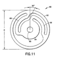
- the check valve 10 further includes a disk spring 60 formed from a substantially planar sheet of a hard metallic material that is substantially inert and that exhibits desirable spring characteristics.
- the disk spring 60 may be formed from an Elgiloy metallic alloy having a thickness of approximately 0,0178 cm (0.007 inch).
- Disk spring 60 is substantially circular and includes a substantially annular outer support rim 62, an annular inner support rim 64 and spring legs 66 extending therebetween, as shown in FIG. 11.
- the outer support rim 62 defines an outside diameter "e" which is greater than the inside diameter "a" of the chamber recesses 20 and 30, but slightly less than the inside diameter"b" of the retaining wall 28 on the first housing component 14.
- the annular outer support rim 62 of the spring 60 can be seated adjacent the stop face 26 of the first housing component 14 and can be retained in that position by the end face 34 of the second housing component 16.
- the annular inner support rim 64 of the disk spring 60 includes a central aperture 65 dimensioned to telescope over the backstop support 56 of the poppet 46.
- the annular inner support rim 64 further includes an outside diameter approximately equal to the outside diameter of the spring support face 54 of the poppet 46.
- each spring leg 66 extend substantially helically between the outer annular support 62 and the inner annular support 64. More particularly, each spring leg 66 includes a connecting portion that extends from the outer annular support 62 at an angle of approximately 30° to a radius of the spring 60 and an inner connecting portion that also is aligned at a slight angle to the radius. A generally circumferentially extending portion extends between these ends of each spring leg 66. This generally helical orientation of each spring leg 66 is provided to accommodate flexion or axial movement between the annular outer support rim 62 and the annular inner support rim 64 as the valve opens and closes.
- the spring legs 66 are not equally spaced around the center of the spring 60. More particularly, in the embodiment shown herein, two spring legs 60 are spaced from one another by approximately 120°. Thus, in this embodiment, a third spring leg that would have lead to an equal angular distribution of the spring legs 66 about the spring 60 is not provided. This non-symmetrical distribution of the spring leg 66 contributes to a desirable performance of the subject check valve, as explained below.
- the check valve 10 further includes a generally annular backstop 70 having a central aperture dimensioned to telescope over the backstop support 56 of the poppet 46.
- the backstop 70 further includes an outside diameter approximately equal to the outside diameter of the spring support 54.
- the check valve 10 is assembled by initially placing the central aperture of the annular inner support rim 64 of the spring 60 over the backstop support 56 until the annular inner support rim 64 of the spring 60 rests against the spring support face 54 of the poppet 44.
- the backstop 70 then is mounted over the backstop support 56 of the poppet 44. Portions of the backstop support 56 adjacent the concavity 58 then are welded to the backstop 70 or are deformed outwardly to securely retain the backstop support against the spring 60.
- the seal ring 52 then is urged into the annular undercut 48 in the sealing face 50 of the poppet 44.
- the subassembly comprising the poppet 46, the seal ring 48, the spring 60 and the backstop 70 then are positioned in the first chamber recess 20 of the first housing component 14, such that the sealing face 50 of the poppet 46 is positioned on the valve seat 22 of the first chamber recess 20.
- the annular outer support rim 62 of the spring 60 will be positioned on the stop face 26 of the first housing component 14.
- the cylindrical chamber wall 36 of the second housing component 16 then is telescoped into the engagement wall 28 of the first housing component 14. This telescoped engagement terminates when the end face 34 of the second housing component 16 securely engages against the annular outer support rim 62 of the spring 60.
- the telescoped first and second housing components 14 and 16 are secured to one another by a weldment 72 at the location indicated in FIG. 2. More particularly, the weldment 72 is disposed at the interface of the end 29 of the engagement wall 28 on the first housing component 14 and opposed portions of the second housing component 16. The weldment 72 will wick slightly into any minute annular space existing between the overlapped regions of the first and second housing components 14 and 16. However, due to the telescoped engagement of the first and second housing components 14 and 16, the weldment 72 will be spaced from the gas flow path, and the heat associated with the welding operation will be spaced from spring 60. Consequently the performance of the spring 60 will not be affected by the welding heat. In this construction, the valve chamber is securely sealed from ambient conditions and the spring is securely and mechanically held in position in a manner that will not affect the performance of the spring.
- the poppet 46 and the spring 60 bias the spring into a normally closed position.
- a gas flow through the inlet 18 of the check valve 10 will exert forces on the sealing face 50 of the poppet 46.
- Sufficient gas forces will overcome the biasing forces exerted by the spring 60 and will cause the sealing face 50 of the poppet 46 to move away from the valve seat 22 of the valve housing 12.
- the non-symmetrical configuration of the spring 60 will cause the side of the poppet 46 that is furthest from the spring legs 66 to lift initially from the valve seat 22. Remaining portions of the poppet 46 then will lift from the valve seat 22.
- the non-symmetrical configuration of the spring 60 will prevent creation of a resonant condition in which prior art valves would flutter and create noise.
- Movement of the poppet 46 will be terminated when the backstop 56 contacts all sections 42 of the valve housing 12 between adjacent channels 40 thereof. In this opened condition, gas will flow from the inlet 18 around the outer circumference of the poppet 46, through the channels 40 and into the outlet 38. Upon termination of the gas flow at the inlet 18, the biasing forces of the spring 60 will urge the sealing face 50 of the poppet 46 back into sealing engagement with the valve seat 22.
Landscapes
- Engineering & Computer Science (AREA)
- General Engineering & Computer Science (AREA)
- Mechanical Engineering (AREA)
- Check Valves (AREA)
Applications Claiming Priority (3)
| Application Number | Priority Date | Filing Date | Title |
|---|---|---|---|
| US9217998P | 1998-07-09 | 1998-07-09 | |
| US92179P | 1998-07-09 | ||
| PCT/US1999/013104 WO2000003167A1 (en) | 1998-07-09 | 1999-06-10 | Check valve |
Publications (2)
| Publication Number | Publication Date |
|---|---|
| EP1093555A1 EP1093555A1 (en) | 2001-04-25 |
| EP1093555B1 true EP1093555B1 (en) | 2003-04-09 |
Family
ID=22232023
Family Applications (1)
| Application Number | Title | Priority Date | Filing Date |
|---|---|---|---|
| EP99931784A Expired - Lifetime EP1093555B1 (en) | 1998-07-09 | 1999-06-10 | Check valve |
Country Status (5)
| Country | Link |
|---|---|
| US (1) | US6401749B1 (https=) |
| EP (1) | EP1093555B1 (https=) |
| JP (1) | JP4328022B2 (https=) |
| DE (1) | DE69906740T2 (https=) |
| WO (1) | WO2000003167A1 (https=) |
Families Citing this family (28)
| Publication number | Priority date | Publication date | Assignee | Title |
|---|---|---|---|---|
| EP1592083B1 (en) | 2000-01-19 | 2013-04-03 | Fractus, S.A. | Space-filling miniature antennas |
| GB0112784D0 (en) * | 2001-05-25 | 2001-07-18 | The Technology Partnership Plc | Pump |
| US6877525B2 (en) | 2001-11-07 | 2005-04-12 | Delphi Technologies, Inc. | Check valve for fuel pump |
| DE10224430A1 (de) * | 2002-06-01 | 2003-12-11 | Bosch Gmbh Robert | Rückschlagventil |
| US7125230B2 (en) * | 2002-07-09 | 2006-10-24 | Caterpillar Inc | Valve with operation parameter set at assembly and pump using same |
| US6971405B2 (en) * | 2002-10-09 | 2005-12-06 | Delphi Technologies, Inc. | Check valve for fuel pump |
| US6994108B2 (en) | 2003-03-04 | 2006-02-07 | Delphi Technologies, Inc. | Check valve for fuel pump |
| US7984728B2 (en) * | 2004-10-22 | 2011-07-26 | Continental Automotive Systems Us, Inc. | Fuel pressure regulator valve assembly |
| US20060108005A1 (en) * | 2004-11-24 | 2006-05-25 | Bennet Jan L | Pressure regulator valve biasing member with reticulated concentric rings |
| KR100598111B1 (ko) * | 2004-12-20 | 2006-07-07 | 삼성전자주식회사 | 레귤레이터 및 이를 사용하여 가스를 공급하는 방법 |
| DE102005046634A1 (de) * | 2005-09-28 | 2007-03-29 | Itt Richter Chemie-Technik Gmbh | Ventil mit federbelastetem Ventilstellglied |
| US8738103B2 (en) | 2006-07-18 | 2014-05-27 | Fractus, S.A. | Multiple-body-configuration multimedia and smartphone multifunction wireless devices |
| EP2044352A4 (en) * | 2006-07-25 | 2013-01-23 | Waters Technologies Corp | NON-RETURN VALVE WITH FLEXIBLE SEAL |
| DE102006036691B4 (de) * | 2006-08-05 | 2014-07-03 | Zf Friedrichshafen Ag | Rückschlagventil |
| US8302622B2 (en) * | 2010-02-24 | 2012-11-06 | Continental Automotive Systems Us, Inc. | Unbalanced inlet fuel tube for a fuel pressure regulator |
| DE102010030464A1 (de) * | 2010-06-24 | 2011-12-29 | Robert Bosch Gmbh | Rückschlagventil für eine Fluidpumpe |
| DE102011076361A1 (de) * | 2011-05-24 | 2012-11-29 | Bosch Mahle Turbo Systems Gmbh & Co. Kg | Ventileinrichtung |
| JP5947505B2 (ja) * | 2011-08-30 | 2016-07-06 | 株式会社堀場エステック | 流体制御弁 |
| JP5561492B2 (ja) | 2011-11-04 | 2014-07-30 | Smc株式会社 | チェック弁 |
| US10082088B2 (en) * | 2015-01-14 | 2018-09-25 | Hamilton Sundstrand Corporation | Flexure for metering valve assembly with retaining feature |
| US9745933B2 (en) | 2015-01-28 | 2017-08-29 | Delphi Technologies, Inc. | Fuel pressure regulator |
| SE541730C2 (en) | 2015-07-02 | 2019-12-03 | 3Eflow Ab | A fluid stop valve unit |
| US11052234B2 (en) * | 2017-02-15 | 2021-07-06 | Celeste V. Bonham | Connector with integrated non-return check valve for extension tubing and urology collection systems |
| US11035491B2 (en) * | 2017-07-03 | 2021-06-15 | Continental Automotive Systems, Inc. | Fuel pump solenoid having hydraulic damping |
| JP7320176B2 (ja) | 2018-04-23 | 2023-08-03 | デイコ アイピー ホールディングス,エルエルシー | 開位置を規定する逆止弁インサートおよび当該逆止弁インサートを有する逆止弁 |
| US11313482B2 (en) | 2019-11-14 | 2022-04-26 | Entegris, Inc. | Welded check valve |
| EP4214432A4 (en) | 2020-09-17 | 2024-05-29 | Fluid Handling LLC | CHECK VALVE ASSEMBLY WITH A CHECK VALVE ASSEMBLY CONNECTION FORMED BETWEEN A CHECK VALVE HOUSING, A CHECK VALVE BODY ADAPTER AND A LOCKING RING |
| CN113418033B (zh) * | 2021-07-21 | 2022-10-28 | 北京中科富海低温科技有限公司 | 一种低温止回阀及焊接工装 |
Family Cites Families (5)
| Publication number | Priority date | Publication date | Assignee | Title |
|---|---|---|---|---|
| GB644971A (en) * | 1948-09-17 | 1950-10-18 | Girling Ltd | A new or improved spring-loaded one-way valve for fluids |
| US2827077A (en) * | 1956-01-16 | 1958-03-18 | Mitchell Co John E | Flow control valve |
| BE791877A (fr) * | 1971-11-26 | 1973-03-16 | Bryan Donkin Co Ltd | Perfectionnement aux clapets de non-retour |
| US5727594A (en) | 1995-02-09 | 1998-03-17 | Choksi; Pradip | Low actuation pressure unidirectional flow valve |
| US5950652A (en) * | 1998-02-11 | 1999-09-14 | Parker Hannifin Corporation | Load balanced pressure regulator and method and apparatus for delivering process gas for manufacturing semiconductor devices employing same |
-
1999
- 1999-06-10 DE DE69906740T patent/DE69906740T2/de not_active Expired - Lifetime
- 1999-06-10 WO PCT/US1999/013104 patent/WO2000003167A1/en not_active Ceased
- 1999-06-10 JP JP2000559367A patent/JP4328022B2/ja not_active Expired - Lifetime
- 1999-06-10 EP EP99931784A patent/EP1093555B1/en not_active Expired - Lifetime
- 1999-06-10 US US09/623,099 patent/US6401749B1/en not_active Expired - Lifetime
Also Published As
| Publication number | Publication date |
|---|---|
| DE69906740D1 (de) | 2003-05-15 |
| JP4328022B2 (ja) | 2009-09-09 |
| DE69906740T2 (de) | 2004-01-29 |
| EP1093555A1 (en) | 2001-04-25 |
| JP2002520553A (ja) | 2002-07-09 |
| WO2000003167A1 (en) | 2000-01-20 |
| US6401749B1 (en) | 2002-06-11 |
Similar Documents
| Publication | Publication Date | Title |
|---|---|---|
| EP1093555B1 (en) | Check valve | |
| US10941867B2 (en) | High conductance valve for fluids and vapors | |
| EP0727603B1 (en) | Diaphragm valve | |
| EP1125074B1 (en) | Disc type check valve | |
| CA1160614A (en) | Sealing device for valves | |
| EP0357420B1 (en) | Non-return valve | |
| JPH0266378A (ja) | 締切兼流量調節弁 | |
| KR101736022B1 (ko) | 축방향으로 구속된 자가 정렬식 조절기 밸브 조립체 | |
| WO2021002140A1 (ja) | ボールバルブ | |
| JP2005069366A (ja) | バルブ | |
| US12104701B1 (en) | Resilient metal seal for check valve | |
| KR102216171B1 (ko) | 가변시트형 버터플라이밸브 | |
| JP7175497B2 (ja) | 逆止弁 | |
| CN114667423A (zh) | 动力元件以及使用了该动力元件的膨胀阀 | |
| US5161571A (en) | Check valve | |
| CN106917904A (zh) | 阀装置 | |
| JP2021124130A (ja) | 減圧弁、バルブユニット、弁装置、及び板ばね | |
| CN117980641A (zh) | 溢流阀和系统 | |
| JP7819339B2 (ja) | 減圧弁、及び弁装置 | |
| JP7651248B2 (ja) | 逆止弁 | |
| JPS62194079A (ja) | 液体流通導管用等のリテンシヨンバルブ | |
| JPH04210170A (ja) | ライン逆止弁 | |
| WO1992019894A1 (en) | Valves having a turnable valve member | |
| JPH1030743A (ja) | ばね付勢ディスク型逆止弁 | |
| CN118548339A (zh) | 一种控流结构及一种过流切断阀 |
Legal Events
| Date | Code | Title | Description |
|---|---|---|---|
| PUAI | Public reference made under article 153(3) epc to a published international application that has entered the european phase |
Free format text: ORIGINAL CODE: 0009012 |
|
| 17P | Request for examination filed |
Effective date: 20001109 |
|
| AK | Designated contracting states |
Kind code of ref document: A1 Designated state(s): DE FR GB |
|
| GRAH | Despatch of communication of intention to grant a patent |
Free format text: ORIGINAL CODE: EPIDOS IGRA |
|
| GRAH | Despatch of communication of intention to grant a patent |
Free format text: ORIGINAL CODE: EPIDOS IGRA |
|
| GRAA | (expected) grant |
Free format text: ORIGINAL CODE: 0009210 |
|
| AK | Designated contracting states |
Designated state(s): DE FR GB |
|
| REG | Reference to a national code |
Ref country code: GB Ref legal event code: FG4D |
|
| ET | Fr: translation filed | ||
| PLBE | No opposition filed within time limit |
Free format text: ORIGINAL CODE: 0009261 |
|
| STAA | Information on the status of an ep patent application or granted ep patent |
Free format text: STATUS: NO OPPOSITION FILED WITHIN TIME LIMIT |
|
| 26N | No opposition filed |
Effective date: 20040112 |
|
| REG | Reference to a national code |
Ref country code: FR Ref legal event code: PLFP Year of fee payment: 18 |
|
| REG | Reference to a national code |
Ref country code: FR Ref legal event code: PLFP Year of fee payment: 19 |
|
| REG | Reference to a national code |
Ref country code: FR Ref legal event code: PLFP Year of fee payment: 20 |
|
| PGFP | Annual fee paid to national office [announced via postgrant information from national office to epo] |
Ref country code: FR Payment date: 20180626 Year of fee payment: 20 |
|
| PGFP | Annual fee paid to national office [announced via postgrant information from national office to epo] |
Ref country code: GB Payment date: 20180627 Year of fee payment: 20 Ref country code: DE Payment date: 20180627 Year of fee payment: 20 |
|
| REG | Reference to a national code |
Ref country code: DE Ref legal event code: R071 Ref document number: 69906740 Country of ref document: DE |
|
| REG | Reference to a national code |
Ref country code: GB Ref legal event code: PE20 Expiry date: 20190609 |
|
| PG25 | Lapsed in a contracting state [announced via postgrant information from national office to epo] |
Ref country code: GB Free format text: LAPSE BECAUSE OF EXPIRATION OF PROTECTION Effective date: 20190609 |