EP1092879A1 - Vérin de suspension hydropneumatique de véhicule - Google Patents
Vérin de suspension hydropneumatique de véhicule Download PDFInfo
- Publication number
- EP1092879A1 EP1092879A1 EP00402794A EP00402794A EP1092879A1 EP 1092879 A1 EP1092879 A1 EP 1092879A1 EP 00402794 A EP00402794 A EP 00402794A EP 00402794 A EP00402794 A EP 00402794A EP 1092879 A1 EP1092879 A1 EP 1092879A1
- Authority
- EP
- European Patent Office
- Prior art keywords
- cylinder
- suspension
- cylinder according
- suspension cylinder
- tongue
- Prior art date
- Legal status (The legal status is an assumption and is not a legal conclusion. Google has not performed a legal analysis and makes no representation as to the accuracy of the status listed.)
- Granted
Links
- 239000000725 suspension Substances 0.000 title claims description 17
- 238000011084 recovery Methods 0.000 claims abstract description 7
- 230000002093 peripheral effect Effects 0.000 claims abstract description 3
- 230000001681 protective effect Effects 0.000 claims description 3
- 210000002105 tongue Anatomy 0.000 abstract description 10
- 230000008878 coupling Effects 0.000 abstract 1
- 238000010168 coupling process Methods 0.000 abstract 1
- 238000005859 coupling reaction Methods 0.000 abstract 1
- 239000012530 fluid Substances 0.000 description 6
- 238000007747 plating Methods 0.000 description 2
- 238000007789 sealing Methods 0.000 description 2
- 230000006835 compression Effects 0.000 description 1
- 238000007906 compression Methods 0.000 description 1
- 238000010586 diagram Methods 0.000 description 1
- 239000002184 metal Substances 0.000 description 1
- 230000010355 oscillation Effects 0.000 description 1
Images


Classifications
-
- B—PERFORMING OPERATIONS; TRANSPORTING
- B60—VEHICLES IN GENERAL
- B60G—VEHICLE SUSPENSION ARRANGEMENTS
- B60G21/00—Interconnection systems for two or more resiliently-suspended wheels, e.g. for stabilising a vehicle body with respect to acceleration, deceleration or centrifugal forces
- B60G21/02—Interconnection systems for two or more resiliently-suspended wheels, e.g. for stabilising a vehicle body with respect to acceleration, deceleration or centrifugal forces permanently interconnected
- B60G21/04—Interconnection systems for two or more resiliently-suspended wheels, e.g. for stabilising a vehicle body with respect to acceleration, deceleration or centrifugal forces permanently interconnected mechanically
- B60G21/05—Interconnection systems for two or more resiliently-suspended wheels, e.g. for stabilising a vehicle body with respect to acceleration, deceleration or centrifugal forces permanently interconnected mechanically between wheels on the same axle but on different sides of the vehicle, i.e. the left and right wheel suspensions being interconnected
- B60G21/055—Stabiliser bars
- B60G21/0551—Mounting means therefor
-
- F—MECHANICAL ENGINEERING; LIGHTING; HEATING; WEAPONS; BLASTING
- F15—FLUID-PRESSURE ACTUATORS; HYDRAULICS OR PNEUMATICS IN GENERAL
- F15B—SYSTEMS ACTING BY MEANS OF FLUIDS IN GENERAL; FLUID-PRESSURE ACTUATORS, e.g. SERVOMOTORS; DETAILS OF FLUID-PRESSURE SYSTEMS, NOT OTHERWISE PROVIDED FOR
- F15B15/00—Fluid-actuated devices for displacing a member from one position to another; Gearing associated therewith
- F15B15/08—Characterised by the construction of the motor unit
- F15B15/14—Characterised by the construction of the motor unit of the straight-cylinder type
- F15B15/149—Fluid interconnections, e.g. fluid connectors, passages
-
- F—MECHANICAL ENGINEERING; LIGHTING; HEATING; WEAPONS; BLASTING
- F16—ENGINEERING ELEMENTS AND UNITS; GENERAL MEASURES FOR PRODUCING AND MAINTAINING EFFECTIVE FUNCTIONING OF MACHINES OR INSTALLATIONS; THERMAL INSULATION IN GENERAL
- F16F—SPRINGS; SHOCK-ABSORBERS; MEANS FOR DAMPING VIBRATION
- F16F9/00—Springs, vibration-dampers, shock-absorbers, or similarly-constructed movement-dampers using a fluid or the equivalent as damping medium
- F16F9/32—Details
- F16F9/36—Special sealings, including sealings or guides for piston-rods
-
- F—MECHANICAL ENGINEERING; LIGHTING; HEATING; WEAPONS; BLASTING
- F16—ENGINEERING ELEMENTS AND UNITS; GENERAL MEASURES FOR PRODUCING AND MAINTAINING EFFECTIVE FUNCTIONING OF MACHINES OR INSTALLATIONS; THERMAL INSULATION IN GENERAL
- F16F—SPRINGS; SHOCK-ABSORBERS; MEANS FOR DAMPING VIBRATION
- F16F9/00—Springs, vibration-dampers, shock-absorbers, or similarly-constructed movement-dampers using a fluid or the equivalent as damping medium
- F16F9/32—Details
- F16F9/38—Covers for protection or appearance
-
- F—MECHANICAL ENGINEERING; LIGHTING; HEATING; WEAPONS; BLASTING
- F16—ENGINEERING ELEMENTS AND UNITS; GENERAL MEASURES FOR PRODUCING AND MAINTAINING EFFECTIVE FUNCTIONING OF MACHINES OR INSTALLATIONS; THERMAL INSULATION IN GENERAL
- F16F—SPRINGS; SHOCK-ABSORBERS; MEANS FOR DAMPING VIBRATION
- F16F9/00—Springs, vibration-dampers, shock-absorbers, or similarly-constructed movement-dampers using a fluid or the equivalent as damping medium
- F16F9/32—Details
- F16F9/43—Filling or drainage arrangements, e.g. for supply of gas
-
- B—PERFORMING OPERATIONS; TRANSPORTING
- B60—VEHICLES IN GENERAL
- B60G—VEHICLE SUSPENSION ARRANGEMENTS
- B60G2200/00—Indexing codes relating to suspension types
- B60G2200/10—Independent suspensions
- B60G2200/14—Independent suspensions with lateral arms
- B60G2200/142—Independent suspensions with lateral arms with a single lateral arm, e.g. MacPherson type
-
- B—PERFORMING OPERATIONS; TRANSPORTING
- B60—VEHICLES IN GENERAL
- B60G—VEHICLE SUSPENSION ARRANGEMENTS
- B60G2202/00—Indexing codes relating to the type of spring, damper or actuator
- B60G2202/10—Type of spring
- B60G2202/13—Torsion spring
- B60G2202/135—Stabiliser bar and/or tube
-
- B—PERFORMING OPERATIONS; TRANSPORTING
- B60—VEHICLES IN GENERAL
- B60G—VEHICLE SUSPENSION ARRANGEMENTS
- B60G2202/00—Indexing codes relating to the type of spring, damper or actuator
- B60G2202/10—Type of spring
- B60G2202/15—Fluid spring
- B60G2202/154—Fluid spring with an accumulator
-
- B—PERFORMING OPERATIONS; TRANSPORTING
- B60—VEHICLES IN GENERAL
- B60G—VEHICLE SUSPENSION ARRANGEMENTS
- B60G2204/00—Indexing codes related to suspensions per se or to auxiliary parts
- B60G2204/10—Mounting of suspension elements
- B60G2204/12—Mounting of springs or dampers
- B60G2204/122—Mounting of torsion springs
- B60G2204/1224—End mounts of stabiliser on wheel suspension
-
- B—PERFORMING OPERATIONS; TRANSPORTING
- B60—VEHICLES IN GENERAL
- B60G—VEHICLE SUSPENSION ARRANGEMENTS
- B60G2204/00—Indexing codes related to suspensions per se or to auxiliary parts
- B60G2204/40—Auxiliary suspension parts; Adjustment of suspensions
- B60G2204/422—Links for mounting suspension elements
Definitions
- the invention relates to a suspension cylinder motor vehicle hydropneumatic, of the type comprising a cylinder connected to a wheel by through a wheel support arm and in which is slidably mounted a piston articulated to the structure of the vehicle and with which the piston rod is provided an axial bore hydraulically connected to a hydropneumatic accumulator, recovery means internal leaks from the cylinder, means ensuring the sliding on the outer surface of the cylinder of a protective bellows of the jack and the support means of a cylinder end stop.
- the present invention aims to provide a cylinder hydropneumatic suspension, of the type described above, which overcomes the disadvantages of suspension cylinders known.
- the suspension cylinder according to the invention is characterized in that a single piece is scheduled to perform the three functions.
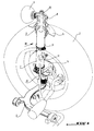
- Figure 1 is a perspective view of an arrangement of hydropneumatic vehicle suspension cylinder automobile, according to the present invention.
- Figure 2 is an exploded perspective view further large scale of the jack according to the invention.
- Figure 3 is an exploded perspective view of the part indicated in III in Figure 1.
- Figure 4 is an axial sectional view of the part illustrated in figure 3.
- Figure 5 is a top view showing the collar in its position before mounting the part on the cylinder.
- Figure 6 is a sectional view along line VI-VI of Figure 4 showing the collar in its position after mounting.
- a suspension cylinder motor vehicle hydropneumatics essentially comprises a cylinder 1, integral with a wheel 2 of the vehicle, via a pivot 3, articulated to a wheel support arm 4 and in which is sliding mounted a piston 5 articulated to the structure 6 of the vehicle.
- the piston rod 5 is provided with a bore axial hydraulically connected to an accumulator hydropneumatic 7 via a support accumulator 8.
- another anti-roll device including an anti-roll bar link 10 is fixed at 11 to the cylinder 1.
- Cylinder 1 is the outer body of a strut of the twin-tube type and coaxially encloses a body inner tubular 13 which receives an upper bearing 14 (fig. 2).
- the piston rod 5 is hollow and carries, at its end lower open, a guide head 15 provided with a segment 16. The head slides on the inside of the body tubular 13. The rod still carries, axially above of the head 15, a relaxation stop 17 bearing on a collar 18 secured to the rod.
- the end piston rod 5 is engaged in the central part 20 of the assembly formed by the accumulator 7 and its support 8.
- the piston also comprises, between its head 15 and its annular support flange 18, radial holes 20a which establish communication between the internal space of the hollow rod 5 and the chamber annular 21 delimited between the rod 5 and the body tubular 13 of the strut. Thanks to the orifices 20a, the chamber 23, delimited in the body 13 below of the piston head 15, is in communication, through the open lower end of the rod 5, with the room 21.
- the upper bearing 14 axially traversed by the rod piston 5 at the upper end of cylinder 1 is provided a dynamic sealing device 25 of the rod piston 5.
- a lip seal 26 is provided at the end upper of the bearing 14 between the bearing and the rod 5.
- the joint is arranged in an annular groove 27 formed in the upper face of the landing. The bottom of this groove communicates with the annular chamber 29 delimited between cylinder 1 and inner tubular body 13 via a conduit 30 internal to the bearing.
- the plating device 37 essentially comprises two axial tongues 39, 40, diametrically opposite, at the lower end of a cylindrical tubular body 41 made of plastic which covers the upper part of cylinder 1.
- each tongue is articulated respectively in 43 and 44 at the lower end of the tubular body 41.
- the tongue 39 constitutes the support for the connection of the leakage collector 32 on which is fitted the tubing 33 and it is crossed by a channel 46.
- the tab applies against the outside of the cylinder so that the channel 46 either in alignment with the passage opening of leak 31 in the wall of cylinder 1.
- the seal is provided by a seal 47 which is placed in a housing suitable 48 provided on the inside of the tongue 39.
- the tongue 40 is intended to come into application against the outside of cylinder 1, in the area diametrically opposite the tongue 39.
- a necklace of clamping 50 ensures the plating of the connection device of leakage return on cylinder 1.
- the collar can be a metal collar with snap closure, as shown in the figures, or screw.
- the collar 50 is arranged around the tabs 39, 40 by engaging in grooves collar retaining devices 51, provided on the tabs.
- the collar has at one end a eyelet 52 and at its other end an element latching 53 at two positions determined by two receiving eyelet 52, indicated at 54 and 55, which are arranged at a certain distance from each other in the direction of the periphery of cylinder 1. In the position 54 shown in FIG.
- the collar is located in a semi-latching position around the cylinder 1. In this position, the tabs are only not applied against cylinder 1 and are tilted the way shown in Figure 4.
- the eyelet 52 is engaged in the hollow 54 of the element latching 53.
- the tabs are pressed against the cylinder and the seal 47 is clamped between the cylinder 1 and the tongue 39 in its housing 48 in which it is permanently maintained by either adhesion, either by compression due to a form adapted to the shape of the housing.
- the collar In its semi-latching position, the collar allows the leak return collector to be sufficient away from the periphery of cylinder 1 to avoid any contact of the seal with the cylinder until obtaining the final position when the part 41 by fitting on the upper end of the cylinder.
- the definitive click of the collar guarantees the holding, in translation and in rotation, of the part 41 on the cylinder.
- the end closure wall 57 upper part of room 41, except for the passage of piston rod, provides the stop support function for end of stroke of the piston rod. This wall is reinforced to protect the lip seal 26.
- the actuator is provided with a bellows protection 59 (fig. 1) which is fixed at its end greater than a skirt 60 which surrounds the upper part of the jack and whose lower end 61 slides on the peripheral face of the part 41, in a sealed manner, along it.
- a bellows protection 59 (fig. 1) which is fixed at its end greater than a skirt 60 which surrounds the upper part of the jack and whose lower end 61 slides on the peripheral face of the part 41, in a sealed manner, along it.
Landscapes
- Engineering & Computer Science (AREA)
- General Engineering & Computer Science (AREA)
- Mechanical Engineering (AREA)
- Physics & Mathematics (AREA)
- Fluid Mechanics (AREA)
- Vehicle Body Suspensions (AREA)
- Fluid-Damping Devices (AREA)
Abstract
Description
Claims (9)
- Vérin de suspension hydropneumatique de véhicule automobile, du type comprenant un cylindre relié à une roue par l'intermédiaire d'un bras de support, et dans lequel est monté coulissant un piston articulé à la structure du véhicule et dont la tige de piston est munie d'un alésage axial relié hydrauliquement à un accumulateur hydropneumatique, des moyens de récupération des fuites internes du vérin, des moyens assurant le coulissement sur la surface extérieur du cylindre d'un soufflet protecteur du vérin et des moyens d'appui d'une butée de fin de course du vérin, caractérisé en ce qu'une seule pièce (41) est prévue pour accomplir les trois fonctions précitées de récupération des fuites, de coulissement et d'appui.
- Vérin de suspension selon la revendication 1, caractérisé en ce que la pièce (41) précitée présente une forme cylindrique et est emmanchée sur l'extrémité supérieure du cylindre (1) du vérin.
- Vérin de suspension selon la revendication 2, caractérisé en ce que les moyens qui accomplissent la fonction de récupération des fuites sont prévus sur l'extrémité inférieure ouverte de la pièce (41), sont susceptibles d'être serrés sur la périphérie du cylindre (1) et portent un raccord de retour de fuites (32).
- Vérin de suspension selon la revendication 3, caractérisé en ce que les moyens accomplissant la fonction de récupération des fuites comprennent deux éléments (39, 40) articulés au corps de la pièce (41), dont l'un (39) porte le raccord de retour de fuites.
- Vérin de suspension selon la revendication 4, caractérisé en ce que chaque élément (29, 30) est réalisé sous forme d'une languette s'étendant axialement à une extrémité de la pièce (41), en étant articulée à celle-ci, et en ce qu'un collier de serrage (50) est prévu pour plaquer les languettes sur le cylindre (1), ce dernier comportant un orifice de retour de fuites (31) communiquant avec le raccord de retour de fuites (32).
- Vérin de suspension selon la revendication 5, caractérisé en ce que la languette (39) porteuse du raccord de retour de fuites (32) est pourvue d'un joint (47) disposé sur la face interne de la languette de sorte que le joint (47) soit appliqué de façon étanche entre la surface périphérique du cylindre et la face interne de la languette (39) autour de l'orifice de sortie de fuites (31) lorsque cette languette est plaquée contre la surface du cylindre.
- Vérin de suspension selon l'une des revendications 1 à 6, caractérisé en ce que les moyens qui accomplissent la fonction d'appui de butée sont constitués par la partie supérieure (57) de la pièce cylindrique (41).
- Vérin de suspension selon la revendication 7, caractérisé en ce que la paroi (57) est renforcée.
- Vérin de suspension selon l'une des revendications précédentes, caractérisé en ce que les moyens accomplissant la fonction de maintien du soufflet de protection sont formés par la paroi latérale de la pièce cylindrique (41).
Applications Claiming Priority (2)
| Application Number | Priority Date | Filing Date | Title |
|---|---|---|---|
| FR9912703 | 1999-10-12 | ||
| FR9912703A FR2799514B1 (fr) | 1999-10-12 | 1999-10-12 | Verin de suspension hydropneumatique de vehicule |
Publications (2)
| Publication Number | Publication Date |
|---|---|
| EP1092879A1 true EP1092879A1 (fr) | 2001-04-18 |
| EP1092879B1 EP1092879B1 (fr) | 2004-07-07 |
Family
ID=9550827
Family Applications (1)
| Application Number | Title | Priority Date | Filing Date |
|---|---|---|---|
| EP00402794A Expired - Lifetime EP1092879B1 (fr) | 1999-10-12 | 2000-10-10 | Vérin de suspension hydropneumatique de véhicule |
Country Status (4)
| Country | Link |
|---|---|
| EP (1) | EP1092879B1 (fr) |
| AT (1) | ATE270754T1 (fr) |
| DE (1) | DE60011975T2 (fr) |
| FR (1) | FR2799514B1 (fr) |
Cited By (1)
| Publication number | Priority date | Publication date | Assignee | Title |
|---|---|---|---|---|
| WO2008019649A1 (fr) * | 2006-08-16 | 2008-02-21 | Zf Friedrichshafen Ag | Support oscillant |
Families Citing this family (1)
| Publication number | Priority date | Publication date | Assignee | Title |
|---|---|---|---|---|
| DE102009030591B4 (de) * | 2009-06-26 | 2015-05-13 | Zf Friedrichshafen Ag | Dämpferkappe eines Schwingungsdämpfers |
Citations (7)
| Publication number | Priority date | Publication date | Assignee | Title |
|---|---|---|---|---|
| GB2050559A (en) * | 1979-05-04 | 1981-01-07 | Iao Industrie Riunite Spa | Shock Absorbers for Use in Self- levelling Vehicle Suspensions |
| JPS60179315A (ja) * | 1984-02-28 | 1985-09-13 | Nhk Spring Co Ltd | 車両用懸架装置 |
| US4746106A (en) * | 1986-08-15 | 1988-05-24 | Nhk Spring Co., Ltd. | Car suspension system |
| FR2661731A1 (fr) * | 1990-05-07 | 1991-11-08 | Fichtel & Sachs Ag | Moyens de raccordement pour fluide. |
| US5402868A (en) * | 1991-11-28 | 1995-04-04 | Fichtel & Sachs Ag | Container piston device |
| JPH07280022A (ja) * | 1994-04-08 | 1995-10-27 | Toyota Motor Corp | リバウンドスプリング構造 |
| EP0724089A1 (fr) * | 1995-01-25 | 1996-07-31 | Automobiles Peugeot | Dispositif formant vérin hydraulique pouvant être utilisé dans une suspension hydropneumatique pour véhicule automobile |
-
1999
- 1999-10-12 FR FR9912703A patent/FR2799514B1/fr not_active Expired - Fee Related
-
2000
- 2000-10-10 DE DE60011975T patent/DE60011975T2/de not_active Expired - Lifetime
- 2000-10-10 EP EP00402794A patent/EP1092879B1/fr not_active Expired - Lifetime
- 2000-10-10 AT AT00402794T patent/ATE270754T1/de not_active IP Right Cessation
Patent Citations (7)
| Publication number | Priority date | Publication date | Assignee | Title |
|---|---|---|---|---|
| GB2050559A (en) * | 1979-05-04 | 1981-01-07 | Iao Industrie Riunite Spa | Shock Absorbers for Use in Self- levelling Vehicle Suspensions |
| JPS60179315A (ja) * | 1984-02-28 | 1985-09-13 | Nhk Spring Co Ltd | 車両用懸架装置 |
| US4746106A (en) * | 1986-08-15 | 1988-05-24 | Nhk Spring Co., Ltd. | Car suspension system |
| FR2661731A1 (fr) * | 1990-05-07 | 1991-11-08 | Fichtel & Sachs Ag | Moyens de raccordement pour fluide. |
| US5402868A (en) * | 1991-11-28 | 1995-04-04 | Fichtel & Sachs Ag | Container piston device |
| JPH07280022A (ja) * | 1994-04-08 | 1995-10-27 | Toyota Motor Corp | リバウンドスプリング構造 |
| EP0724089A1 (fr) * | 1995-01-25 | 1996-07-31 | Automobiles Peugeot | Dispositif formant vérin hydraulique pouvant être utilisé dans une suspension hydropneumatique pour véhicule automobile |
Non-Patent Citations (2)
| Title |
|---|
| PATENT ABSTRACTS OF JAPAN vol. 010, no. 021 (M - 449) 28 January 1986 (1986-01-28) * |
| PATENT ABSTRACTS OF JAPAN vol. 1996, no. 02 29 February 1996 (1996-02-29) * |
Cited By (1)
| Publication number | Priority date | Publication date | Assignee | Title |
|---|---|---|---|---|
| WO2008019649A1 (fr) * | 2006-08-16 | 2008-02-21 | Zf Friedrichshafen Ag | Support oscillant |
Also Published As
| Publication number | Publication date |
|---|---|
| FR2799514A1 (fr) | 2001-04-13 |
| DE60011975T2 (de) | 2005-08-18 |
| EP1092879B1 (fr) | 2004-07-07 |
| ATE270754T1 (de) | 2004-07-15 |
| DE60011975D1 (de) | 2004-08-12 |
| FR2799514B1 (fr) | 2002-01-11 |
Similar Documents
| Publication | Publication Date | Title |
|---|---|---|
| EP0360631A1 (fr) | Vérin de suspension hydropneumatique de véhicule | |
| FR2686659A1 (fr) | Emetteur hydraulique a reservoir integre et etanche. | |
| FR2806771A1 (fr) | Ressort pneumatique comportant un amortisseur d'oscillations variable en fonction de la pression de support | |
| FR2935032A1 (fr) | Cylindre de frein comportant une chambre de pression | |
| FR2661731A1 (fr) | Moyens de raccordement pour fluide. | |
| FR2522374A1 (fr) | Butee de debrayage hydraulique | |
| FR2551506A1 (fr) | ||
| FR2712374A1 (fr) | Procédé et dispositif destinés à remplir de gaz sous pression, une chambre de gaz d'un ensemble cylindre-piston. | |
| FR2716517A1 (fr) | Vanne rotative. | |
| EP0241353A1 (fr) | Perfectionnements aux supports antivibratoires de type hydraulique | |
| EP1092879B1 (fr) | Vérin de suspension hydropneumatique de véhicule | |
| FR2855239A1 (fr) | Raccord rapide pour conduites de fluide hydraulique | |
| EP1102694B1 (fr) | Dispositif simplifie de commande hydraulique d'un embrayage, notamment pour vehicule automobile | |
| FR2757234A1 (fr) | Maitre-cylindre pour embrayage a friction ou frein hydraulique de vehicule | |
| EP0244314B1 (fr) | Clapet d'écrétage à ouverture rapide pour élément de suspension hydropneumatique de véhicule lourd | |
| FR2716656A1 (fr) | Agencement de palier étanche pour le montage d'un arbre d'un mécanisme d'entraînement d'un essuie-glace. | |
| EP0724089B1 (fr) | Dispositif formant vérin hydraulique pouvant être utilisé dans une suspension hydropneumatique pour véhicule automobile | |
| FR2563304A1 (fr) | Verin amortisseur pour suspension oleopneumatique de vehicule | |
| FR2600394A1 (fr) | Soupape pour installations de chauffage de vehicules | |
| FR2510710A1 (fr) | Dispositif de fin de course pour directions hydrauliques assistees | |
| EP0029396A1 (fr) | Vanne à commande par un organe obturateur constringent | |
| FR2667666A1 (fr) | Amortisseur d'oscillations hydraulique a force d'amortissement variable. | |
| FR2853023A1 (fr) | Servo-verin | |
| FR2526904A1 (fr) | Dispositif de guidage et d'etancheite de la tige de piston d'un amortisseur mac pherson | |
| FR2556064A1 (fr) | Amortisseur hydraulique |
Legal Events
| Date | Code | Title | Description |
|---|---|---|---|
| PUAI | Public reference made under article 153(3) epc to a published international application that has entered the european phase |
Free format text: ORIGINAL CODE: 0009012 |
|
| AK | Designated contracting states |
Kind code of ref document: A1 Designated state(s): AT BE CH CY DE DK ES FI FR GB GR IE IT LI LU MC NL PT SE |
|
| AX | Request for extension of the european patent |
Free format text: AL;LT;LV;MK;RO;SI |
|
| 17P | Request for examination filed |
Effective date: 20011018 |
|
| AKX | Designation fees paid |
Free format text: AT BE CH CY DE DK ES FI FR GB GR IE IT LI LU MC NL PT SE |
|
| GRAP | Despatch of communication of intention to grant a patent |
Free format text: ORIGINAL CODE: EPIDOSNIGR1 |
|
| GRAS | Grant fee paid |
Free format text: ORIGINAL CODE: EPIDOSNIGR3 |
|
| GRAA | (expected) grant |
Free format text: ORIGINAL CODE: 0009210 |
|
| AK | Designated contracting states |
Kind code of ref document: B1 Designated state(s): AT BE CH CY DE DK ES FI FR GB GR IE IT LI LU MC NL PT SE |
|
| PG25 | Lapsed in a contracting state [announced via postgrant information from national office to epo] |
Ref country code: IE Free format text: LAPSE BECAUSE OF FAILURE TO SUBMIT A TRANSLATION OF THE DESCRIPTION OR TO PAY THE FEE WITHIN THE PRESCRIBED TIME-LIMIT Effective date: 20040707 Ref country code: AT Free format text: LAPSE BECAUSE OF FAILURE TO SUBMIT A TRANSLATION OF THE DESCRIPTION OR TO PAY THE FEE WITHIN THE PRESCRIBED TIME-LIMIT Effective date: 20040707 Ref country code: NL Free format text: LAPSE BECAUSE OF FAILURE TO SUBMIT A TRANSLATION OF THE DESCRIPTION OR TO PAY THE FEE WITHIN THE PRESCRIBED TIME-LIMIT Effective date: 20040707 Ref country code: FI Free format text: LAPSE BECAUSE OF FAILURE TO SUBMIT A TRANSLATION OF THE DESCRIPTION OR TO PAY THE FEE WITHIN THE PRESCRIBED TIME-LIMIT Effective date: 20040707 Ref country code: CY Free format text: LAPSE BECAUSE OF FAILURE TO SUBMIT A TRANSLATION OF THE DESCRIPTION OR TO PAY THE FEE WITHIN THE PRESCRIBED TIME-LIMIT Effective date: 20040707 |
|
| REG | Reference to a national code |
Ref country code: GB Ref legal event code: FG4D Free format text: NOT ENGLISH |
|
| REG | Reference to a national code |
Ref country code: CH Ref legal event code: EP |
|
| REG | Reference to a national code |
Ref country code: IE Ref legal event code: FG4D Free format text: FRENCH |
|
| REF | Corresponds to: |
Ref document number: 60011975 Country of ref document: DE Date of ref document: 20040812 Kind code of ref document: P |
|
| PG25 | Lapsed in a contracting state [announced via postgrant information from national office to epo] |
Ref country code: SE Free format text: LAPSE BECAUSE OF FAILURE TO SUBMIT A TRANSLATION OF THE DESCRIPTION OR TO PAY THE FEE WITHIN THE PRESCRIBED TIME-LIMIT Effective date: 20041007 Ref country code: GR Free format text: LAPSE BECAUSE OF FAILURE TO SUBMIT A TRANSLATION OF THE DESCRIPTION OR TO PAY THE FEE WITHIN THE PRESCRIBED TIME-LIMIT Effective date: 20041007 Ref country code: DK Free format text: LAPSE BECAUSE OF FAILURE TO SUBMIT A TRANSLATION OF THE DESCRIPTION OR TO PAY THE FEE WITHIN THE PRESCRIBED TIME-LIMIT Effective date: 20041007 |
|
| PG25 | Lapsed in a contracting state [announced via postgrant information from national office to epo] |
Ref country code: LU Free format text: LAPSE BECAUSE OF NON-PAYMENT OF DUE FEES Effective date: 20041010 |
|
| PG25 | Lapsed in a contracting state [announced via postgrant information from national office to epo] |
Ref country code: ES Free format text: LAPSE BECAUSE OF FAILURE TO SUBMIT A TRANSLATION OF THE DESCRIPTION OR TO PAY THE FEE WITHIN THE PRESCRIBED TIME-LIMIT Effective date: 20041018 |
|
| PG25 | Lapsed in a contracting state [announced via postgrant information from national office to epo] |
Ref country code: BE Free format text: LAPSE BECAUSE OF NON-PAYMENT OF DUE FEES Effective date: 20041031 Ref country code: LI Free format text: LAPSE BECAUSE OF NON-PAYMENT OF DUE FEES Effective date: 20041031 Ref country code: MC Free format text: LAPSE BECAUSE OF NON-PAYMENT OF DUE FEES Effective date: 20041031 Ref country code: CH Free format text: LAPSE BECAUSE OF NON-PAYMENT OF DUE FEES Effective date: 20041031 |
|
| GBT | Gb: translation of ep patent filed (gb section 77(6)(a)/1977) |
Effective date: 20041007 |
|
| NLV1 | Nl: lapsed or annulled due to failure to fulfill the requirements of art. 29p and 29m of the patents act | ||
| REG | Reference to a national code |
Ref country code: IE Ref legal event code: FD4D |
|
| BERE | Be: lapsed |
Owner name: PEUGEOT CITROEN AUTOMOBILES SA Effective date: 20041031 |
|
| PLBE | No opposition filed within time limit |
Free format text: ORIGINAL CODE: 0009261 |
|
| STAA | Information on the status of an ep patent application or granted ep patent |
Free format text: STATUS: NO OPPOSITION FILED WITHIN TIME LIMIT |
|
| REG | Reference to a national code |
Ref country code: CH Ref legal event code: PL |
|
| 26N | No opposition filed |
Effective date: 20050408 |
|
| REG | Reference to a national code |
Ref country code: GB Ref legal event code: 746 Effective date: 20070119 |
|
| BERE | Be: lapsed |
Owner name: S.A. *PEUGEOT CITROEN AUTOMOBILES Effective date: 20041031 |
|
| PG25 | Lapsed in a contracting state [announced via postgrant information from national office to epo] |
Ref country code: PT Free format text: LAPSE BECAUSE OF NON-PAYMENT OF DUE FEES Effective date: 20041207 |
|
| PGFP | Annual fee paid to national office [announced via postgrant information from national office to epo] |
Ref country code: IT Payment date: 20081016 Year of fee payment: 9 |
|
| PG25 | Lapsed in a contracting state [announced via postgrant information from national office to epo] |
Ref country code: IT Free format text: LAPSE BECAUSE OF NON-PAYMENT OF DUE FEES Effective date: 20091010 |
|
| PGFP | Annual fee paid to national office [announced via postgrant information from national office to epo] |
Ref country code: GB Payment date: 20110926 Year of fee payment: 12 |
|
| GBPC | Gb: european patent ceased through non-payment of renewal fee |
Effective date: 20121010 |
|
| PG25 | Lapsed in a contracting state [announced via postgrant information from national office to epo] |
Ref country code: GB Free format text: LAPSE BECAUSE OF NON-PAYMENT OF DUE FEES Effective date: 20121010 |
|
| REG | Reference to a national code |
Ref country code: FR Ref legal event code: PLFP Year of fee payment: 17 |
|
| PGFP | Annual fee paid to national office [announced via postgrant information from national office to epo] |
Ref country code: DE Payment date: 20160922 Year of fee payment: 17 |
|
| REG | Reference to a national code |
Ref country code: FR Ref legal event code: PLFP Year of fee payment: 18 |
|
| REG | Reference to a national code |
Ref country code: DE Ref legal event code: R119 Ref document number: 60011975 Country of ref document: DE |
|
| REG | Reference to a national code |
Ref country code: FR Ref legal event code: CA Effective date: 20180312 Ref country code: FR Ref legal event code: CD Owner name: PEUGEOT CITROEN AUTOMOBILES SA, FR Effective date: 20180312 |
|
| PG25 | Lapsed in a contracting state [announced via postgrant information from national office to epo] |
Ref country code: DE Free format text: LAPSE BECAUSE OF NON-PAYMENT OF DUE FEES Effective date: 20180501 |
|
| REG | Reference to a national code |
Ref country code: FR Ref legal event code: PLFP Year of fee payment: 19 |
|
| PGFP | Annual fee paid to national office [announced via postgrant information from national office to epo] |
Ref country code: FR Payment date: 20190919 Year of fee payment: 20 |