EP1091195A1 - Flow rate and flow velocity measurement device - Google Patents
Flow rate and flow velocity measurement device Download PDFInfo
- Publication number
- EP1091195A1 EP1091195A1 EP00308766A EP00308766A EP1091195A1 EP 1091195 A1 EP1091195 A1 EP 1091195A1 EP 00308766 A EP00308766 A EP 00308766A EP 00308766 A EP00308766 A EP 00308766A EP 1091195 A1 EP1091195 A1 EP 1091195A1
- Authority
- EP
- European Patent Office
- Prior art keywords
- flow
- divided
- passage
- flow pipe
- pipe
- Prior art date
- Legal status (The legal status is an assumption and is not a legal conclusion. Google has not performed a legal analysis and makes no representation as to the accuracy of the status listed.)
- Withdrawn
Links
Images


Classifications
-
- G—PHYSICS
- G01—MEASURING; TESTING
- G01F—MEASURING VOLUME, VOLUME FLOW, MASS FLOW OR LIQUID LEVEL; METERING BY VOLUME
- G01F1/00—Measuring the volume flow or mass flow of fluid or fluent solid material wherein the fluid passes through a meter in a continuous flow
- G01F1/05—Measuring the volume flow or mass flow of fluid or fluent solid material wherein the fluid passes through a meter in a continuous flow by using mechanical effects
- G01F1/34—Measuring the volume flow or mass flow of fluid or fluent solid material wherein the fluid passes through a meter in a continuous flow by using mechanical effects by measuring pressure or differential pressure
- G01F1/48—Measuring the volume flow or mass flow of fluid or fluent solid material wherein the fluid passes through a meter in a continuous flow by using mechanical effects by measuring pressure or differential pressure the pressure or differential pressure being created by a capillary element
-
- G—PHYSICS
- G01—MEASURING; TESTING
- G01F—MEASURING VOLUME, VOLUME FLOW, MASS FLOW OR LIQUID LEVEL; METERING BY VOLUME
- G01F1/00—Measuring the volume flow or mass flow of fluid or fluent solid material wherein the fluid passes through a meter in a continuous flow
- G01F1/68—Measuring the volume flow or mass flow of fluid or fluent solid material wherein the fluid passes through a meter in a continuous flow by using thermal effects
- G01F1/684—Structural arrangements; Mounting of elements, e.g. in relation to fluid flow
- G01F1/6842—Structural arrangements; Mounting of elements, e.g. in relation to fluid flow with means for influencing the fluid flow
Definitions
- the present invention relates to a device for measuring various quantities concerning a flow, among others, relates to a flow rate and flow velocity measurement device using a detection element integrally formed on a detection element and/or a semiconductor chip depending on temperature, and relates to a measurement device suitably applied, for example, as a combustion controlling mass flow rate sensor of an engine for a vehicle or industry, or a mass flow rate sensor for an industrial air conditioning system and compressor pressurized air supply system and, furthermore, an air/fuel ratio controlling flow rate sensor of a domestic gas hotplate.
- the housing structure of a sensor disclosed in the Japanese Patent Laid-Open No. 193863/1996 Gazette is effective for accumulation prevention of a pollution substance whose density is much higher than that of a measurement fluid but, as to the pollution substance whose density is relatively low, there is a fear that it enters into a divided flow passage and is accumulated onto the detection element. Further, in this sensor, since it is excessively intended to exclude an influence of the reverse flow, it becomes difficult to measure the reverse flow.
- a further high performance combustion controlling mass flow rate sensor for example, a sensor capable of detecting both of normal flow and reverse flow.
- a flow passage structure of the sensor capable of detecting the reverse flow has been proposed but, in the case where the reverse flow is measured, a detection output of the same level as the normal flow has not been obtained, so that it is considered that a detection output correction by a control circuit is necessary.
- An object of the invention is to provide a measurement device concerning a flow, in which an accumulation of the pollution substance onto the detection element is prevented.
- a further object of the invention is to provide a measurement device concerning a flow, which is capable of measuring the reverse flow similarly to the normal flow.
- a measurement device of a 1st aspect of the invention has: a divided flow pipe which has a divided flow pipe passage basically curved in ⁇ -shape form, and into which a flow in a main flow pipe, that is a detection object, is introduced; an inlet port of the divided flow pipe, which is formed in an outer peripheral side of the divided flow pipe, and opens in a face approximately orthogonal to a flow direction in the main flow pipe; a partition formed in the divided flow pipe; plural branch flow passages divided/formed by the partition so as to mutually branch and join in the divided flow pipe; and a detection element which is disposed so as to be exposed to a flow in, among the plural branch flow passages, the branch flow passage formed in the outer peripheral side of the divided flow pipe, and detects a quantity concerning the flow.
- a measurement fluid introduced into the divided flow pipe is sharply changed in its direction before it arrives an inlet of the branch flow passage in which the detection element exists. Therefore, the pollution substance whose inertia is high is prevented from entering into the branch flow passage in which the detection element exists.
- the divided flow pipe by means of further dividing the flow by the partition, it is possible to reduce a Reynolds number of the flow toward the detection element (because a flow sectional area becomes small), so that the flow in the vicinity of the detection element is adjusted and it is possible to perform a high accuracy detection.
- this measurement device by effectively branching the measurement fluid and changing it in its direction, in regard to both of the pollution substance mixed in the measurement fluid whose density is higher than that of the measurement fluid and the pollution substance whose density is relatively low, these pollution substances are all prevented from accumulating on a detection face of the detection element, so that there is provided a measurement device which is excellent in pollution resistance and whose detection output change is low over a long period.
- the divided flow pipe has a flow passage structure basically symmetrical with the detection element being made a center. According to the flow passage structure of such a symmetrical structure, since the flow in a divided flow pipe passage for the normal flow and the flow in the divided flow pipe passage for the reverse flow become symmetrical, it becomes unnecessary to particularly compensate a detection output in case of the reverse flow.
- the measurement device by constituting the measurement device on the basis of the 1st and 2nd aspects, as well as being excellent in pollution resistance, a similar detection output level can be obtained in regard to both of the normal flow and the reverse flow.
- a measurement device of a 3rd aspect of the invention has: a detection element which is disposed so as to be exposed to a flow in, among the plural branch flow passages, the branch flow passage formed in an inner peripheral side or an intermediate portion of the divided flow pipe, and detects a quantity concerning the flow; and a throttle formed in a flow passage between an inlet port of the divided flow pipe and an inlet of the branch flow passage in which a detection face of the detection element is exposed to the flow therein.
- a measurement device of a 4th aspect of the invention has: a divided flow pipe which has a divided flow pipe passage basically curved in ⁇ -shape form, and into which a flow in a main flow pipe, that is a detection object, is introduced; an inlet port of the divided flow pipe, which is formed in an one end outer peripheral side of the divided flow pipe passage, and opens in a face approximately orthogonal to a flow direction in the main flow pipe; an outlet port of the divided flow pipe, which is formed in the other end top of the divided flow pipe passage, and opens in a face approximately parallel to a flow direction in the main flow pipe; a partition which is formed in the divided flow pipe, one end of which extends till a vicinity of the inlet port, and the other end of which extends while being spaced from the outlet port; plural branch flow passages divided/formed by the partition so as to mutually branch and join in the divided flow pipe; and a detection element which is disposed so as to be exposed to a flow in, among the plural branch flow passages, the branch flow
- a measurement device of a 5th aspect of the invention has an inlet port of the divided flow pipe and an inlet of the branch flow passage, which are mutually formed such that the flow introduced into the divided flow pipe is changed in its direction and flows into the branch flow passage in which the detection element is exposed to the flow therein.
- a measurement device of a 6th aspect of the invention has a throttle formed in a flow passage between the inlet port of the divided flow pipe and an inlet of the branch flow passage such that the flow introduced into the divided flow pipe is changed in its direction and flows into the branch flow passage in which the detection element is exposed to the flow therein.
- a measurement device of a 7th aspect of the invention has a Venturi provided, on a wall face of the partition opposite to the detection element and from an upstream to a downstream of the detection element, such that a flow passage of the branch flow passage in which the detection element is disposed is made narrowest in the vicinity of a center of the detection element.
- an end portion of the partition does not extend to just below the inlet port of the divided flow pipe, and an inlet of the outer peripheral side branch flow passage in which the detection element is exposed to the flow therein does not open just below the inlet port of the divided flow pipe.
- a bypass flow passage short-circuiting between the inlet port and the outlet port of the divided flow pipe without passing through the plural branch flow passages.
- the orifice is provided in the bypass flow passage, and a flow rate of the measurement fluid toward the detection element is set by a protrusion amount of a flow passage wall forming the orifice or an orifice open area.
- a flow to be detected is constantly supplied to the detection face of the detection element, so that it is considered that it follows that the flow to be detected surely flows on the detection face.
- generations of vortex flow and exfoliation in the vicinity of the detection face are suppressed, it is considered that a detection accuracy and a reproducibility are improved.
- a flow passage face protruding than the detection face in at least an upstream, or an upstream and/or a downstream of the detection element.
- a form of the protrusion one capable of forming the flow obliquely impinging against the detection face suffices and, preferably, it is protruded concavely or convexly or its protruding surface is made a linear, polygonal or concave curved form slant face.
- the detection face of the detection element is exposed inside the divided flow pipe.
- a curved pipe (divided flow pipe) is attached in a direction orthogonal to the main flow pipe (measurement object pipe), and the detection element is provided in this curved portion (folded portion, a portion where the flow passage is curved) of the curved pipe.
- the detection element is disposed in a portion where the flow in the divided flow pipe is inverted or a portion where the flow direction is sharply changed or its vicinity. Also preferably, the detection face of the detection element is exposed to a portion where the flow in the divided flow pipe is speedy. Also preferably, the detection face of the detection element is exposed to a portion where the flow is throttled and subsequently changed in its direction in the divided flow pipe or its vicinity.
- this detection element is one in which basically four thin film resistors are provided in a semiconductor chip. More concretely, a diaphragm portion and a rim portion are provided on a semiconductor layer. In the diaphragm portion, there are provided (1) an upstream temperature sensor, (2) a downstream temperature sensor, and (3) a heater disposed between the upstream temperature sensor. On the other hand, in the rim portion, (4) an atmosphere temperature sensor is provided. The diaphragm portion is made very thin and a heat insulation is intended.
- it is one for, on the basis of temperature, measuring the quantity concerning a flow, at least including a flow rate and/or a flow velocity by the detection element.
- the measurement device according to the invention is installed in an intake system of engine of various vehicles, and can be applied to a measurement of intake quantity etc. of the engine mounted on a two-wheel or four-wheel vehicle.
- the measurement device according to the invention is installed between an air cleaner and a throttle valve in the intake system of engine mounted on the four-wheel vehicle.
- the measurement device according to the invention is attached, in the intake system of engine mounted on the two-wheel vehicle, to a two-wheel vehicle intake pipe (air funnel) connected to a cylinder in order to measure a flow rate or a flow velocity etc. of the intake.
- Fig. 1 is an explanatory view of a measurement device of an Embodiment 1 of the invention, and shows a longitudinal section along an axis direction of a main flow pipe.
- Fig. 2 is a partial enlarged view in which an inlet port 5 vicinity of a divided flow pipe 2 shown in Fig.1 is enlarged.
- Fig. 3 is a partial enlarged operation view in which the inlet port 5 vicinity of the divided flow pipe 2 shown in Fig.1 is enlarged.
- Fig. 4 is a partial enlarged view in which the divided flow pipe inlet port vicinity is enlarged in order to respectively explain a device of an Embodiment 2 of the invention.
- Fig. 5 is a partial enlarged view in which the divided flow pipe inlet port vicinity is enlarged in order to respectively explain a device of an Embodiment 3 of the invention.
- Fig. 6 is a partial enlarged view in which the divided flow pipe inlet port vicinity is enlarged in order to respectively explain a device of an Embodiment 4 of the invention.
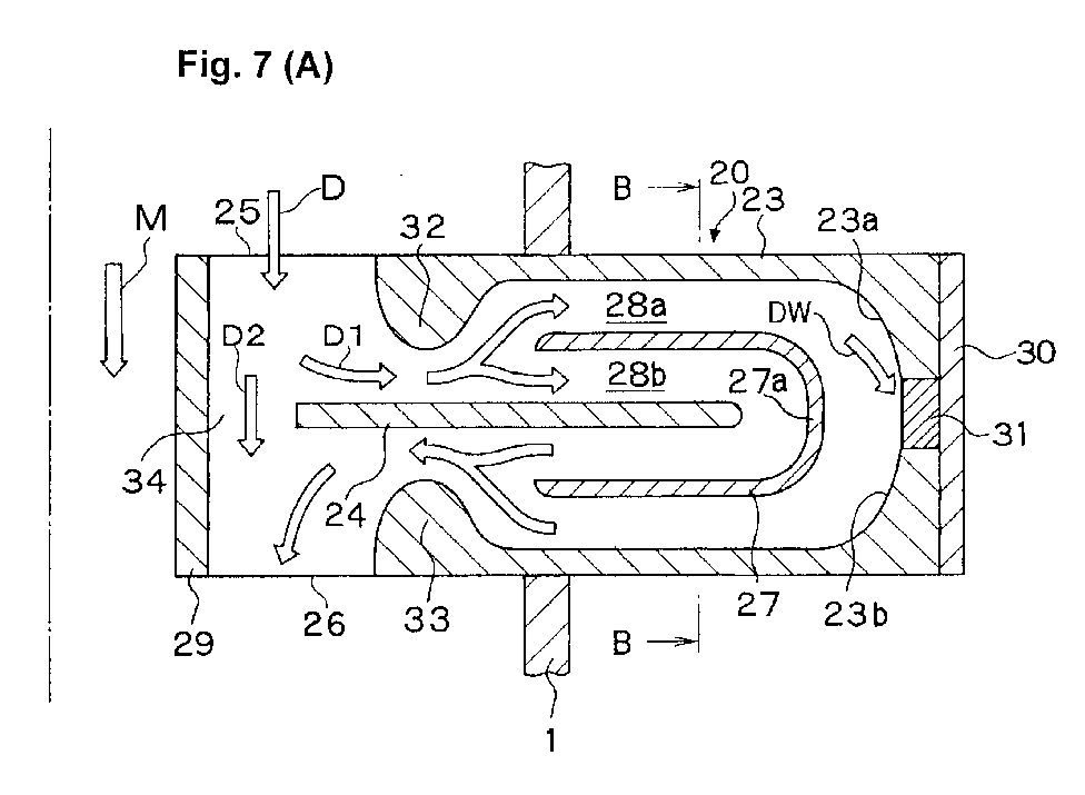
- FIG. 7 are explanatory views of a measurement device concerning a flow of an Embodiment 5 of the invention, wherein (A) shows a longitudinal section along the axis direction of the main flow pipe, and (B) a B-B section in (A).
- FIG. 8 are explanatory views of a device of an Embodiment 6 of the invention, wherein (A) is a partial enlarged sectional view (showing a section parallel to a flow section of a divided flow D) of a divided flow passage top outer wall and an inlet plate one end portion vicinity, and (B) a sectional view orthogonal to (A).
- Fig. 9 (A) to (C) are partial enlarged views showing a vicinity of an orifice bypassing the inlet port and an outlet port of the divided flow pipe in order to explain devices of Embodiments 7 to 9 of the invention in order, respectively.
- Fig. 10 is an explanatory view of a measurement device of a Comparison Example 1, and shows a longitudinal section along the axis direction of the main flow pipe.
- Fig. 11 is a graph showing flow rate characteristics of the device of the Comparison Example 1 shown in Fig. 10.
- Fig. 12 is a view in which the device of the Embodiment 5 explained by referring to Fig.7(A) and Fig.7(B) is depicted again.
- Fig. 13 is a graph showing flow rate characteristics of the device of the Embodiment 5 shown in Fig.12.
- Fig. 14 is an explanatory view of a measurement device of an Embodiment 10 of the invention, and shows a longitudinal section along the axis direction of the main flow pipe.
- Fig. 15 is an explanatory view of a measurement device of an Embodiment 11 of the invention, and shows a longitudinal section along the axis direction of the main flow pipe.
- Fig. 16 is an explanatory view of a measurement device of an Embodiment 12 of the invention, and shows a longitudinal section along the axis direction of the main flow pipe.
- Fig. 17 is an explanatory view of a measurement device of an Embodiment 13 of the invention, and shows a longitudinal section along the axis direction of the main flow pipe.
- Fig. 18 is an explanatory view of a measurement device of an Embodiment 14 of the invention, and shows a longitudinal section along the axis direction of the main flow pipe.
- Fig. 19 is an explanatory view of a measurement device of an Embodiment 15 of the invention, and shows a longitudinal section along the axis direction of the main flow pipe.
- Fig. 20 is an explanatory view of a measurement device of an Embodiment 16 of the invention, and shows a longitudinal section along the axis direction of the main flow pipe.
- Fig.21 is an explanatory view of a measurement device of an Embodiment 17 of the invention, and is a partial enlarged view of a detection element vicinity.
- Fig. 1 is an explanatory view of a measurement device according to an Embodiment 1 of the invention, and shows a longitudinal section along an axis direction of a main flow pipe.
- a main flow M which is a measurement object is flowing.
- a divided flow pipe 2 is mounted orthogonally to a pipe axis direction of the main flow pipe 1 so as to be able to take in a divided flow D separated from the main flow M.
- a divided flow pipe passage curved approximately in ⁇ -shape form is formed by an inlet plate 4 (main separator) extending in a direction approximately orthogonal to a flow direction (main flow pipe 1 pipe axis direction) of the main flow M.
- An inlet port (becoming also an outlet port) 5 opening in a face approximately orthogonal to the flow direction of the main flow M is formed in one end of an outer wall of the divided flow pipe 2, and an outlet port (becoming also an inlet port) 6 opening in a face approximately parallel to the flow direction of the main flow M is formed in a top outer wall, of the divided flow pipe 2, extending along the main flow pipe 1 pipe axis direction.
- a partition 7 curved complying with a curved shape of the divided flow pipe 2 is formed.
- plural branch flow passages 8a, 8b mutually branching and joining.
- a detection element 11 is attached through a base plate 10 so as to be exposed to a flow in the outer peripheral side branch flow passage 8a. In this manner, the detection element 11 is disposed in a curved portion of the divided flow pipe 2 and, further, positioned outside the main flow pipe 1 so as to be easy to exchange.
- Fig.2 is a partial enlarged view in which a vicinity of the inlet port 5 of the divided flow pipe 2 shown in Fig.1 is enlarged.
- an inlet port 5 side end portion of the partition 7 exists in a position retracted by a distance L than a partition 7 side opening inner wall of the inlet port 5. That is, the end portion of the partition 7 does not extend to just below the inlet port 5, and at least an inlet of the outer peripheral side branch flow passage 8a does not open just below the inlet port 5.
- protuberances 3a, 3b protruding toward a flow section center of the branch flow passage 8a are formed so as to put the detection element 11 between them on its both sides.
- a protrusion portion 7a protruding toward the detection face is formed in a portion of the partition 7 opposite to a detection face of the detection element 11.
- a flow passage face on the protuberances 3a, 3b is formed in a concave curved face.
- a flow passage face of the protrusion portion 7a is formed in a convex curved face which is convex toward the detection element 11.
- Fig.3 is a partial enlarged operation view in which a vicinity of the inlet port 5 of the divided flow pipe 2 shown in Fig.1 is enlarged.
- the divided flow D separated from the main flow M is taken into the divided flow pipe 2 from the inlet port 5.
- the divided flow D is changed in its direction and flows into the outer peripheral side and inner peripheral side branch flow passages 8a, 8b.
- a pollution substance P whose density is higher than that of the measurement flow cannot follow completely to the change in the flow direction, so that it advances straight by an inertia to stagnate just below the inlet port 5 or enters into the inner peripheral side branch flow passage 8b.
- Fig.4 to Fig.6 are partial enlarged views in which a vicinity of the inlet port of the divided flow pipe is enlarged for respectively explaining in order the measurement devices of the Embodiments 2 to 4 of the invention.
- the structures other than the portions shown in Fig.4 to Fig.6 are basically similar to the device of the Embodiment 1.
- an undulation portion 12 in the measurement device of the Embodiment 2, inside the outer wall 3 of the divided flow pipe, in the vicinity of the inlet port 5 there is formed an undulation portion 12 so as to clog an inlet of the outer peripheral side branch flow passage 8a.
- An apex of the undulation portion 12 protrudes by a height H1 toward the inlet plate 4 beyond an inner peripheral side flow passage face of the outer peripheral side branch flow passage 8a formed on the partition 7.
- a throttle is formed in a flow passage between the inlet port 5 of the divided flow pipe 2 and the inlet of the outer peripheral side branch flow passage 8a in which the detection element 11 is dispposed.
- an undulation portion 13 having a flow passage face of a concave curved face form is formed in an inner peripheral side flow passage wall (between the inlet plate and a top outer wall of the divided flow pipe) forming the divided flow pipe passage.
- the flow toward the branch flow passages 8a, 8b is adjusted.
- an undulation portion 14 in the measurement device of the Embodiment 4, in an inlet port 5 side inner wall of the inlet plate 4 there is formed an undulation portion 14 so as to clog an inlet of the inner peripheral side branch flow passage 8b.
- An apex of the undulation portion 14 protrudes by a height H2 toward the outer wall 3 beyond an outer peripheral side flow passage face of the inner peripheral side branch flow passage 8b formed on the partition 7.
- a throttle is formed in a flow passage between the inlet port 5 of the divided flow pipe 2 and the inlet of the inner peripheral side branch flow passage 8b and, further, a stagnant portion is formed in a left side of the undulation portion 14 in Fig.6.
- Fig.7(A) and Fig.7(B) are explanatory views of the measurement device concerning a flow of the Embodiment 5 of the invention, wherein Fig.7(A) is a longitudinal section along the axis direction of the main flow pipe, and Fig.7(B) shows a B-B section in Fig.7(A).
- the main flow M which is a measurement object, is flowing.
- a divided flow pipe 20 is mounted orthogonally to the pipe axis direction of the main flow pipe 1 so as to be able to take in the divided flow D separated from the main flow M.
- the divided flow pipe passage curved approximately in ⁇ -shape is formed by an inlet plate 24 (main separator) extending in a direction approximately orthogonal to the flow direction (main flow pipe 1 pipe axis direction) of the main flow M.
- An inlet port (becoming also an outlet port) 25 and an outlet port (becoming also an inlet port) 26 respectively opening in faces approximately orthogonal to the flow direction of the main flow M are oppositely formed in both ends of an outer wall 23 of the divided flow pipe 20.
- a bypass flow passage 34 is formed between a top outer wall 29 of the divided flow pipe 20 and one end of the inlet plate 24, thereby short-circuiting between an inlet port 25 and an outlet port 26.
- the divided flow D is sharply changed in its direction approximately at a right angle, so that a 1st divided flow D1 whose pollution substance content is low flows toward inlets of plural branch flow passages 28a, 28b mentioned later, while the pollution substance whose density is relatively high is carried by a 2nd divided flow D2 and advances straight from the inlet port 25 to the outlet port 26 via the bypass flow passage 34 and is discharged outside the divided flow pipe 20 (a reverse of this is similar as well).
- a partition 27 curved complying with a curved shape of the divided flow pipe 20.
- the plural branch flow passages 28a, 28b mutually branching and joining.
- undulation portions 32, 33 are respectively formed so as to clog an inlet and an outlet of the outer peripheral side branch flow passage 28a.
- throttles are formed respectively in a passage between the inlet port 25 and the inlet of the outer peripheral side branch flow passage 28a and a flow passage between the outlet port 26 and the outlet of the outer peripheral side branch flow passage 28a.
- a detection element 31 is attached through a base plate 30 so as to be exposed to a flow in the outer peripheral side branch flow passage 28a.
- the detection element 31 is disposed in a curved portion of the divided flow pipe 20 and, further, positioned outside the main flow pipe 1 so as to be easy to exchange.
- protuberances 23a, 23b protruding toward a flow section center of the branch flow passage 28a are formed so as to put the detection element 31 between them on its both sides.
- a protrusion portion 27a protruding toward the detection face is formed in a portion of the partition 27 opposite to a detection face of the detection element 31, a protrusion portion 27a protruding toward the detection face is formed.
- a flow passage face on the protuberances 23a, 23b is formed in a concave curved face.
- a flow passage face of the protrusion portion 27a is formed in a convex curved face which is convex toward the detection element 31.
- this divided flow pipe 20 there is formed a flow passage structure along the flow direction in the divided flow pipe passage of approximately ⁇ -shape form and symmetrical with the detection element 31 being made a center. Therefore, according to this divided flow pipe 20, the accumulation of the pollution substance onto the detection element 31 is prevented and, besides, it is possible to measure both of the normal flow and the reverse flow with an equivalent detection output level.
- Fig.8(A) and Fig.8(B) are explanatory views of the device of the Embodiment 6 of the invention, wherein Fig.8(A) is a partial enlarged sectional view (showing a section parallel to a flow section of the divided flow D) in the vicinity of the divided flow pipe top outer wall and the inlet plate one end portion, and Fig.8(B) a sectional view orthogonal to Fig.8(A).
- the structure other than the portions shown in Fig.8(A) and Fig.8(B) is basically similar to the device of the Embodiment 5.
- an orifice member 35 is attached or integrally formed between the top outer wall 29 of the divided flow pipe and one end of the inlet plate 24, i.e., in the bypass flow passage (34 in Fig.7(A)) in the Embodiment 5.
- Fig.9(A) to Fig.9(C) are partial enlarged views showing a vicinity of an orifice bypassing between an inlet port and an outlet port of the divided flow pipe in order to respectively explain in order the devices of the Embodiments 7 to 9 of the invention.
- the structures other than the portions shown in the drawings are basically similar to the device of the Embodiment 6.
- triangle protrusion portions 40a, 4la are respectively formed in one end of an inlet plate 41 and a top outer wall 40 opposite to the one end and, by these protrusion portions 40a, 41a, an orifice is formed in the bypass flow passage short-circuiting between the inlet port and the outlet port of the divided flow pipe.
- one end 43a of an inlet plate 43 is rectangular and a polygonal protrusion portion 42a is formed in a top outer wall 42 opposite to the one end 43a and, by the one end 43a and the polygonal protrusion portion 42a, an orifice is formed in the bypass flow passage short-circuiting between the inlet port and the outlet port of the divided flow pipe.
- one end 45a of an inlet plate 45 is rectangular and a curved face form (semicircular) protrusion portion 44a is formed in a top outer wall 44 opposite to the one end 45a and, by the one end 45a and the curved face form protrusion portion 44a, an orifice is formed in the bypass flow passage short-circuiting between the inlet port and the outlet port of the divided flow pipe.
- a sensor (detection) output of a measurement device of a Comparison Example 1 and a sensor output of the measurement device of the Embodiment 5 are explained in comparison.
- a structure of the measurement device of the Comparison Example 1 is explained mainly concerning points of difference from the measurement device of the Embodiment 5.
- Fig.10 is an explanatory view of the measurement device of the Comparison Example 1, and shows a longitudinal section along the axis direction of the main flow pipe. Referring to Fig.10, in the pipe wall of the main flow pipe 1, a divided flow pipe 52 is mounted orthogonally to the pipe axis direction of the main flow pipe 1 so as to be able to take in the divided flow D separated from the main flow M.
- a divided flow pipe passage curved approximately in ⁇ -shape form is formed by an inner wall 54 (main separator).
- an inlet port (becoming also an outlet port) 55 of the curved divided flow pipe passage is formed in a face approximately orthogonal to the flow direction of the main flow M
- an outlet port (becoming also an inlet port) 56 of the divided flow pipe passage opening in a face approximately parallel to the flow direction of the main flow M is formed in a top outer wall, of the divided flow pipe 52, extending along the main flow pipe 1 pipe axis direction.
- the divided flow pipe passage is reduced in its diameter (a reduced diameter portion 63 is formed) toward a detection element 61 side along a flow direction from the inlet port 55 toward the outlet port 56, and it is increased in its diameter (an increased diameter portion 64 is formed) between the detection element 61 and the outlet port 56.
- protuberances 53a, 53b protruding toward a flow section center of the divided flow pipe passage are formed so as to put the detection element 61 between them on its both sides.
- a flow passage face on the protuberances 53a, 53b is formed in a concave curved face.
- a protrusion portion 54a protruding toward the detection face is formed in a portion of the inner wall 54 of the divided flow pipe 52 opposite to the detection element 61 .
- a flow passage face of the protrusion portion 54a is formed in a convex curved face which is convex toward the detection element 61.
- Fig.l 1 is a graph showing flow rate characteristics of the device of the Comparison Example 1 shown in Fig.10.
- Fig.10 according to the measurement device of the Comparison Example 1, since along the flow direction there is formed a flow passage structure asymmetrical with the detection element 61 being made a center, it is impossible to detect with an equivalent detection output level both of the normal flow (flow from the inlet port 55 toward the outlet port 56) and the reverse flow (flow from the outlet port 56 toward the inlet port 55).
- Fig.12 is a view in which the device of the Embodiment 5 explained by referring to Fig.7(A) and Fig.7(B) mentioned before is depicted again, and Fig.13 a graph showing flow rate characteristics of the device of the Embodiment 5.
- Fig.12 within the divided flow pipe 20 in the measurement device of the Embodiment 5, along the flow direction there is formed a flow passage structure symmetrical with the detection element 31 being made a center.
- Fig.13 therefore, by using this divided flow pipe 20, it is possible to detect with an equivalent detection output level both of the normal flow (flow from the inlet port 25 toward the outlet port 26) and the reverse flow (flow from the outlet port 26 toward the inlet port 25).
- Embodiments 10 to 15 of the measurement device according to the invention are explained. Incidentally, in the explanations recited below about the Embodiments 10 to 15, in order to avoid repetitions of the description, points of difference from the measurement device concerning a flow of the Embodiment 5 are mainly explained, and it is construed that the descriptions relating to the Embodiment 5 are referred as to the similar points. Further, the flow passage structure in the divided flow pipe in each of the Embodiments 10 to 14 is symmetrical along the flow direction with the detection element being made a center, and can measure with an equivalent detection output level both of the normal flow and the reverse flow. Further, the measurement device of the Embodiment 15 is suitable for measuring the normal flow.
- Fig.14 is an explanatory view of the measurement device of an Embodiment 10 of the invention, and shows a longitudinal section along the axis direction of the main flow pipe.
- a divided flow pipe passage curved approximately in ⁇ -shape form is formed by an inlet plate 94 extending in a direction approximately orthogonal to the flow direction of the main flow M.
- an inlet port 95 and an outlet port 96 opening in faces approximately orthogonal to the flow direction of the main flow M are oppositely formed.
- a curved partition 97 there are formed plural branch flow passages 98a, 98b mutually branching and joining.
- a detection element 101 is attached through a base plate 100.
- protuberances 93a, 93b are formed so as to put the detection element 101 between them on its both sides.
- a protrusion portion 97a protruding toward a detection face of the detection element 101 is formed.
- a triangle protrusion portion 99a is formed inside a top outer wall 99 opposite to one end of the inlet plate 94, and an orifice 104 is formed in a bypass flow passage short-circuiting between the inlet port 95 and the outlet port 96.
- Fig.15 is an explanatory view of the measurement device of an Embodiment 11 of the invention, and shows a longitudinal section along the axis direction of the main flow pipe.
- a divided flow pipe passage curved approximately in ⁇ -shape form is formed by an inlet plate 114 extending in a direction approximately orthogonal to the flow direction of the main flow M.
- an inlet port 115 and an outlet port 116 opening in faces approximately orthogonal to the flow direction of the main flow M are oppositely formed.
- curved partitions 137, 138 there are formed, from an outer peripheral side toward an inner peripheral side in order, plural branch flow passages 118a, 118c, 118b mutually branching and joining.
- undulation portions 122, 123 are respectively formed so as to respectively clog inlets and outlets of the branch flow passages 118a, 118c.
- throttles are formed respectively in a flow passage between the inlet port 115 and the inlets of the branch flow passages 118a, 118c and a flow passage between the outlet port 116 and the outlets of the branch flow passages 118a, 118c.
- a detection element 121 is attached through a base plate 120.
- protuberances 113a, 113b are formed so as to put the detection element 121 between them on its both sides.
- a protrusion portion 137a protruding toward a detection face of the detection element 121 is formed in the partition 137.
- Fig.16 is an explanatory view of the measurement device of an Embodiment 12 of the invention, and shows a longitudinal section along the axis direction of the main flow pipe.
- a divided flow pipe passage curved approximately in ⁇ -shape form is formed by a inlet plate 144 extending in a direction approximately orthogonal to the flow direction of the main flow M.
- inlet port 145 opening in a face approximately parallel to the flow direction of the main flow M
- an outlet port 146 opening in a face approximately orthogonal to the same.
- the divided flow D is introduced into the divided flow pipe 142 mainly from a slant direction. Further, within the divided flow pipe 142, by a curved partition 147 there are formed plural branch flow passages 148a, 148b mutually branching and joining. Inside both end portions of the outer wall 143 (in the vicinity of the inlet port 145 and the outlet port 146), undulation portions 152, 153 are respectively formed so as to respectively clog an inlet and an outlet of the outer peripheral side branch flow passages 148a.
- throttles are formed respectively in a flow passage between the inlet port 145 and the inlet of the outer peripheral side branch flow passages 148a, and a flow passage between the outlet port 146 and the outlet of the outer peripheral side branch flow passages 148a.
- a detection element 151 is attached through a base plate 150.
- protuberances 143a, 143b are formed so as to put the detection element 151 between them on its both sides.
- a protrusion portion 147a protruding toward a detection face of the detection element 151 is formed.
- Fig.17 is an explanatory view of the measurement device of an Embodiment 13 of the invention, and shows a longitudinal section along the axis direction of the main flow pipe.
- a divided flow pipe passage curved approximately in ⁇ -shape form is formed by a inlet plate 164 extending in a direction approximately orthogonal to the main flow pipe 1 pipe axis direction.
- an inlet port 165 and an outlet port 166 opening in a face approximately orthogonal to the main flow M In both ends of an outer wall 163 of the divided flow pipe 162, there are oppositely formed an inlet port 165 and an outlet port 166 opening in a face approximately orthogonal to the main flow M.
- a curved partition 167 there are formed plural branch flow passages 168a, 168b mutually branching and joining.
- undulation portions 172, 173 are respectively formed so as to respectively clog an inlet and an outlet of the outer peripheral side branch flow passages 168a.
- throttles are formed respectively in a flow passage between the inlet port 165 and the inlet of the outer peripheral side branch flow passages 168a, and a flow passage between the outlet port 166 and the outlet of the outer peripheral side branch flow passages 168a.
- Both sides of one end of the inlet plate 164 are respectively enlarged toward the inlet port 165 and the outlet port 166, and a bypass flow passage 174 shirt-circuiting between the inlet port 165 and the outlet port 166 is formed between this enlarged portion and a top outer wall 169 opposite to a bottom face of the enlarged portion.
- a detection element 171 is attached through a base plate 170.
- protuberances 163a, 163b are formed so as to put the detection element 171 between them on its both sides.
- a protrusion portion 167a protruding toward a detection face of the detection element 171 is formed in an intermediate portion of the partition 167.
- Fig.18 is an explanatory view of the measurement device of an Embodiment 14 of the invention, and shows a longitudinal section along the axis direction of the main flow pipe.
- a divided flow pipe passage curved approximately in ⁇ -shape form is formed by a inlet plate 184 extending in a direction approximately orthogonal to the main flow pipe 1 pipe axis direction.
- an inlet port 185 and an outlet port 186 opening in a face approximately orthogonal to the flow direction of the main flow M.
- a curved partition 187 there are formed plural branch flow passages 188a, 188b mutually branching and joining.
- undulation portions 192, 193 are respectively formed so as to respectively clog an inlet and an outlet of the outer peripheral side branch flow passages 188a.
- undulation portions 202, 203 are respectively protruding toward an inside of the outer wall 183.
- throttles are formed stepwise in a flow passage between the inlet port 185 and the inlet of the inner peripheral side branch flow passage 188b and a flow passage between the outlet port 186 and the outlet of the inner peripheral side branch flow passage 188b, respectively.
- a bypass flow passage 194 short-circuiting between the inlet port 185 and the outlet port 186 is formed between one end of the inlet plate 184 and a top outer wall 189 opposite to the one end.
- a detection element 191 is attached such that its detection face is exposed to the flow in the inner peripheral side branch flow passage 188b.
- a curved face protrusion portion 184a protruding toward a detection face of the detection element 191 is formed in the other end of the inlet plate 184.
- Fig.19 is an explanatory view of the measurement device of an Embodiment 15 of the invention, and shows a longitudinal section along the axis direction of the main flow pipe.
- a divided flow pipe passage curved approximately in ⁇ -shape form is formed by a inlet plate 224 extending in a direction approximately orthogonal to the flow direction of the main flow M.
- an inlet port 225 opening in a face approximately orthogonal to the flow direction of the main flow M
- outlet port 226 opening in a face approximately parallel to the flow direction of the main flow M.
- a curved partition 227 there are formed plural branch flow passages 228a, 228b mutually branching and joining.
- the other end of the outlet port 226 side of the partition 227 is largely spaced from the outlet port 226 in comparison with one end of the inlet port 225 side of the same.
- an undulation portion 232 is formed so as to clog an inlet of the outer peripheral side branch flow passage 228a.
- an undulation portion 242 is formed.
- a throttle is formed in a flow passage between the inlet port 225 and an inlet of the branch flow passage 228a.
- a detection element 231 is attached through a base plate 230.
- protuberances 223a, 223b are formed so as to put the detection element 231 between them on its both sides.
- a protrusion portion 227a protruding toward a detection face of the detection element 231 is formed.
- Fig.20 is an explanatory view of the measurement device of an Embodiment 16 of the invention.
- this Embodiment 16 is a modification example of the Embodiment 5, so that in this Embodiment 16 the same reference signs as the Embodiment 5 are given to elements similar to the Embodiment 5.
- the explanations of the Embodiment 5 can be suitably referred.
- a Venturi (Venturi wall portion) 250 is provided from the upstream to the down stream of the detection element 31.
- a flow passage of the outer peripheral side branch flow passage 28a in which the detection element 31 is disposed is made narrowest in the vicinity of a center of the detection element 31 (this is referred to as "narrowest portion N").
- Fig.21 is an explanatory view of the measurement device of an Embodiment 17 of the invention, and is an enlarged view in the vicinity of the detection element.
- this Embodiment 17 is a modification example of the Embodiment 16, so that portions in which there are differences between the measurement devices of this Embodiment 17 and the Embodiment 16 are explained in the following explanations and, as to portions in which both have similar constitutions and functions, it is construed that the explanations of the Embodiment 16 can be suitably referred.
- a partition 270 within the divided flow pipe there are formed an outer peripheral side branch flow passage 278a and an inner peripheral side branch flow passage 278b.
- a detection element 281 is attached through a base plate 280 and exposed to the flow in the outer peripheral side branch flow passage 278a.
- a Venturi 290 is provided from the upstream to the down stream of the detection element 281.
- a flow passage of the outer peripheral side branch flow passage 278a in which the detection element 281 is disposed is made narrowest in the vicinity of a center of the detection element 281 (this is referred to as "narrowest portion N").
- a measurement device concerning a flow in which an accumulation of pollution substance on to a detection element is prevented. Further, according to the invention, there is provided a measurement device concerning a flow, which can measure a reverse flow similarly to a normal flow.
- the divided flow pipe passage is described herein as being curved in a substantially ⁇ -shape form. It is, of course, to be understood that various forms, for example U-shapes, or shapes with asymmetry between the two sides of the shape, or the shapes of passages as illustrated in any of the accompanying Figures, are within the definition of substantially ⁇ -shape form.
Abstract
Description
- The present invention relates to a device for measuring various quantities concerning a flow, among others, relates to a flow rate and flow velocity measurement device using a detection element integrally formed on a detection element and/or a semiconductor chip depending on temperature, and relates to a measurement device suitably applied, for example, as a combustion controlling mass flow rate sensor of an engine for a vehicle or industry, or a mass flow rate sensor for an industrial air conditioning system and compressor pressurized air supply system and, furthermore, an air/fuel ratio controlling flow rate sensor of a domestic gas hotplate.
- In an engine combustion controlling mass flow rate sensor for a vehicle, an output change due to a pollution substance accumulation onto a detection element is a great problem. In order to solve this problem, in Japanese Patent Laid-Open No. 193863/1996 Gazette and the like there is proposed "to prevent an accumulation of pollution substance onto and an action of reverse flow on the detection element by providing a housing structure with an auxiliary passage for deflecting a part of air from a main air flow and a suitable opening portion".
- However, the housing structure of a sensor disclosed in the Japanese Patent Laid-Open No. 193863/1996 Gazette is effective for accumulation prevention of a pollution substance whose density is much higher than that of a measurement fluid but, as to the pollution substance whose density is relatively low, there is a fear that it enters into a divided flow passage and is accumulated onto the detection element. Further, in this sensor, since it is excessively intended to exclude an influence of the reverse flow, it becomes difficult to measure the reverse flow.
- By the way, recently, in order to cope with an emission regulation and the like, there is desired a further high performance combustion controlling mass flow rate sensor, for example, a sensor capable of detecting both of normal flow and reverse flow. Incidentally, hitherto, also a flow passage structure of the sensor capable of detecting the reverse flow has been proposed but, in the case where the reverse flow is measured, a detection output of the same level as the normal flow has not been obtained, so that it is considered that a detection output correction by a control circuit is necessary.
- An object of the invention is to provide a measurement device concerning a flow, in which an accumulation of the pollution substance onto the detection element is prevented. A further object of the invention is to provide a measurement device concerning a flow, which is capable of measuring the reverse flow similarly to the normal flow.
- A measurement device of a 1st aspect of the invention has: a divided flow pipe which has a divided flow pipe passage basically curved in Ω-shape form, and into which a flow in a main flow pipe, that is a detection object, is introduced; an inlet port of the divided flow pipe, which is formed in an outer peripheral side of the divided flow pipe, and opens in a face approximately orthogonal to a flow direction in the main flow pipe; a partition formed in the divided flow pipe; plural branch flow passages divided/formed by the partition so as to mutually branch and join in the divided flow pipe; and a detection element which is disposed so as to be exposed to a flow in, among the plural branch flow passages, the branch flow passage formed in the outer peripheral side of the divided flow pipe, and detects a quantity concerning the flow.
- In this measurement device, in the divided flow pipe, a measurement fluid introduced into the divided flow pipe is sharply changed in its direction before it arrives an inlet of the branch flow passage in which the detection element exists. Therefore, the pollution substance whose inertia is high is prevented from entering into the branch flow passage in which the detection element exists. In addition, in the divided flow pipe, by means of further dividing the flow by the partition, it is possible to reduce a Reynolds number of the flow toward the detection element (because a flow sectional area becomes small), so that the flow in the vicinity of the detection element is adjusted and it is possible to perform a high accuracy detection. That is , according to this measurement device, by effectively branching the measurement fluid and changing it in its direction, in regard to both of the pollution substance mixed in the measurement fluid whose density is higher than that of the measurement fluid and the pollution substance whose density is relatively low, these pollution substances are all prevented from accumulating on a detection face of the detection element, so that there is provided a measurement device which is excellent in pollution resistance and whose detection output change is low over a long period.
- In a measurement device of a 2nd aspect of the invention, the divided flow pipe has a flow passage structure basically symmetrical with the detection element being made a center. According to the flow passage structure of such a symmetrical structure, since the flow in a divided flow pipe passage for the normal flow and the flow in the divided flow pipe passage for the reverse flow become symmetrical, it becomes unnecessary to particularly compensate a detection output in case of the reverse flow.
- Preferably, by constituting the measurement device on the basis of the 1st and 2nd aspects, as well as being excellent in pollution resistance, a similar detection output level can be obtained in regard to both of the normal flow and the reverse flow.
- A measurement device of a 3rd aspect of the invention has: a detection element which is disposed so as to be exposed to a flow in, among the plural branch flow passages, the branch flow passage formed in an inner peripheral side or an intermediate portion of the divided flow pipe, and detects a quantity concerning the flow; and a throttle formed in a flow passage between an inlet port of the divided flow pipe and an inlet of the branch flow passage in which a detection face of the detection element is exposed to the flow therein. In this manner, in case where the detection element is exposed to the branch flow passage of the inner peripheral side or the intermediate portion in which a direction change of the flow introduced into the divided flow pipe inlet port is relatively small in comparison with the branch flow passage of the outer peripheral side, the accumulation of the pollution substance onto the detection element is suitably prevented by providing the throttle.
- A measurement device of a 4th aspect of the invention has: a divided flow pipe which has a divided flow pipe passage basically curved in Ω-shape form, and into which a flow in a main flow pipe, that is a detection object, is introduced; an inlet port of the divided flow pipe, which is formed in an one end outer peripheral side of the divided flow pipe passage, and opens in a face approximately orthogonal to a flow direction in the main flow pipe; an outlet port of the divided flow pipe, which is formed in the other end top of the divided flow pipe passage, and opens in a face approximately parallel to a flow direction in the main flow pipe; a partition which is formed in the divided flow pipe, one end of which extends till a vicinity of the inlet port, and the other end of which extends while being spaced from the outlet port; plural branch flow passages divided/formed by the partition so as to mutually branch and join in the divided flow pipe; and a detection element which is disposed so as to be exposed to a flow in, among the plural branch flow passages, the branch flow passage formed in an outer peripheral side of the divided flow pipe, and detects a quantity concerning the flow. Since this measurement device has an asymmetrical flow passage structure, it is suitable especially in case of measuring the normal flow.
- A measurement device of a 5th aspect of the invention has an inlet port of the divided flow pipe and an inlet of the branch flow passage, which are mutually formed such that the flow introduced into the divided flow pipe is changed in its direction and flows into the branch flow passage in which the detection element is exposed to the flow therein.
- A measurement device of a 6th aspect of the invention has a throttle formed in a flow passage between the inlet port of the divided flow pipe and an inlet of the branch flow passage such that the flow introduced into the divided flow pipe is changed in its direction and flows into the branch flow passage in which the detection element is exposed to the flow therein.
- A measurement device of a 7th aspect of the invention has a Venturi provided, on a wall face of the partition opposite to the detection element and from an upstream to a downstream of the detection element, such that a flow passage of the branch flow passage in which the detection element is disposed is made narrowest in the vicinity of a center of the detection element.
- Other aspects and characteristics of the invention are as set forth in each claim and, with its citation, a repetitionary description is omitted. Therefore, it is deemed that each characteristic of each claim is set forth here. Incidentally, a dependent claim can be applied respectively to each independent claim so long as it is not contrary to a principle of the invention set forth in each independent claim and, further, the dependent claim can be applied to another dependent claim.
- Hereunder, preferred implementation modes of the invention are explained.
- In the preferred implementation mode of the invention, an end portion of the partition does not extend to just below the inlet port of the divided flow pipe, and an inlet of the outer peripheral side branch flow passage in which the detection element is exposed to the flow therein does not open just below the inlet port of the divided flow pipe. By this, the pollution substance is prevented from advancing straight from the divided flow pipe inlet port toward the branch flow passage inlet.
- In the preferred implementation mode of the invention, there is formed a bypass flow passage short-circuiting between the inlet port and the outlet port of the divided flow pipe without passing through the plural branch flow passages. By this, the flow introduced into the divided flow pipe is stabilized and, further, the measurement fluid (flow in the main flow pipe) becomes easy to be taken into the divided flow pipe. Especially, in case where the flow passage structure of the divided flow pipe is formed symmetrically with the detection element being made a center, by providing an orifice reducing the bypass flow passage or a flow sectional diameter of the bypass flow passage, it is possible to intend to stabilize the flow reaching the detection element in regard to both of the normal flow and the reverse flow.
- In the preferred implementation mode of the invention, the orifice is provided in the bypass flow passage, and a flow rate of the measurement fluid toward the detection element is set by a protrusion amount of a flow passage wall forming the orifice or an orifice open area. By this, it is possible to quantitatively control the flow rate toward the detection element.
- In the preferred implementation mode of the invention, in the divided flow pipe, there is provided means for forming such a flow as obliquely impinging against a detection face of the detection element. By this flow control means, a flow to be detected is constantly supplied to the detection face of the detection element, so that it is considered that it follows that the flow to be detected surely flows on the detection face. In addition, since generations of vortex flow and exfoliation in the vicinity of the detection face are suppressed, it is considered that a detection accuracy and a reproducibility are improved.
- In the preferred implementation mode of the invention, as the flow control means for forming a flow (down flow) obliquely impinging against the detection face of the detection element or a flow flowing obliquely with respect to the detection face, there is provided a flow passage face protruding than the detection face in at least an upstream, or an upstream and/or a downstream of the detection element. As a form of the protrusion, one capable of forming the flow obliquely impinging against the detection face suffices and, preferably, it is protruded concavely or convexly or its protruding surface is made a linear, polygonal or concave curved form slant face.
- In the preferred implementation mode of the invention, in a curved portion of the divided flow pipe (detection pipe), the detection face of the detection element is exposed inside the divided flow pipe. Further preferably, a curved pipe (divided flow pipe) is attached in a direction orthogonal to the main flow pipe (measurement object pipe), and the detection element is provided in this curved portion (folded portion, a portion where the flow passage is curved) of the curved pipe.
- Alternatively, the detection element is disposed in a portion where the flow in the divided flow pipe is inverted or a portion where the flow direction is sharply changed or its vicinity. Also preferably, the detection face of the detection element is exposed to a portion where the flow in the divided flow pipe is speedy. Also preferably, the detection face of the detection element is exposed to a portion where the flow is throttled and subsequently changed in its direction in the divided flow pipe or its vicinity.
- In the preferred implementation mode of the invention, such a detection element as mentioned below is used. That is, this detection element is one in which basically four thin film resistors are provided in a semiconductor chip. More concretely, a diaphragm portion and a rim portion are provided on a semiconductor layer. In the diaphragm portion, there are provided (1) an upstream temperature sensor, (2) a downstream temperature sensor, and (3) a heater disposed between the upstream temperature sensor. On the other hand, in the rim portion, (4) an atmosphere temperature sensor is provided. The diaphragm portion is made very thin and a heat insulation is intended.
- Next, a principle of detecting various quantities concerning a flow such as flow velocity and flow rate by using this detection element is shown as follows.
- (1) An electric power supplied to the heater is controlled such that the heater has a constant temperature difference with respect to an atmosphere temperature.
- (2) Accordingly, in the case where there is no flow, temperatures of the upstream temperature sensor and the down stream temperature sensor are approximately the same.
- (3) However, in the case where there is flow, the temperature of the upstream temperature sensor descends because a heat escapes from its surface. As to the temperature of the downstream temperature sensor, since a heat input from the heater increases, a temperature change is smaller than that of the upstream temperature sensor. Incidentally, there is also a case where the temperatures of the downstream temperature sensor ascends.
- (4) On the basis of a temperature difference between the upstream temperature sensor and the downstream temperature sensor, the flow rate and the flow velocity etc. are detected and, from a sign of the temperature difference, a flow direction is detected. Incidentally, the temperature difference can be detected on the basis of a change in electrical resistance by the temperature.
-
- In the preferred implementation mode of the invention, it is one for, on the basis of temperature, measuring the quantity concerning a flow, at least including a flow rate and/or a flow velocity by the detection element.
- In the preferred implementation mode of the invention, the measurement device according to the invention is installed in an intake system of engine of various vehicles, and can be applied to a measurement of intake quantity etc. of the engine mounted on a two-wheel or four-wheel vehicle. For example, the measurement device according to the invention is installed between an air cleaner and a throttle valve in the intake system of engine mounted on the four-wheel vehicle. Further, the measurement device according to the invention is attached, in the intake system of engine mounted on the two-wheel vehicle, to a two-wheel vehicle intake pipe (air funnel) connected to a cylinder in order to measure a flow rate or a flow velocity etc. of the intake.
- Embodiments of the invention will now be described, by way of example only, with reference to the accompanying drawings in which:-
- Fig. 1 is an explanatory view of a measurement device of an
Embodiment 1 of the invention, and shows a longitudinal section along an axis direction of a main flow pipe. - Fig. 2 is a partial enlarged view in which an
inlet port 5 vicinity of a divided flow pipe 2 shown in Fig.1 is enlarged. - Fig. 3 is a partial enlarged operation view in which the
inlet port 5 vicinity of the divided flow pipe 2 shown in Fig.1 is enlarged. - Fig. 4 is a partial enlarged view in which the divided flow pipe inlet port vicinity is enlarged in order to respectively explain a device of an Embodiment 2 of the invention.
- Fig. 5 is a partial enlarged view in which the divided flow pipe inlet port vicinity is enlarged in order to respectively explain a device of an
Embodiment 3 of the invention. - Fig. 6 is a partial enlarged view in which the divided flow pipe inlet port vicinity is enlarged in order to respectively explain a device of an
Embodiment 4 of the invention. - Fig. 7 (A) and (B) are explanatory views of a measurement device concerning a flow of an
Embodiment 5 of the invention, wherein (A) shows a longitudinal section along the axis direction of the main flow pipe, and (B) a B-B section in (A). - Fig. 8 (A) and (B) are explanatory views of a device of an Embodiment 6 of the invention, wherein (A) is a partial enlarged sectional view (showing a section parallel to a flow section of a divided flow D) of a divided flow passage top outer wall and an inlet plate one end portion vicinity, and (B) a sectional view orthogonal to (A).
- Fig. 9 (A) to (C) are partial enlarged views showing a vicinity of an orifice bypassing the inlet port and an outlet port of the divided flow pipe in order to explain devices of
Embodiments 7 to 9 of the invention in order, respectively. - Fig. 10 is an explanatory view of a measurement device of a Comparison Example 1, and shows a longitudinal section along the axis direction of the main flow pipe.
- Fig. 11 is a graph showing flow rate characteristics of the device of the Comparison Example 1 shown in Fig. 10.
- Fig. 12 is a view in which the device of the
Embodiment 5 explained by referring to Fig.7(A) and Fig.7(B) is depicted again. - Fig. 13 is a graph showing flow rate characteristics of the device of the
Embodiment 5 shown in Fig.12. - Fig. 14 is an explanatory view of a measurement device of an
Embodiment 10 of the invention, and shows a longitudinal section along the axis direction of the main flow pipe. - Fig. 15 is an explanatory view of a measurement device of an
Embodiment 11 of the invention, and shows a longitudinal section along the axis direction of the main flow pipe. - Fig. 16 is an explanatory view of a measurement device of an
Embodiment 12 of the invention, and shows a longitudinal section along the axis direction of the main flow pipe. - Fig. 17 is an explanatory view of a measurement device of an
Embodiment 13 of the invention, and shows a longitudinal section along the axis direction of the main flow pipe. - Fig. 18 is an explanatory view of a measurement device of an
Embodiment 14 of the invention, and shows a longitudinal section along the axis direction of the main flow pipe. - Fig. 19 is an explanatory view of a measurement device of an Embodiment 15 of the invention, and shows a longitudinal section along the axis direction of the main flow pipe.
- Fig. 20 is an explanatory view of a measurement device of an Embodiment 16 of the invention, and shows a longitudinal section along the axis direction of the main flow pipe.
- Fig.21 is an explanatory view of a measurement device of an Embodiment 17 of the invention, and is a partial enlarged view of a detection element vicinity.
- Reference numerals are used to identify items shown in the drawings as follows:
- 1
- main flow pipe
- 2
- divided flow pipe
- 3
- outer wall (housing) of the divided flow pipe
- 3a, 3b
- protuberance
- 4
- inlet plate (main separator)
- 5
- inlet port
- 6
- outlet port
- 7
- partition
- 7a
- protrusion portion
- 8a, 8b
- branch flow passage
- 10
- base plate (circuit board, control board)
- 11
- detection element
- 12, 13, 14
- undulation portion
- 20
- divided flow pipe
- 23
- outer wall of the divided flow pipe
- 23a, 23b
- protuberance
- 24
- inlet plate (main separator)
- 25
- inlet port
- 26
- outlet port
- 27
- partition
- 27a
- protrusion portion
- 28a, 28b
- branch flow passage
- 29
- top outer wall
- 30
- base plate (circuit board, control board)
- 31
- detection element
- 32, 33
- undulation portion
- 34
- bypass flow passage
- 35
- orifice member
- 40, 42, 44
- top outer wall
- 40a, 42a, 44a
- protrusion portion
- 41,43,45
- inlet plate
- 41a
- protrusion portion
- 43a, 45a
- one end of the inlet plate
- 92
- divided flow pipe
- 93
- outer wall of the divided flow pipe
- 93a, 93b
- protuberance
- 94
- inlet plate (main separator)
- 95
- inlet port
- 96
- outlet port
- 97
- partition
- 97a
- protrusion portion
- 98a, 98b
- branch flow passage
- 99
- top outer wall
- 99a
- protrusion portion
- 100
- base plate (circuit board, control board)
- 101
- detection element
- 104
- orifice
- 112
- divided flow pipe
- 113
- outer wall of the divided flow pipe
- 113a, 113b
- protuberance
- 114
- inlet plate (main separator)
- 115
- inlet port
- 116
- outlet port
- 119
- top outer wall
- 118a, 118b, 118c
- branch flow passage
- 120
- base plate (circuit board, control board)
- 121
- detection element
- 122, 123
- undulation portion
- 124
- bypass flow passage
- 137, 138
- plural partitions
- 137a
- protrusion portion
- 142
- divided flow pipe
- 143
- outer wall of the divided flow pipe
- 143a, 143b
- protuberance
- 144
- inlet plate (main separator)
- 145
- inlet port
- 146
- outlet port
- 147
- partition
- 147a
- protrusion portion
- 148a, 148b
- branch flow passage
- 150
- base plate (circuit board, control board)
- 151
- detection element
- 152, 153
- undulation portion
- 162
- divided flow pipe
- 163
- outer wall of the divided flow pipe
- 163a, 163b
- protuberance
- 164
- inlet plate (main separator)
- 164a
- enlarged portion
- 165
- inlet port
- 166
- outlet port
- 167
- partition
- 167a
- protrusion portion
- 168a, 168b
- branch flow passage
- 169
- top outer wall
- 170
- base plate (circuit board, control board)
- 171
- detection element
- 172, 173
- undulation portion
- 174
- bypass flow passage
- 182
- divided flow pipe
- 183
- outer wall of the divided flow pipe
- 184
- inlet plate (main separator)
- 184a
- protrusion portion
- 185
- inlet port
- 186
- outlet port
- 187
- partition
- 188a, 188b
- branch flow passage
- 189
- top outer wall
- 191
- detection element
- 192, 193
- undulation portion
- 194
- bypass flow passage
- 202,203
- undulation portion
- 222
- divided flow pipe
- 223
- outer wall of the divided flow pipe
- 223a, 223b
- protuberance
- 224
- inlet plate (main separator)
- 224a
- protrusion portion
- 225
- inlet port
- 226
- outlet port
- 227
- partition
- 227a
- protrusion portion
- 228a, 228b
- branch flow passage
- 230
- base plate
- 231
- detection element
- 232, 242
- undulation portion
- 250
- Venturi
- 270
- partition
- 278a, 278b
- branch flow passage
- 280
- base plate
- 281
- detection element
- 290
- Venturi
- M
- main flow
- D
- divided flow
- Dl
- flow flowing into the plural branch flow passages
- D2
- flow via the bypass flow passage
- DW
- down flow
- P
- pollution substance (particulate material, PM)
- L
- distance between partition end portion and open inner wall of partition side of the inlet port
- H1
- height of the undulation portion protruding than flow passage face defining the branch flow passage formed on the partition
- H2
- height of the undulation portion protruding than flow passage face defining the branch flow passage formed on the partition
- W1
- flow sectional direction diameter W1of the bypass flow passage
- W2
- orifice diameter
- N
- narrowest portion
- Fig. 1 is an explanatory view of a measurement device according to an
Embodiment 1 of the invention, and shows a longitudinal section along an axis direction of a main flow pipe. Referring to Fig.1, within amain flow pipe 1, a main flow M which is a measurement object is flowing. In a pipe wall of themain flow pipe 1, a divided flow pipe 2 is mounted orthogonally to a pipe axis direction of themain flow pipe 1 so as to be able to take in a divided flow D separated from the main flow M. Within the divided flow pipe 2, a divided flow pipe passage curved approximately in Ω-shape form is formed by an inlet plate 4 (main separator) extending in a direction approximately orthogonal to a flow direction (main flow pipe 1 pipe axis direction) of the main flow M. An inlet port (becoming also an outlet port) 5 opening in a face approximately orthogonal to the flow direction of the main flow M is formed in one end of an outer wall of the divided flow pipe 2, and an outlet port (becoming also an inlet port) 6 opening in a face approximately parallel to the flow direction of the main flow M is formed in a top outer wall, of the divided flow pipe 2, extending along themain flow pipe 1 pipe axis direction. Additionally, within the divided flow pipe 2, apartition 7 curved complying with a curved shape of the divided flow pipe 2 is formed. Within the divided flow pipe 2, by thispartition 7, there are formed pluralbranch flow passages detection element 11 is attached through abase plate 10 so as to be exposed to a flow in the outer peripheral sidebranch flow passage 8a. In this manner, thedetection element 11 is disposed in a curved portion of the divided flow pipe 2 and, further, positioned outside themain flow pipe 1 so as to be easy to exchange. - Fig.2 is a partial enlarged view in which a vicinity of the
inlet port 5 of the divided flow pipe 2 shown in Fig.1 is enlarged. As shown in Fig.2, aninlet port 5 side end portion of thepartition 7 exists in a position retracted by a distance L than apartition 7 side opening inner wall of theinlet port 5. That is, the end portion of thepartition 7 does not extend to just below theinlet port 5, and at least an inlet of the outer peripheral sidebranch flow passage 8a does not open just below theinlet port 5. - Further, in the
outer wall 3 forming the outer peripheral sidebranch flow passage 8a,protuberances 3a, 3b protruding toward a flow section center of thebranch flow passage 8a are formed so as to put thedetection element 11 between them on its both sides. In a portion of thepartition 7 opposite to a detection face of thedetection element 11, aprotrusion portion 7a protruding toward the detection face is formed. A flow passage face on theprotuberances 3a, 3b is formed in a concave curved face. A flow passage face of theprotrusion portion 7a is formed in a convex curved face which is convex toward thedetection element 11. By such a flow passage structure, a down flow DW obliquely flowing toward the detection face of thedetection element 11 is formed. - Consecutively, an operation of this measurement device is explained. Fig.3 is a partial enlarged operation view in which a vicinity of the
inlet port 5 of the divided flow pipe 2 shown in Fig.1 is enlarged. - Referring to Fig.1 and Fig.3,the divided flow D separated from the main flow M is taken into the divided flow pipe 2 from the
inlet port 5. Within the divided flow pipe 2, the divided flow D is changed in its direction and flows into the outer peripheral side and inner peripheral sidebranch flow passages inlet port 5 or enters into the inner peripheral sidebranch flow passage 8b. This is because, since end portion flow passages of thebranch flow passages branch flow passage 8a adjacent to theinlet port 5. By this, the pollution substance P is prevented from being accumulated rather onto thedetection element 11 disposed in the outer peripheral sidebranch flow passage 8a (requiring a sharp change in direction of the flow). Incidentally, according to this flow passage structure of the divided flow pipe 2, it is possible to suitably measure the normal flow flowing from theinlet port 5 toward the outlet port 6. - Next, as Embodiments 2 to 4, various modification examples of the
Embodiment 1 are explained. Fig.4 to Fig.6 are partial enlarged views in which a vicinity of the inlet port of the divided flow pipe is enlarged for respectively explaining in order the measurement devices of the Embodiments 2 to 4 of the invention. Incidentally, in the devices of the Embodiments 2 to 4, the structures other than the portions shown in Fig.4 to Fig.6 are basically similar to the device of theEmbodiment 1. - Referring to Fig.4, in the measurement device of the Embodiment 2, inside the
outer wall 3 of the divided flow pipe, in the vicinity of theinlet port 5 there is formed anundulation portion 12 so as to clog an inlet of the outer peripheral sidebranch flow passage 8a. An apex of theundulation portion 12 protrudes by a height H1 toward theinlet plate 4 beyond an inner peripheral side flow passage face of the outer peripheral sidebranch flow passage 8a formed on thepartition 7. By thisundulation portion 12, a throttle is formed in a flow passage between theinlet port 5 of the divided flow pipe 2 and the inlet of the outer peripheral sidebranch flow passage 8a in which thedetection element 11 is dispposed. By such a flow passage structure, the pollution of thedetection element 11 is further prevented. - Referring to Fig.5, in the measurement device of the
Embodiment 3, below theinlet port 5, anundulation portion 13 having a flow passage face of a concave curved face form is formed in an inner peripheral side flow passage wall (between the inlet plate and a top outer wall of the divided flow pipe) forming the divided flow pipe passage. By this, the flow toward thebranch flow passages undulation portion 13, it is also possible to form the throttle and, moreover, it is also possible to guide the pollution substance rather to the inner peripheral sidebranch flow passage 8b in which thedetection element 31 is not disposed. - Referring to Fig.6, in the measurement device of the
Embodiment 4, in aninlet port 5 side inner wall of theinlet plate 4 there is formed anundulation portion 14 so as to clog an inlet of the inner peripheral sidebranch flow passage 8b. An apex of theundulation portion 14 protrudes by a height H2 toward theouter wall 3 beyond an outer peripheral side flow passage face of the inner peripheral sidebranch flow passage 8b formed on thepartition 7. By thisundulation portion 14, a throttle is formed in a flow passage between theinlet port 5 of the divided flow pipe 2 and the inlet of the inner peripheral sidebranch flow passage 8b and, further, a stagnant portion is formed in a left side of theundulation portion 14 in Fig.6. By such a flow passage structure, it is made possible to dispose the detection element rather in the inner peripheral sidebranch flow passage 8b. - Fig.7(A) and Fig.7(B) are explanatory views of the measurement device concerning a flow of the
Embodiment 5 of the invention, wherein Fig.7(A) is a longitudinal section along the axis direction of the main flow pipe, and Fig.7(B) shows a B-B section in Fig.7(A). Referring to Fig.7(A) and Fig.7(B), in themain flow pipe 1, the main flow M which is a measurement object, is flowing. In the pipe wall of the main flow pipe 1 a dividedflow pipe 20 is mounted orthogonally to the pipe axis direction of themain flow pipe 1 so as to be able to take in the divided flow D separated from the main flow M. Within the dividedflow pipe 20, the divided flow pipe passage curved approximately in Ω-shape is formed by an inlet plate 24 (main separator) extending in a direction approximately orthogonal to the flow direction (main flow pipe 1 pipe axis direction) of the main flow M. An inlet port (becoming also an outlet port) 25 and an outlet port (becoming also an inlet port) 26 respectively opening in faces approximately orthogonal to the flow direction of the main flow M are oppositely formed in both ends of anouter wall 23 of the dividedflow pipe 20. Abypass flow passage 34 is formed between a topouter wall 29 of the dividedflow pipe 20 and one end of theinlet plate 24, thereby short-circuiting between aninlet port 25 and anoutlet port 26. As mentioned later, the divided flow D is sharply changed in its direction approximately at a right angle, so that a 1st divided flow D1 whose pollution substance content is low flows toward inlets of pluralbranch flow passages inlet port 25 to theoutlet port 26 via thebypass flow passage 34 and is discharged outside the divided flow pipe 20 (a reverse of this is similar as well). - Additionally, within the divided
flow pipe 20, there is formed apartition 27 curved complying with a curved shape of the dividedflow pipe 20. Within the dividedflow pipe 20, by thispartition 27 there are formed the pluralbranch flow passages inlet port 25 and the outlet port 26),undulation portions branch flow passage 28a. By theundulation portions inlet port 25 and the inlet of the outer peripheral sidebranch flow passage 28a and a flow passage between theoutlet port 26 and the outlet of the outer peripheral sidebranch flow passage 28a. - In a bottom outer wall of the divided
flow pipe 20, adetection element 31 is attached through abase plate 30 so as to be exposed to a flow in the outer peripheral sidebranch flow passage 28a. In this manner, thedetection element 31 is disposed in a curved portion of the dividedflow pipe 20 and, further, positioned outside themain flow pipe 1 so as to be easy to exchange. Further, inside theouter wall 23 bottom portion,protuberances branch flow passage 28a are formed so as to put thedetection element 31 between them on its both sides. In a portion of thepartition 27 opposite to a detection face of thedetection element 31, aprotrusion portion 27a protruding toward the detection face is formed. A flow passage face on theprotuberances protrusion portion 27a is formed in a convex curved face which is convex toward thedetection element 31. By such a flow passage structure, the down flow DW obliquely flowing toward the detection face of thedetection element 31 is formed. - Consecutively, an operation of this measurement device is explained by referring to Fig.7 (A) and Fig.7(B) again.
- (1) The divided flow D separated from the main flow M is taken into the
divided
flow pipe 20 from theinlet port 25. - (2) The divided flow D is divided in front of the inlets of the plural
branch flow passages - (3a) The flow D1 is raised in its flow velocity by the throttle formed by the
undulation portion 32 and flows into the pluralbranch flow passages branch flow passage 28b by inertia. Therefore, it follows that the measurement fluid whose pollution substance content is very low flows rather into the outer peripheral sidebranch flow passage 28a having thedetection element 31. And, a flow obliquely impinging against the detection face of thedetection element 31, i.e., the down flow DW, occurs. - (3b) The flow D2 flows into the
bypass flow passage 34. - (4) The flow D1 having flowed into the plural
branch flow passages bypass flow passage 34 and returned into themain flow pipe 1 from theoutlet port 26. -
- Further, within this divided
flow pipe 20, there is formed a flow passage structure along the flow direction in the divided flow pipe passage of approximately Ω-shape form and symmetrical with thedetection element 31 being made a center. Therefore, according to this dividedflow pipe 20, the accumulation of the pollution substance onto thedetection element 31 is prevented and, besides, it is possible to measure both of the normal flow and the reverse flow with an equivalent detection output level. - Next, as an Embodiment 6, a modification example of the
Embodiment 5 is explained. Fig.8(A) and Fig.8(B) are explanatory views of the device of the Embodiment 6 of the invention, wherein Fig.8(A) is a partial enlarged sectional view (showing a section parallel to a flow section of the divided flow D) in the vicinity of the divided flow pipe top outer wall and the inlet plate one end portion, and Fig.8(B) a sectional view orthogonal to Fig.8(A). Incidentally, in the device of the Embodiment 6, the structure other than the portions shown in Fig.8(A) and Fig.8(B) is basically similar to the device of theEmbodiment 5. - Referring to Fig.8(A) and Fig.8(B), an
orifice member 35 is attached or integrally formed between the topouter wall 29 of the divided flow pipe and one end of theinlet plate 24, i.e., in the bypass flow passage (34 in Fig.7(A)) in theEmbodiment 5. By adjusting an orifice diameter W2 with respect to a flow sectional direction diameter W1of the bypass flow passage, it is possible to quantitatively control a flow rate toward the branch flow passage in which the detection element is disposed. - Next, as
Embodiments 7 to 9, various modification examples of the Embodiment 6 are explained. Fig.9(A) to Fig.9(C) are partial enlarged views showing a vicinity of an orifice bypassing between an inlet port and an outlet port of the divided flow pipe in order to respectively explain in order the devices of theEmbodiments 7 to 9 of the invention. Incidentally, in the devices of theEmbodiments 7 to 9, the structures other than the portions shown in the drawings are basically similar to the device of the Embodiment 6. - Referring to Fig.9(A),
triangle protrusion portions 40a, 4la are respectively formed in one end of aninlet plate 41 and a topouter wall 40 opposite to the one end and, by theseprotrusion portions - Referring to Fig.9(B), one
end 43a of aninlet plate 43 is rectangular and apolygonal protrusion portion 42a is formed in a topouter wall 42 opposite to the oneend 43a and, by the oneend 43a and thepolygonal protrusion portion 42a, an orifice is formed in the bypass flow passage short-circuiting between the inlet port and the outlet port of the divided flow pipe. - Referring to Fig.9(C), one
end 45a of aninlet plate 45 is rectangular and a curved face form (semicircular)protrusion portion 44a is formed in a topouter wall 44 opposite to the oneend 45a and, by the oneend 45a and the curved faceform protrusion portion 44a, an orifice is formed in the bypass flow passage short-circuiting between the inlet port and the outlet port of the divided flow pipe. - Next, especially as to the measurement of the reverse flow, a sensor (detection) output of a measurement device of a Comparison Example 1 and a sensor output of the measurement device of the
Embodiment 5 are explained in comparison. First, a structure of the measurement device of the Comparison Example 1 is explained mainly concerning points of difference from the measurement device of theEmbodiment 5. Fig.10 is an explanatory view of the measurement device of the Comparison Example 1, and shows a longitudinal section along the axis direction of the main flow pipe. Referring to Fig.10, in the pipe wall of themain flow pipe 1, a dividedflow pipe 52 is mounted orthogonally to the pipe axis direction of themain flow pipe 1 so as to be able to take in the divided flow D separated from the main flow M. Within the dividedflow pipe 52, a divided flow pipe passage curved approximately in Ω-shape form is formed by an inner wall 54 (main separator). In anouter wall 53 side portion of the dividedflow pipe 52, an inlet port (becoming also an outlet port) 55 of the curved divided flow pipe passage is formed in a face approximately orthogonal to the flow direction of the main flow M, and an outlet port (becoming also an inlet port) 56 of the divided flow pipe passage opening in a face approximately parallel to the flow direction of the main flow M is formed in a top outer wall, of the dividedflow pipe 52, extending along themain flow pipe 1 pipe axis direction. In the vicinity of theinlet port 55, the divided flow pipe passage is reduced in its diameter (areduced diameter portion 63 is formed) toward adetection element 61 side along a flow direction from theinlet port 55 toward theoutlet port 56, and it is increased in its diameter (an increaseddiameter portion 64 is formed) between thedetection element 61 and theoutlet port 56. - Further, in the
outer wall 53 of the dividedflow pipe 52,protuberances detection element 61 between them on its both sides. A flow passage face on theprotuberances inner wall 54 of the dividedflow pipe 52 opposite to thedetection element 61, aprotrusion portion 54a protruding toward the detection face is formed. A flow passage face of theprotrusion portion 54a is formed in a convex curved face which is convex toward thedetection element 61. By such a flow passage structure, the down flow DW obliquely flowing toward the detection face of thedetection element 61 is formed. -
Fig.l 1 is a graph showing flow rate characteristics of the device of the Comparison Example 1 shown in Fig.10. Referring to Fig.10, according to the measurement device of the Comparison Example 1, since along the flow direction there is formed a flow passage structure asymmetrical with thedetection element 61 being made a center, it is impossible to detect with an equivalent detection output level both of the normal flow (flow from theinlet port 55 toward the outlet port 56) and the reverse flow (flow from theoutlet port 56 toward the inlet port 55). - On the other hand, Fig.12 is a view in which the device of the
Embodiment 5 explained by referring to Fig.7(A) and Fig.7(B) mentioned before is depicted again, and Fig.13 a graph showing flow rate characteristics of the device of theEmbodiment 5. Referring to Fig.12, within the dividedflow pipe 20 in the measurement device of theEmbodiment 5, along the flow direction there is formed a flow passage structure symmetrical with thedetection element 31 being made a center. Referring to Fig.13, therefore, by using this dividedflow pipe 20, it is possible to detect with an equivalent detection output level both of the normal flow (flow from theinlet port 25 toward the outlet port 26) and the reverse flow (flow from theoutlet port 26 toward the inlet port 25). - Hereunder,
various Embodiments 10 to 15 of the measurement device according to the invention are explained. Incidentally, in the explanations recited below about theEmbodiments 10 to 15, in order to avoid repetitions of the description, points of difference from the measurement device concerning a flow of theEmbodiment 5 are mainly explained, and it is construed that the descriptions relating to theEmbodiment 5 are referred as to the similar points. Further, the flow passage structure in the divided flow pipe in each of theEmbodiments 10 to 14 is symmetrical along the flow direction with the detection element being made a center, and can measure with an equivalent detection output level both of the normal flow and the reverse flow. Further, the measurement device of the Embodiment 15 is suitable for measuring the normal flow. - Fig.14 is an explanatory view of the measurement device of an
Embodiment 10 of the invention, and shows a longitudinal section along the axis direction of the main flow pipe. Referring to Fig.14, within a dividedflow pipe 92, a divided flow pipe passage curved approximately in Ω-shape form is formed by aninlet plate 94 extending in a direction approximately orthogonal to the flow direction of the main flow M. In both ends of an outer wall of the dividedflow pipe 92, aninlet port 95 and anoutlet port 96 opening in faces approximately orthogonal to the flow direction of the main flow M are oppositely formed. Further, within the dividedflow pipe 92, by acurved partition 97 there are formed pluralbranch flow passages outer wall 93 bottom portion of the dividedflow pipe 92, adetection element 101 is attached through abase plate 100. Further, inside theouter wall 93,protuberances detection element 101 between them on its both sides. In thepartition 97, aprotrusion portion 97a protruding toward a detection face of thedetection element 101 is formed. By such a flow passage structure, the down flow DW obliquely flowing toward the detection face of thedetection element 101 is formed. Inside a topouter wall 99 opposite to one end of theinlet plate 94, atriangle protrusion portion 99a is formed, and anorifice 104 is formed in a bypass flow passage short-circuiting between theinlet port 95 and theoutlet port 96. - Fig.15 is an explanatory view of the measurement device of an
Embodiment 11 of the invention, and shows a longitudinal section along the axis direction of the main flow pipe. Referring to Fig.15, within a divided flow pipe 112, a divided flow pipe passage curved approximately in Ω-shape form is formed by an inlet plate 114 extending in a direction approximately orthogonal to the flow direction of the main flow M. In both ends of an outer wall of the divided flow pipe 112, an inlet port 115 and an outlet port 116 opening in faces approximately orthogonal to the flow direction of the main flow M are oppositely formed. Further, within the divided flow pipe 112, by curved partitions 137, 138 there are formed, from an outer peripheral side toward an inner peripheral side in order, plural branch flow passages 118a, 118c, 118b mutually branching and joining. Inside both end portions of an outer wall 113 (in the vicinity of the inlet port 115 and the outlet port 116), undulation portions 122, 123 are respectively formed so as to respectively clog inlets and outlets of the branch flow passages 118a, 118c. By the undulation portions 122, 123, throttles are formed respectively in a flow passage between the inlet port 115 and the inlets of the branch flow passages 118a, 118c and a flow passage between the outlet port 116 and the outlets of the branch flow passages 118a, 118c. In an outer wall 113 bottom portion of the divided flow pipe 112, a detection element 121 is attached through a base plate 120. Further, inside the outer wall 113, protuberances 113a, 113b are formed so as to put the detection element 121 between them on its both sides. In the partition 137, a protrusion portion 137a protruding toward a detection face of the detection element 121 is formed. By such a flow passage structure, the down flow DW obliquely flowing toward the detection face of the detection element 121 is formed. Inside one end of the inlet plate 114 and a top outer wall 119 opposite to the one end, there is formed a bypass flow passage 124 short-circuiting between the inlet port 115 and the outlet port 116. - Fig.16 is an explanatory view of the measurement device of an
Embodiment 12 of the invention, and shows a longitudinal section along the axis direction of the main flow pipe. Referring to Fig.16, within a dividedflow pipe 142, a divided flow pipe passage curved approximately in Ω-shape form is formed by ainlet plate 144 extending in a direction approximately orthogonal to the flow direction of the main flow M. In both ends of an outer peripheral portion of a top outer wall and anouter wall 143 of the dividedflow pipe 142, there are formed an inlet port 145 opening in a face approximately parallel to the flow direction of the main flow M and anoutlet port 146 opening in a face approximately orthogonal to the same. The divided flow D is introduced into the dividedflow pipe 142 mainly from a slant direction. Further, within the dividedflow pipe 142, by acurved partition 147 there are formed pluralbranch flow passages undulation portions branch flow passages 148a. By theundulation portions branch flow passages 148a, and a flow passage between theoutlet port 146 and the outlet of the outer peripheral sidebranch flow passages 148a. In anouter wall 143 bottom portion of the dividedflow pipe 142, adetection element 151 is attached through abase plate 150. Further, inside theouter wall 143,protuberances detection element 151 between them on its both sides. In an intermediate portion of thepartition 147, aprotrusion portion 147a protruding toward a detection face of thedetection element 151 is formed. By such a flow passage structure, the down flow DW obliquely flowing toward the detection face of thedetection element 151 is formed. - Fig.17 is an explanatory view of the measurement device of an
Embodiment 13 of the invention, and shows a longitudinal section along the axis direction of the main flow pipe. Referring to Fig.17, within a dividedflow pipe 162, a divided flow pipe passage curved approximately in Ω-shape form is formed by ainlet plate 164 extending in a direction approximately orthogonal to themain flow pipe 1 pipe axis direction. In both ends of anouter wall 163 of the dividedflow pipe 162, there are oppositely formed aninlet port 165 and anoutlet port 166 opening in a face approximately orthogonal to the main flow M. Further, within the dividedflow pipe 162, by acurved partition 167 there are formed pluralbranch flow passages inlet port 165 and the outlet port 166),undulation portions branch flow passages 168a. By theundulation portions inlet port 165 and the inlet of the outer peripheral sidebranch flow passages 168a, and a flow passage between theoutlet port 166 and the outlet of the outer peripheral sidebranch flow passages 168a. Both sides of one end of theinlet plate 164 are respectively enlarged toward theinlet port 165 and theoutlet port 166, and abypass flow passage 174 shirt-circuiting between theinlet port 165 and theoutlet port 166 is formed between this enlarged portion and a topouter wall 169 opposite to a bottom face of the enlarged portion. In anouter wall 163 bottom portion of the dividedflow pipe 162, adetection element 171 is attached through abase plate 170. Further, inside theouter wall 163,protuberances detection element 171 between them on its both sides. In an intermediate portion of thepartition 167, aprotrusion portion 167a protruding toward a detection face of thedetection element 171 is formed. By such a flow passage structure, the down flow DW obliquely flowing toward the detection face of thedetection element 171 is formed. - Fig.18 is an explanatory view of the measurement device of an
Embodiment 14 of the invention, and shows a longitudinal section along the axis direction of the main flow pipe. Referring to Fig.18, within a dividedflow pipe 182, a divided flow pipe passage curved approximately in Ω-shape form is formed by ainlet plate 184 extending in a direction approximately orthogonal to themain flow pipe 1 pipe axis direction. In both ends of anouter wall 183 of the dividedflow pipe 182, there are oppositely formed aninlet port 185 and anoutlet port 186 opening in a face approximately orthogonal to the flow direction of the main flow M. Further, within the dividedflow pipe 182, by acurved partition 187 there are formed pluralbranch flow passages inlet port 185 and the outlet port 186),undulation portions branch flow passages 188a. On both sides of an intermediate portion of theinlet plate 184, there are respectively formedundulation portions outer wall 183. By theundulation portions inlet port 185 and the inlet of the inner peripheral sidebranch flow passage 188b and a flow passage between theoutlet port 186 and the outlet of the inner peripheral sidebranch flow passage 188b, respectively. Abypass flow passage 194 short-circuiting between theinlet port 185 and theoutlet port 186 is formed between one end of theinlet plate 184 and a topouter wall 189 opposite to the one end. In a curved portion of thepartition 187, adetection element 191 is attached such that its detection face is exposed to the flow in the inner peripheral sidebranch flow passage 188b. In the other end of theinlet plate 184, a curvedface protrusion portion 184a protruding toward a detection face of thedetection element 191 is formed. By such a flow passage structure, the down flow DW obliquely flowing toward the detection face of thedetection element 191 is formed. - Fig.19 is an explanatory view of the measurement device of an Embodiment 15 of the invention, and shows a longitudinal section along the axis direction of the main flow pipe. Referring to Fig.19, within a divided
flow pipe 222, a divided flow pipe passage curved approximately in Ω-shape form is formed by ainlet plate 224 extending in a direction approximately orthogonal to the flow direction of the main flow M. In anouter wall 223 of the dividedflow pipe 222, there is formed aninlet port 225 opening in a face approximately orthogonal to the flow direction of the main flow M and, in a top outer wall of the dividedflow pipe 222, there is formed anoutlet port 226 opening in a face approximately parallel to the flow direction of the main flow M. Further, within the dividedflow pipe 222, by acurved partition 227 there are formed pluralbranch flow passages outlet port 226 side of thepartition 227 is largely spaced from theoutlet port 226 in comparison with one end of theinlet port 225 side of the same. In the vicinity of theinlet port 225 in theouter wall 223 inside, anundulation portion 232 is formed so as to clog an inlet of the outer peripheral sidebranch flow passage 228a. On the other hand, also in the vicinity of theinlet port 225 of theinlet plate 224, anundulation portion 242 is formed. By theundulation portions inlet port 225 and an inlet of thebranch flow passage 228a. In anouter wall 223 bottom portion of the dividedflow pipe 222, adetection element 231 is attached through abase plate 230. Further, inside theouter wall 223,protuberances detection element 231 between them on its both sides. In an intermediate portion of thepartition 227, a protrusion portion 227a protruding toward a detection face of thedetection element 231 is formed. By such a flow passage structure, the down flow DW obliquely flowing toward the detection face of thedetection element 231 is formed. - Fig.20 is an explanatory view of the measurement device of an Embodiment 16 of the invention. Incidentally, this Embodiment 16 is a modification example of the
Embodiment 5, so that in this Embodiment 16 the same reference signs as theEmbodiment 5 are given to elements similar to theEmbodiment 5. Further, in the following explanations of this Embodiment 16, as to portions in which the measurement device of this Embodiment 16 has constitutions and functions similar to the measurement device of theEmbodiment 5, it is construed that the explanations of theEmbodiment 5 can be suitably referred. - Referring to Fig.20, on a wall face of the
partition 27 opposite to thedetection element 31, a Venturi (Venturi wall portion) 250 is provided from the upstream to the down stream of thedetection element 31. By thisVenturi 250, a flow passage of the outer peripheral sidebranch flow passage 28a in which thedetection element 31 is disposed is made narrowest in the vicinity of a center of the detection element 31 (this is referred to as "narrowest portion N"). By such a flow passage structure, a turbulence of the flow on the detection face of thedetection element 31 is suppressed and, further, such a flow as obliquely impinging against the detection face of thedetection element 31 is strongly and stably formed, so that a detection accuracy is improved. - Fig.21 is an explanatory view of the measurement device of an Embodiment 17 of the invention, and is an enlarged view in the vicinity of the detection element. Incidentally, this Embodiment 17 is a modification example of the Embodiment 16, so that portions in which there are differences between the measurement devices of this Embodiment 17 and the Embodiment 16 are explained in the following explanations and, as to portions in which both have similar constitutions and functions, it is construed that the explanations of the Embodiment 16 can be suitably referred.
- Referring to Fig.21, by a
partition 270, within the divided flow pipe there are formed an outer peripheral sidebranch flow passage 278a and an inner peripheral sidebranch flow passage 278b. In a bottom wall of the divided flow pipe, adetection element 281 is attached through abase plate 280 and exposed to the flow in the outer peripheral sidebranch flow passage 278a. On a wall face of thepartition 270 opposite to thedetection element 281, aVenturi 290 is provided from the upstream to the down stream of thedetection element 281. By thisVenturi 290, a flow passage of the outer peripheral sidebranch flow passage 278a in which thedetection element 281 is disposed is made narrowest in the vicinity of a center of the detection element 281 (this is referred to as "narrowest portion N"). Further, between a flow passage face of thepartition 270 in a left and right direction in Fig.21 (flow passage face in a direction orthogonal to the main flow M (refer to Fig.20)) and a flow passage face on theVunturi 290, it changes smoothly. - According to the invention, there is provided a measurement device concerning a flow, in which an accumulation of pollution substance on to a detection element is prevented. Further, according to the invention, there is provided a measurement device concerning a flow, which can measure a reverse flow similarly to a normal flow.
- The divided flow pipe passage is described herein as being curved in a substantially Ω-shape form. It is, of course, to be understood that various forms, for example U-shapes, or shapes with asymmetry between the two sides of the shape, or the shapes of passages as illustrated in any of the accompanying Figures, are within the definition of substantially Ω-shape form.
Claims (25)
- A flow measurement device comprising:a divided flow pipe which has a divided flow pipe passage in a curved, substantially Ω-shape form, and into which at least a portion of a flow in a main flow pipe, which flow is the object of the measurement, is to be introduced;a partition formed in the divided flow pipe;plural branch flow passages separated by the partition so as to mutually branch and join in the divided flow pipe; anda detection element which is disposed so as to be exposed to a flow in one of said plural branch flow passages, for detecting a quantity concerning the flow.
- A flow measurement device as set forth in claim 1, further comprising:an inlet port of the divided flow pipe, which is formed in an outer peripheral side of the divided flow pipe passage, and which opens in a face arranged to be approximately orthogonal to a flow direction in the main flow pipe,and wherein said detection element is disposed so as to be exposed to a flow in the branch flow passage formed in the outer peripheral side of the divided flow pipe.
- A flow measurement device as set forth in claim 1 or 2, further characterized in that the inlet port of the divided flow pipe and an inlet of the outer peripheral side branch flow passage in which the detection element is disposed are opened in substantially mutually orthogonal faces, and the flow introduced into the divided flow pipe is changed in its direction and flows into the branch flow passage.
- A flow measurement device as set forth in claim 1, 2 or 3, further characterized in that:an end portion of the partition does not extend to just below the inlet port of the divided flow pipe; andan inlet of at least the outer peripheral side branch flow passage does not open just below the inlet port of the divided flow pipe.
- A flow measurement device as set forth in claim 1, 2, 3 or 4, further characterized in that a throttle is formed in a flow passage between the inlet port of the divided flow pipe and an inlet of a said branch flow passage.
- A flow measurement device as set forth in claim 5, further characterized in that:an inlet plate forming the curved divided flow pipe passage is provided in the divided flow pipe; andthe throttle is defined by at least one undulation portion formed in either one or more of: an outer wall inside of the divided flow pipe; the partition; and the inlet plate.
- A flow measurement device as set forth in claim 6, further characterized in that the undulation portion protrudes from the outer wall inside of the divided flow pipe or from the inlet plate, in the vicinity of said inlet of said branch flow passage, and that the apex of the undulation portion protrudes at least as far as the level of the partition.
- A flow measurement device as set forth in any one of the preceding claims, further characterized in that:an inlet plate forming the curved divided flow pipe passage is provided in the divided flow pipe; andbelow the inlet port of the divided flow pipe, an inner peripheral side flow passage wall forming the divided flow pipe passage undulates and a flow passage face of concave curved face form is formed.
- A flow measurement device as set forth in any one of the preceding claims, further characterized in that the divided flow pipe has a flow passage structure substantially symmetrical with respect to the detection element.
- A flow measurement device as set forth in any one of the preceding claims, further characterized in that a throttle is formed in a flow passage between an outlet port of the divided flow pipe and an outlet of a said branch flow passage.
- A flow measurement device as set forth in claim 10, further characterized in that:an inlet plate forming the curved divided flow pipe passage is provided in the divided flow pipe; andthe throttle is defined by at least one undulation portion formed in either one or more of: an outer wall inside of the divided flow pipe; the partition; and the inlet plate.
- A flow measurement device as set forth in claim 11, further characterized in that the undulation portion protrudes from the outer wall inside of the divided flow pipe or from the inlet plate, in the vicinity of the outlet of said branch flow passage, and that the apex of the undulation portion protrudes at least as far as the level of the partition.
- A flow measurement device as set forth in any one of the preceding claims, further characterized in that:in an outer peripheral side of the divided flow pipe passage, the outlet port of the divided flow pipe is formed so as to open in a face approximately orthogonal to the flow direction in the main flow pipe, while being opposed to the inlet port of the divided flow pipe;an inlet plate forming the curved divided flow pipe passage is provided in the divided flow pipe; anda bypass flow passage short-circuiting between the inlet port and the outlet port of the divided flow pipe is formed between one end of the inlet plate and a top outer wall of the divided flow pipe.
- A flow measurement device as set forth in claim 13, further characterized in that:an orifice is provided in the bypass flow passage; anda flow rate of a measurement fluid toward the detection element is set by a protrusion amount of a flow passage wall forming the orifice or by the orifice open area.
- A flow measurement device as set forth in claim 14, further characterized in that the flow passage wall forming the orifice is protruded toward an orifice center, and a sectional shape of a flow passage face of the protruded portion is any one of a polygonal face, a curved face and a duplex curved face.
- A flow measurement device as set forth in any one of the preceding claims, further characterized by having flow control means provided in the branch flow passage in which the detection element is disposed and forming such a flow as obliquely impinges against a detection face of the detection element.
- A flow measurement device as set forth in any one of the preceding claims, further characterized in that, on a wall face of the partition opposite to the detection element, a Venturi is provided from upstream to downstream of the detection element, and a flow passage of the branch flow passage in which the detection element is disposed is made narrowest in the vicinity of a center of the of the detection element by the Venturi.
- A flow measurement device as set forth in any one of the preceding claims,
wherein said detection element is disposed so as to be exposed to a flow in the branch flow passage formed in an inner peripheral side or an intermediate portion of the divided flow pipe; and
further comprising a throttle formed in a flow passage between an inlet port of the divided flow pipe and an inlet of the branch flow passage in which a detection face of the detection element is exposed to the flow therein. - A flow measurement device as set forth in claim 18, further characterized in that the detection element is provided in the partition.
- A flow measurement device as set forth in any one of the preceding claims, further comprising:wherein said partition formed in the divided flow pipe, has one end which extends to a vicinity of the inlet port, and has another end which extends while being spaced from the outlet port; andan inlet port of the divided flow pipe, which is formed in one end outer peripheral side of the divided flow pipe passage, and which opens in a face arranged to be approximately orthogonal to a flow direction in the main flow pipe; andan outlet port of the divided flow pipe, which is formed in the other end top of the divided flow pipe passage, and opens in a face approximately parallel to a flow direction in the main flow pipe,
wherein said detection element which is disposed so as to be exposed to a flow in the branch flow passage formed in an outer peripheral side of the divided flow pipe. - A flow measurement device as set forth in claim 20, further characterized in that:an inlet plate forming the curved divided flow pipe passage is provided in the divided flow pipe; andin the vicinity of the inlet port of the divided flow pipe, at least one undulation portion is formed in either one or more of: an outer wall inside of the divided flow pipe; the partition; and the inlet plate, and by the or each undulation portion a throttle is formed in a flow passage between the inlet port of the divided flow pipe and an inlet of the outer peripheral side branch flow passage.
- A flow measurement device as set forth in any one of the preceding claims, further comprising:
an inlet port of the divided flow pipe and an inlet of the branch flow passage, which are mutually formed such that the flow introduced into the divided flow pipe is changed in its direction when flowing into the branch flow passage in which the detection element is exposed to the flow therein. - A flow measurement device as set forth in any one of the preceding claims, further comprising:
a throttle formed in a flow passage between the inlet port of the divided flow pipe and an inlet of the branch flow passage such that the flow introduced into the divided flow pipe is changed in its direction when flowing into the branch flow passage in which the detection element is exposed to the flow therein. - A flow measurement device as set forth in any one of the preceding claims, further comprising:an inlet port of the divided flow pipe, which is formed in one end outer peripheral side of the divided flow pipe passage, and which opens in a face arranged to be approximately orthogonal to a flow direction in the main flow pipe;an outlet port of the divided flow pipe, which is formed in the other end outer peripheral side of the divided flow pipe passage, and which opens in a face arranged to be approximately orthogonal to a flow direction in the main flow pipe;throttles formed respectively in a flow passage between the inlet port of the divided flow pipe and an inlet of the outer peripheral side branch flow passage and a flow passage between the outlet port of the divided flow pipe and an outlet of the outer peripheral side branch flow passage, wherein said detection element is disposed so as to be exposed to a flow in the branch flow passage formed in an outer peripheral side of the divided flow pipe; anda Venturi provided, on a wall face of the partition opposite to the detection element and from an upstream to a downstream of the detection element, such that a flow passage of the branch flow passage in which the detection element is disposed is made narrowest in the vicinity of a center of the detection element.
- A flow measurement device as set forth in any one of claims 1 to 24, further characterized by being installed in an intake system of internal combustion engine mounted on a vehicle.
Applications Claiming Priority (2)
| Application Number | Priority Date | Filing Date | Title |
|---|---|---|---|
| JP28565099 | 1999-10-06 | ||
| JP28565099 | 1999-10-06 |
Publications (1)
| Publication Number | Publication Date |
|---|---|
| EP1091195A1 true EP1091195A1 (en) | 2001-04-11 |
Family
ID=17694293
Family Applications (1)
| Application Number | Title | Priority Date | Filing Date |
|---|---|---|---|
| EP00308766A Withdrawn EP1091195A1 (en) | 1999-10-06 | 2000-10-05 | Flow rate and flow velocity measurement device |
Country Status (3)
| Country | Link |
|---|---|
| US (1) | US6526822B1 (en) |
| EP (1) | EP1091195A1 (en) |
| KR (1) | KR20010039993A (en) |
Cited By (23)
| Publication number | Priority date | Publication date | Assignee | Title |
|---|---|---|---|---|
| EP1134560A2 (en) * | 2000-03-13 | 2001-09-19 | Ngk Spark Plug Co., Ltd | Flow measurement device for measuring flow rate and flow velocity |
| EP1179726A2 (en) * | 2000-08-11 | 2002-02-13 | NGK Spark Plug Company Limited | Split-flow-type flowmeter |
| WO2002044666A1 (en) * | 2000-11-30 | 2002-06-06 | Robert Bosch Gmbh | Device for measuring air flow, comprising a device for separating foreign particles |
| EP1221593A1 (en) * | 2001-01-05 | 2002-07-10 | NGK Spark Plug Company Limited | Gas flow measurement device |
| WO2002086425A2 (en) * | 2001-04-20 | 2002-10-31 | Robert Bosch Gmbh | Airflow measuring device with a device for separating foreign particles |
| US6474154B2 (en) | 2001-01-05 | 2002-11-05 | Ngk Spark Plug Co., Ltd. | Flow measurement device for measuring flow rate and flow velocity |
| EP1256786A2 (en) * | 2001-05-08 | 2002-11-13 | Ngk Spark Plug Co., Ltd | Split-flow flowmeter |
| EP1291622A2 (en) | 2001-09-11 | 2003-03-12 | Hitachi Ltd. | Thermal mass flow meter with particle protection |
| WO2004031701A1 (en) * | 2002-09-30 | 2004-04-15 | Robert Bosch Gmbh | Device for determining at least one parameter of a medium flowing in a line |
| EP1418407A1 (en) * | 2001-07-18 | 2004-05-12 | Hitachi, Ltd. | Equipment for measuring gas flow rate |
| WO2004046654A1 (en) * | 2002-11-20 | 2004-06-03 | Robert Bosch Gmbh | Device for determining at least one parameter of a medium flowing inside a conduit |
| EP1443314A2 (en) * | 2002-12-23 | 2004-08-04 | Sensirion AG | Method and device to measure the flow of gas or liquid in a bypass |
| EP1691175A1 (en) * | 2004-11-30 | 2006-08-16 | Omron Corporation | Flow-velocity measuring device for determining the velocity of cooling air in a computer |
| EP1754959A1 (en) * | 2004-06-10 | 2007-02-21 | Yamatake Corporation | Flowmeter |
| EP1568999A3 (en) * | 2004-02-27 | 2007-04-25 | Omron Corporation | Flow velocity measuring device |
| EP1879004A1 (en) * | 2005-05-02 | 2008-01-16 | Omron Corporation | Flow rate measuring device |
| US7467546B2 (en) | 2001-07-18 | 2008-12-23 | Hitachi, Ltd. | Equipment for measuring gas flow rate |
| EP2455724A1 (en) | 2010-11-18 | 2012-05-23 | Axetris AG | Flow sensor |
| WO2014169998A1 (en) * | 2013-04-18 | 2014-10-23 | Hydrometer Gmbh | Flowmeter |
| AT515147A1 (en) * | 2013-12-09 | 2015-06-15 | 4Tex Gmbh | Method and device for treating objects with a liquid |
| WO2016041664A1 (en) * | 2014-09-16 | 2016-03-24 | Robert Bosch Gmbh | Sensor arrangement for determining at least one parameter of a fluid medium flowing through a channel structure |
| EP3358315A4 (en) * | 2015-09-30 | 2019-06-19 | Hitachi Automotive Systems, Ltd. | Physical quantity detection device |
| DE102010064698B3 (en) * | 2009-05-01 | 2020-01-30 | Denso Corporation | Air flow measuring device |
Families Citing this family (36)
| Publication number | Priority date | Publication date | Assignee | Title |
|---|---|---|---|---|
| US6296639B1 (en) * | 1999-02-12 | 2001-10-02 | Novacept | Apparatuses and methods for interstitial tissue removal |
| US20040017357A1 (en) * | 2000-08-29 | 2004-01-29 | Masahiro Kinoshita | Pointing device |
| DE10246069A1 (en) * | 2002-10-02 | 2004-04-15 | Robert Bosch Gmbh | Device for determining at least one parameter of a medium flowing in a line |
| JP3848934B2 (en) * | 2003-05-16 | 2006-11-22 | 三菱電機株式会社 | Air flow measurement device |
| JP2005140753A (en) * | 2003-11-10 | 2005-06-02 | Mitsubishi Electric Corp | Apparatus for measuring quantity of air sucked in internal combustion engine |
| JP4089654B2 (en) * | 2004-04-28 | 2008-05-28 | 株式会社デンソー | Air flow measurement device |
| JP3985801B2 (en) * | 2004-04-28 | 2007-10-03 | 株式会社デンソー | Air flow measurement device |
| DE102004035893B4 (en) * | 2004-07-23 | 2013-03-14 | Robert Bosch Gmbh | Device for determining at least one parameter of a medium flowing in a conduit |
| JP4957081B2 (en) * | 2005-09-15 | 2012-06-20 | 株式会社デンソー | Flow measuring device |
| JP4161077B2 (en) * | 2005-09-29 | 2008-10-08 | 三菱電機株式会社 | Flow measuring device |
| JP4412357B2 (en) * | 2007-06-14 | 2010-02-10 | 株式会社デンソー | Air flow measurement device |
| JP4488030B2 (en) * | 2007-06-14 | 2010-06-23 | 株式会社デンソー | Air flow measurement device |
| JP4488031B2 (en) * | 2007-06-14 | 2010-06-23 | 株式会社デンソー | Air flow measurement device |
| DE102007035187A1 (en) * | 2007-07-27 | 2009-01-29 | Continental Automotive Gmbh | Air flow sensor |
| DE102008049843B4 (en) * | 2008-10-01 | 2010-10-14 | Continental Automotive Gmbh | Air mass sensor |
| US8104340B2 (en) * | 2008-12-19 | 2012-01-31 | Honeywell International Inc. | Flow sensing device including a tapered flow channel |
| US8656772B2 (en) | 2010-03-22 | 2014-02-25 | Honeywell International Inc. | Flow sensor with pressure output signal |
| US8397586B2 (en) * | 2010-03-22 | 2013-03-19 | Honeywell International Inc. | Flow sensor assembly with porous insert |
| US8113046B2 (en) | 2010-03-22 | 2012-02-14 | Honeywell International Inc. | Sensor assembly with hydrophobic filter |
| US8756990B2 (en) | 2010-04-09 | 2014-06-24 | Honeywell International Inc. | Molded flow restrictor |
| US8418549B2 (en) | 2011-01-31 | 2013-04-16 | Honeywell International Inc. | Flow sensor assembly with integral bypass channel |
| US9003877B2 (en) | 2010-06-15 | 2015-04-14 | Honeywell International Inc. | Flow sensor assembly |
| US8695417B2 (en) * | 2011-01-31 | 2014-04-15 | Honeywell International Inc. | Flow sensor with enhanced flow range capability |
| DE102011103454A1 (en) * | 2011-06-03 | 2012-03-01 | Festo Ag & Co. Kg | Flow measuring device for measuring airflow in air suction pipe of vehicle, has measuring channel comprising throttle operative constriction that is formed upstream or downstream of measuring section in flow direction of fluid |
| US9784605B2 (en) * | 2012-06-15 | 2017-10-10 | Hitachi Automotive Systems, Ltd. | Thermal flow meter including a cover mounted on a housing and where a bypass passage is formed by the cover and a bypass passage trench |
| JP5801761B2 (en) * | 2012-06-15 | 2015-10-28 | 日立オートモティブシステムズ株式会社 | Thermal flow meter |
| JP5675705B2 (en) * | 2012-06-15 | 2015-02-25 | 日立オートモティブシステムズ株式会社 | Thermal flow meter |
| JP5675707B2 (en) * | 2012-06-15 | 2015-02-25 | 日立オートモティブシステムズ株式会社 | Thermal flow meter |
| US9052217B2 (en) | 2012-11-09 | 2015-06-09 | Honeywell International Inc. | Variable scale sensor |
| JP5646030B1 (en) | 2013-10-11 | 2014-12-24 | 三菱電機株式会社 | Flow measuring device |
| JP6325679B2 (en) | 2014-09-26 | 2018-05-16 | 日立オートモティブシステムズ株式会社 | Thermal flow meter |
| US9952079B2 (en) | 2015-07-15 | 2018-04-24 | Honeywell International Inc. | Flow sensor |
| DE112017007000B4 (en) | 2017-02-06 | 2024-05-02 | Mitsubishi Electric Corporation | FLOW RATE MEASURING DEVICE |
| JP6756297B2 (en) * | 2017-04-13 | 2020-09-16 | 株式会社デンソー | Physical quantity measuring device |
| JP2018179883A (en) * | 2017-04-19 | 2018-11-15 | 株式会社デンソー | Physical quantity measurement device |
| DE102021203214B3 (en) * | 2021-03-30 | 2022-04-28 | Vitesco Technologies GmbH | Air mass sensor and motor vehicle |
Citations (5)
| Publication number | Priority date | Publication date | Assignee | Title |
|---|---|---|---|---|
| US4457169A (en) * | 1981-06-25 | 1984-07-03 | Robert Bosch Gmbh | Apparatus for measuring the mass of a flowing medium |
| US4709581A (en) * | 1984-09-07 | 1987-12-01 | Hitachi, Ltd. | Air flow meter |
| EP0369592A2 (en) * | 1988-09-30 | 1990-05-23 | Honeywell Inc. | Sampling probe flow sensor |
| US5537870A (en) * | 1994-10-03 | 1996-07-23 | Ford Motor Company | Contaminant free backflow reducing insert for mass air flow sensors |
| DE19800573A1 (en) * | 1998-01-09 | 1999-07-15 | Bosch Gmbh Robert | Unit for measuring mass flow rate of air into engine inlet manifold |
Family Cites Families (6)
| Publication number | Priority date | Publication date | Assignee | Title |
|---|---|---|---|---|
| JPH0367128A (en) | 1989-08-04 | 1991-03-22 | Yamatake Honeywell Co Ltd | Sampling probe flow sensor |
| JP2846207B2 (en) * | 1992-09-17 | 1999-01-13 | 株式会社日立製作所 | Air flow measurement device |
| US5563340A (en) * | 1995-03-28 | 1996-10-08 | Ford Motor Company | Mass air flow sensor housing |
| US5804718A (en) * | 1996-04-24 | 1998-09-08 | Denso Corporation | Airflow meter having an inverted u-shape bypass passage |
| DE19643996A1 (en) * | 1996-10-31 | 1998-05-07 | Bosch Gmbh Robert | Appliance for measuring mass of flowing medium for measuring air intake of IC engines |
| JP3758111B2 (en) * | 1998-03-06 | 2006-03-22 | 株式会社デンソー | Air flow measurement device |
-
2000
- 2000-10-04 KR KR1020000058226A patent/KR20010039993A/en not_active Application Discontinuation
- 2000-10-05 EP EP00308766A patent/EP1091195A1/en not_active Withdrawn
- 2000-10-06 US US09/679,565 patent/US6526822B1/en not_active Expired - Fee Related
Patent Citations (6)
| Publication number | Priority date | Publication date | Assignee | Title |
|---|---|---|---|---|
| US4457169A (en) * | 1981-06-25 | 1984-07-03 | Robert Bosch Gmbh | Apparatus for measuring the mass of a flowing medium |
| US4709581A (en) * | 1984-09-07 | 1987-12-01 | Hitachi, Ltd. | Air flow meter |
| EP0369592A2 (en) * | 1988-09-30 | 1990-05-23 | Honeywell Inc. | Sampling probe flow sensor |
| US5537870A (en) * | 1994-10-03 | 1996-07-23 | Ford Motor Company | Contaminant free backflow reducing insert for mass air flow sensors |
| JPH08193863A (en) * | 1994-10-03 | 1996-07-30 | Ford Motor Co | Housing structure of mass air flow sensor |
| DE19800573A1 (en) * | 1998-01-09 | 1999-07-15 | Bosch Gmbh Robert | Unit for measuring mass flow rate of air into engine inlet manifold |
Non-Patent Citations (1)
| Title |
|---|
| PATENT ABSTRACTS OF JAPAN vol. 1998, no. 07 31 March 1998 (1998-03-31) * |
Cited By (59)
| Publication number | Priority date | Publication date | Assignee | Title |
|---|---|---|---|---|
| EP1134560A3 (en) * | 2000-03-13 | 2002-06-12 | Ngk Spark Plug Co., Ltd | Flow measurement device for measuring flow rate and flow velocity |
| US6474177B2 (en) | 2000-03-13 | 2002-11-05 | Ngk Spark Plug Co., Ltd. | Flow measurement device for measuring flow rate and flow velocity |
| EP1134560A2 (en) * | 2000-03-13 | 2001-09-19 | Ngk Spark Plug Co., Ltd | Flow measurement device for measuring flow rate and flow velocity |
| EP1179726A3 (en) * | 2000-08-11 | 2007-01-17 | NGK Spark Plug Company Limited | Split-flow-type flowmeter |
| EP1179726A2 (en) * | 2000-08-11 | 2002-02-13 | NGK Spark Plug Company Limited | Split-flow-type flowmeter |
| DE10059421A1 (en) * | 2000-11-30 | 2002-06-13 | Bosch Gmbh Robert | Device for determining at least one parameter of a flowing medium |
| WO2002044666A1 (en) * | 2000-11-30 | 2002-06-06 | Robert Bosch Gmbh | Device for measuring air flow, comprising a device for separating foreign particles |
| AU2002216924B2 (en) * | 2000-11-30 | 2006-08-17 | Robert Bosch Gmbh | Device for measuring air flow, comprising a device for separating foreign particles |
| US6810730B2 (en) | 2000-11-30 | 2004-11-02 | Robert Bosch Gmbh | Device for measuring air flow, comprising a device for separating foreign particles |
| KR100866268B1 (en) * | 2000-11-30 | 2008-11-03 | 로베르트 보쉬 게엠베하 | Device for measuring air flow, comprising a device for separating foreign particles |
| DE10059421C2 (en) * | 2000-11-30 | 2003-04-10 | Bosch Gmbh Robert | Device for determining at least one parameter of a flowing medium |
| CN100414266C (en) * | 2000-11-30 | 2008-08-27 | 罗伯特·博施有限公司 | Device for determining at least one parameter of flowing medium |
| EP1221593A1 (en) * | 2001-01-05 | 2002-07-10 | NGK Spark Plug Company Limited | Gas flow measurement device |
| US6474154B2 (en) | 2001-01-05 | 2002-11-05 | Ngk Spark Plug Co., Ltd. | Flow measurement device for measuring flow rate and flow velocity |
| CN100373137C (en) * | 2001-04-20 | 2008-03-05 | 罗伯特·博施有限公司 | Device for determining at least one parameter of a medium flowing in a conduit |
| WO2002086425A3 (en) * | 2001-04-20 | 2003-01-03 | Bosch Gmbh Robert | Airflow measuring device with a device for separating foreign particles |
| WO2002086425A2 (en) * | 2001-04-20 | 2002-10-31 | Robert Bosch Gmbh | Airflow measuring device with a device for separating foreign particles |
| US6915682B2 (en) | 2001-04-20 | 2005-07-12 | Robert Bosch Gmbh | Device for determining at least one parameter of a medium flowing in a conduit |
| EP1256786A2 (en) * | 2001-05-08 | 2002-11-13 | Ngk Spark Plug Co., Ltd | Split-flow flowmeter |
| US6647776B2 (en) | 2001-05-08 | 2003-11-18 | Ngk Spark Plug Co., Ltd. | Split-flow flowmeter with a profusion facing the detection element |
| EP1256786A3 (en) * | 2001-05-08 | 2007-03-14 | Ngk Spark Plug Co., Ltd | Split-flow flowmeter |
| EP1418407A4 (en) * | 2001-07-18 | 2008-07-30 | Hitachi Ltd | Equipment for measuring gas flow rate |
| US7752908B2 (en) | 2001-07-18 | 2010-07-13 | Hitachi, Ltd. | Equipment for measuring gas flow rate having an adjacent external surface protrusion |
| EP1418407A1 (en) * | 2001-07-18 | 2004-05-12 | Hitachi, Ltd. | Equipment for measuring gas flow rate |
| US7467546B2 (en) | 2001-07-18 | 2008-12-23 | Hitachi, Ltd. | Equipment for measuring gas flow rate |
| EP2256465A1 (en) * | 2001-07-18 | 2010-12-01 | Hitachi Ltd. | Gas flow measurement apparatus |
| EP1291622A3 (en) * | 2001-09-11 | 2006-05-10 | Hitachi Ltd. | Thermal mass flow meter with particle protection |
| EP1291622A2 (en) | 2001-09-11 | 2003-03-12 | Hitachi Ltd. | Thermal mass flow meter with particle protection |
| US7124626B2 (en) | 2002-09-30 | 2006-10-24 | Robert Bosch Gmbh | Device for determining at least one parameter of a medium flowing in a line |
| DE10245965B4 (en) * | 2002-09-30 | 2021-06-02 | Robert Bosch Gmbh | Device for determining at least one parameter of a medium flowing in a line |
| WO2004031701A1 (en) * | 2002-09-30 | 2004-04-15 | Robert Bosch Gmbh | Device for determining at least one parameter of a medium flowing in a line |
| WO2004046654A1 (en) * | 2002-11-20 | 2004-06-03 | Robert Bosch Gmbh | Device for determining at least one parameter of a medium flowing inside a conduit |
| EP1443314A3 (en) * | 2002-12-23 | 2005-06-01 | Sensirion AG | Method and device to measure the flow of gas or liquid in a bypass |
| EP1443314A2 (en) * | 2002-12-23 | 2004-08-04 | Sensirion AG | Method and device to measure the flow of gas or liquid in a bypass |
| EP1568999A3 (en) * | 2004-02-27 | 2007-04-25 | Omron Corporation | Flow velocity measuring device |
| EP1754959A1 (en) * | 2004-06-10 | 2007-02-21 | Yamatake Corporation | Flowmeter |
| EP1754959A4 (en) * | 2004-06-10 | 2007-06-20 | Yamatake Corp | Flowmeter |
| US7698938B2 (en) | 2004-06-10 | 2010-04-20 | Yamatake Corporation | Flowmeter having a bent inlet passage for constant flow-velocity distribution |
| CN100425992C (en) * | 2004-11-30 | 2008-10-15 | 欧姆龙株式会社 | Flow speed measuring device |
| US7284423B2 (en) | 2004-11-30 | 2007-10-23 | Omron Corporation | Flow-velocity measuring device |
| KR100724243B1 (en) * | 2004-11-30 | 2007-05-31 | 오므론 가부시키가이샤 | Flow-velocity measuring device |
| EP1691175A1 (en) * | 2004-11-30 | 2006-08-16 | Omron Corporation | Flow-velocity measuring device for determining the velocity of cooling air in a computer |
| EP1879004A4 (en) * | 2005-05-02 | 2009-06-03 | Omron Tateisi Electronics Co | Flow rate measuring device |
| US7574908B2 (en) | 2005-05-02 | 2009-08-18 | Omron Corporation | Flow rate measuring device |
| AU2006245224B2 (en) * | 2005-05-02 | 2009-12-10 | Omron Corporation | Flow rate measuring device |
| EP1879004A1 (en) * | 2005-05-02 | 2008-01-16 | Omron Corporation | Flow rate measuring device |
| DE102010064698B3 (en) * | 2009-05-01 | 2020-01-30 | Denso Corporation | Air flow measuring device |
| DE102010028388B4 (en) | 2009-05-01 | 2023-01-12 | Denso Corporation | air flow measuring device |
| US8869609B2 (en) | 2010-11-18 | 2014-10-28 | Axetris Ag | Flow sensor having a sensor housing with main channel and a measuring channel with choke points |
| EP2455724A1 (en) | 2010-11-18 | 2012-05-23 | Axetris AG | Flow sensor |
| CN105143837A (en) * | 2013-04-18 | 2015-12-09 | 代傲表计有限公司 | Flowmeter |
| CN105143837B (en) * | 2013-04-18 | 2019-02-19 | 代傲表计有限公司 | Flowmeter |
| US10267664B2 (en) | 2013-04-18 | 2019-04-23 | Diehl Metering Gmbh | Flow meter including two angled components forming channels |
| WO2014169998A1 (en) * | 2013-04-18 | 2014-10-23 | Hydrometer Gmbh | Flowmeter |
| AT515147A1 (en) * | 2013-12-09 | 2015-06-15 | 4Tex Gmbh | Method and device for treating objects with a liquid |
| WO2016041664A1 (en) * | 2014-09-16 | 2016-03-24 | Robert Bosch Gmbh | Sensor arrangement for determining at least one parameter of a fluid medium flowing through a channel structure |
| US10663334B2 (en) | 2014-09-16 | 2020-05-26 | Robert Bosch Gmbh | Sensor arrangement for determining at least one parameter of a fluid medium flowing through a channel structure |
| EP3358315A4 (en) * | 2015-09-30 | 2019-06-19 | Hitachi Automotive Systems, Ltd. | Physical quantity detection device |
| US10641630B2 (en) | 2015-09-30 | 2020-05-05 | Hitachi Automotive Systems, Ltd. | Physical quantity detection device |
Also Published As
| Publication number | Publication date |
|---|---|
| US6526822B1 (en) | 2003-03-04 |
| KR20010039993A (en) | 2001-05-15 |
Similar Documents
| Publication | Publication Date | Title |
|---|---|---|
| US6526822B1 (en) | Flow rate and flow velocity measurement device | |
| JP3681627B2 (en) | Flow rate and flow rate measuring device | |
| EP2107349B1 (en) | Air flow measuring device | |
| US6647776B2 (en) | Split-flow flowmeter with a profusion facing the detection element | |
| EP0803712B1 (en) | Airflow meter having an inverted u-shape bypass passage | |
| US6871534B1 (en) | Flow rate measuring device | |
| US6474177B2 (en) | Flow measurement device for measuring flow rate and flow velocity | |
| US6619140B2 (en) | Fluid flow meter having thermal flow sensor disposed in one of a plurality of fluid passages | |
| US6336360B1 (en) | Device for measuring the mass of a medium flowing in a line | |
| US7661877B2 (en) | Thermal flow detecting apparatus and method for detecting flow using the same | |
| US6578414B2 (en) | Split-flow-type flowmeter | |
| EP0940657B1 (en) | Air flow meter | |
| US6234015B1 (en) | Flow rate measuring device | |
| US7360414B2 (en) | Device for determining at least one parameter of a medium flowing in a conduit and having a separation opening in the bypass passage | |
| JP2002506529A (en) | Apparatus for measuring the mass of a flowing medium | |
| ZA200206052B (en) | Device for measuring air flow, comprising a device for separating foreign particles. | |
| US6474154B2 (en) | Flow measurement device for measuring flow rate and flow velocity | |
| EP1221593A1 (en) | Gas flow measurement device | |
| JP3713865B2 (en) | Intake device for internal combustion engine | |
| JPH1172362A (en) | Fluidic type flowmeter | |
| JPH063172A (en) | Heat generation resistance type air flowmeter | |
| KR20040031040A (en) | Air mass flow meter with flow elements |
Legal Events
| Date | Code | Title | Description |
|---|---|---|---|
| PUAI | Public reference made under article 153(3) epc to a published international application that has entered the european phase |
Free format text: ORIGINAL CODE: 0009012 |
|
| AK | Designated contracting states |
Kind code of ref document: A1 Designated state(s): DE FR GB IT |
|
| AX | Request for extension of the european patent |
Free format text: AL;LT;LV;MK;RO;SI |
|
| RIN1 | Information on inventor provided before grant (corrected) |
Inventor name: KOHMURA, YOSHIHIKO Inventor name: MAEDA, SHUNSUKE Inventor name: OSHIMA, TAKAFUMI Inventor name: KOJIMA, TAKIO Inventor name: KUZUYA, YASUHISA Inventor name: SUDA, MASANORI |
|
| 17P | Request for examination filed |
Effective date: 20010903 |
|
| AKX | Designation fees paid |
Free format text: DE FR GB IT |
|
| STAA | Information on the status of an ep patent application or granted ep patent |
Free format text: STATUS: THE APPLICATION IS DEEMED TO BE WITHDRAWN |
|
| 18D | Application deemed to be withdrawn |
Effective date: 20161011 |