以下、本開示の複数の実施形態を図面に基づいて説明する。尚、各実施形態において対応する構成要素には同一の符号を付すことにより、重複する説明を省略する場合がある。各実施形態において構成の一部分のみを説明している場合、当該構成の他の部分については、先行して説明した他の実施例の構成を適用することができる。また、各実施形態の説明において明示している構成の組み合わせばかりではなく、特に組み合わせに支障が生じなければ、明示していなくても複数の実施形態の構成同士を部分的に組み合わせることができる。そして、複数の実施形態及び変形例に記述された構成同士の明示されていない組み合わせも、以下の説明によって開示されているものとする。
Hereinafter, a plurality of embodiments of the present disclosure will be described with reference to the drawings. In addition, duplicate description may be omitted by assigning the same reference numerals to the corresponding components in each embodiment. When only a part of the configuration is described in each embodiment, the configuration of the other embodiment described above can be applied to the other part of the configuration. Further, not only the combination of the configurations specified in the description of each embodiment, but also the configurations of a plurality of embodiments can be partially combined even if the combination is not specified. Further, the unspecified combination of the configurations described in the plurality of embodiments and modifications is also disclosed by the following description.
(第1実施形態)
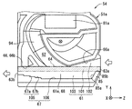
図1、図2に示すエアフロメータ10は、空気等の流体を対象として流量や温度、湿度、圧力等の物理量を計測する物理量計測装置である。エアフロメータ10は、例えばエンジン等の内燃機関11を有する車両に搭載されている。この内燃機関11は吸気通路12及び排気通路を有しており、エアフロメータ10は吸気通路12に取り付けられている。この場合、エアフロメータ10の計測対象である流体は、吸気通路12を流れる吸入空気とされる。この吸入空気は、内燃機関11の燃焼室に供給される気体である。なお、エアフロメータ10は、吸気通路12においてエアクリーナの下流側に配置されている。この場合、吸気通路12においてエアフロメータ10にとっては、エアクリーナ側が上流側であり、燃焼室側が下流側になる。
(First Embodiment)
The air flow meter 10 shown in FIGS. 1 and 2 is a physical quantity measuring device that measures physical quantities such as flow rate, temperature, humidity, and pressure for a fluid such as air. The air flow meter 10 is mounted on a vehicle having an internal combustion engine 11 such as an engine. The internal combustion engine 11 has an intake passage 12 and an exhaust passage, and an air flow meter 10 is attached to the intake passage 12. In this case, the fluid to be measured by the air flow meter 10 is the intake air flowing through the intake passage 12. This intake air is a gas supplied to the combustion chamber of the internal combustion engine 11. The air flow meter 10 is arranged on the downstream side of the air cleaner in the intake passage 12. In this case, in the intake passage 12, the air cleaner side is the upstream side and the combustion chamber side is the downstream side for the air flow meter 10.
エアフロメータ10は、吸気通路12を形成する吸気管12aに着脱可能に取り付けられている。エアフロメータ10は、吸気管12aの筒壁を貫通するよう形成されたセンサ挿入孔12bに挿し込まれており、少なくとも一部を吸気通路12内に位置させている。吸気管12aは、センサ挿入孔12bから外周側に向けて延びたフランジ部12cを有している。フランジ部12cは、センサ挿入孔12bの周縁部に沿って延びており、例えば円環状になっている。フランジ部12cの先端面は、フランジ部12cの中心線に直交する方向に延びている。この場合、フランジ部12cの先端面は、吸気通路12の長手方向、すなわち吸気通路12において吸入空気が流れる方向に延びている。
The air flow meter 10 is detachably attached to an intake pipe 12a forming an intake passage 12. The air flow meter 10 is inserted into a sensor insertion hole 12b formed so as to penetrate the cylinder wall of the intake pipe 12a, and at least a part thereof is positioned in the intake passage 12. The intake pipe 12a has a flange portion 12c extending from the sensor insertion hole 12b toward the outer peripheral side. The flange portion 12c extends along the peripheral edge portion of the sensor insertion hole 12b, and has an annular shape, for example. The tip surface of the flange portion 12c extends in a direction orthogonal to the center line of the flange portion 12c. In this case, the tip surface of the flange portion 12c extends in the longitudinal direction of the intake passage 12, that is, in the direction in which the intake air flows in the intake passage 12.
エアフロメータ10は、ハウジング21及び流量検出部22を有している。ハウジング21は、例えば樹脂材料等によって形成されている。エアフロメータ10においては、ハウジング21が吸気管12aに取り付けられていることで、流量検出部22が、吸気通路12を流れる吸入空気と接触可能な状態になる。ハウジング21は、流路形成部24、嵌合部25、Oリング26、フランジ部27及びコネクタ部28を有している。
The air flow meter 10 has a housing 21 and a flow rate detecting unit 22. The housing 21 is made of, for example, a resin material. In the air flow meter 10, the housing 21 is attached to the intake pipe 12a so that the flow rate detecting unit 22 can come into contact with the intake air flowing through the intake passage 12. The housing 21 has a flow path forming portion 24, a fitting portion 25, an O-ring 26, a flange portion 27, and a connector portion 28.
流路形成部24は流路31,32を形成している。流路31,32は、流路形成部24の内部空間により形成されており、吸気通路12を流れる吸入空気の一部をハウジング21の内部に導入する。通過流路31は、流路形成部24を貫通しており、通過流路31の上流端部を流入口33aと称し、下流側端部を流出口33bと称する。計測流路32は、通過流路31の中間部分から分岐した分岐流路であり、湾曲した部分を有していることで流路形成部24の内部を周回している。ただし、計測流路32は、1周はしておらず、計測流路32の上流端部寄りの部分と下流端部寄りの部分とが流路形成部24の幅方向には重複していない。また、通過流路31と計測流路32とについても、流路形成部24の幅方向には重複していない。
The flow path forming portion 24 forms the flow paths 31 and 32. The flow paths 31 and 32 are formed by the internal space of the flow path forming portion 24, and a part of the intake air flowing through the intake passage 12 is introduced into the housing 21. The passing flow path 31 penetrates the flow path forming portion 24, and the upstream end of the passing flow path 31 is referred to as an inflow port 33a, and the downstream end is referred to as an outflow port 33b. The measurement flow path 32 is a branch flow path branched from the intermediate portion of the pass flow path 31, and has a curved portion so as to go around the inside of the flow path forming portion 24. However, the measurement flow path 32 does not make one round, and the portion of the measurement flow path 32 near the upstream end and the portion near the downstream end do not overlap in the width direction of the flow path forming portion 24. .. Further, the passing flow path 31 and the measuring flow path 32 do not overlap in the width direction of the flow path forming portion 24.
計測流路32の下流側端部は、通過流路31の下流側端部と同様に開放されており、この下流側端部を計測出口33cと称する。計測流路32は、下流端部に向けて分岐していることで計測出口33cを2つ有しており、これら計測出口33cは、流路形成部24の幅方向において互いに離間した位置に横並びに配置されている。上述したように、通過流路31と計測流路32とが流路形成部24の幅方向には重複していないことに起因して、各計測出口33cと流出口33bとについても、流路形成部24の幅方向には重複していない。なお、吸気通路12を主通路と称し、通過流路31及び計測流路32をまとめて副通路と称することもできる。また、計測出口33cが分岐出口に相当する。
The downstream end of the measuring flow path 32 is open in the same manner as the downstream end of the passing flow path 31, and this downstream end is referred to as a measurement outlet 33c. The measurement flow path 32 has two measurement outlets 33c because it branches toward the downstream end, and these measurement outlets 33c are arranged side by side at positions separated from each other in the width direction of the flow path forming portion 24. Is located in. As described above, since the passing flow path 31 and the measuring flow path 32 do not overlap in the width direction of the flow path forming portion 24, the flow paths of the measuring outlets 33c and the outflow port 33b are also changed. There is no overlap in the width direction of the forming portion 24. The intake passage 12 may be referred to as a main passage, and the passage passage 31 and the measurement passage 32 may be collectively referred to as a sub passage. Further, the measurement outlet 33c corresponds to the branch outlet.
嵌合部25は、センサ挿入孔12bにOリング26を介して内嵌される部位である。Oリング26は、吸気通路12と吸気管12aの外部とをシールする部材である。Oリング26は、嵌合部25に外嵌されており、フランジ部12cの内周側に入り込んだ状態で嵌合部25とセンサ挿入孔12bとの間に介在している。フランジ部27は、嵌合部25を挟んで流路形成部24とは反対側に配置されており、センサ挿入孔12bを吸気管12aの外周側から覆っている。また、フランジ部27は、吸気管12aのフランジ部12cの先端部に引っ掛かることで、ハウジング21が吸気通路12内に入り込み過ぎることを規制する。フランジ部27は、流路形成部24側を向いたフランジ面27aを有している。このフランジ面27aは、フランジ部12cの先端面に平行に延びており、フランジ部12cの先端面に重ねられている。
The fitting portion 25 is a portion that is internally fitted into the sensor insertion hole 12b via the O-ring 26. The O-ring 26 is a member that seals the intake passage 12 and the outside of the intake pipe 12a. The O-ring 26 is fitted outside the fitting portion 25, and is interposed between the fitting portion 25 and the sensor insertion hole 12b in a state where the O-ring 26 is inserted into the inner peripheral side of the flange portion 12c. The flange portion 27 is arranged on the side opposite to the flow path forming portion 24 with the fitting portion 25 interposed therebetween, and covers the sensor insertion hole 12b from the outer peripheral side of the intake pipe 12a. Further, the flange portion 27 is caught by the tip end portion of the flange portion 12c of the intake pipe 12a to prevent the housing 21 from entering the intake passage 12 too much. The flange portion 27 has a flange surface 27a facing the flow path forming portion 24 side. The flange surface 27a extends parallel to the tip surface of the flange portion 12c and overlaps the tip surface of the flange portion 12c.
コネクタ部28は、複数の端子を囲う部位である。コネクタ部28には、プラグ部が挿入される。プラグ部は、ECU等の機関制御装置に直接的又は間接的に電気接続された接続線の端部に設けられており、コネクタ部28と嵌合する。
The connector portion 28 is a portion that surrounds a plurality of terminals. A plug portion is inserted into the connector portion 28. The plug portion is provided at the end of a connection line that is directly or indirectly electrically connected to an engine control device such as an ECU, and fits with the connector portion 28.
流量検出部22は、例えば発熱抵抗体等の発熱部やヒータ部を用いた熱式の流量センサであり、流量検出部22の検出面はメンブレンにより形成されている。流量検出部22は、計測流路32の中間位置に配置されている。ハウジング21が吸気管12aに取り付けられることで、流量検出部22には、計測流路32を流通する吸入空気が供給される。流量検出部22は、コネクタ部28に設けられた複数の端子と電気的に接続されている。流量検出部22は、吸気流量に対応したセンサ信号であって、計測流路32を流れる空気の流速に対応したセンサ信号を、流量信号として機関制御装置に対して出力する。流量検出部22は、計測流路32を流れる吸入空気の流量を検出することで、吸気通路12を流れる吸入空気の流量を検出することになる。なお、流量検出部22は、吸入空気の流量を物理量として検出する物理量検出部に相当する。また、流量検出部22は、熱式の流量センサに限定されず、可動フラップ式の流量センサやカルマン渦式の流量センサ等であってもよい。
The flow rate detection unit 22 is a thermal type flow rate sensor that uses, for example, a heat generation unit such as a heat generation resistor or a heater unit, and the detection surface of the flow rate detection unit 22 is formed of a membrane. The flow rate detection unit 22 is arranged at an intermediate position of the measurement flow path 32. By attaching the housing 21 to the intake pipe 12a, the flow rate detecting unit 22 is supplied with the intake air flowing through the measurement flow path 32. The flow rate detection unit 22 is electrically connected to a plurality of terminals provided on the connector unit 28. The flow rate detection unit 22 outputs a sensor signal corresponding to the intake flow rate and a sensor signal corresponding to the flow velocity of the air flowing through the measurement flow path 32 to the engine control device as a flow rate signal. The flow rate detection unit 22 detects the flow rate of the intake air flowing through the intake passage 12 by detecting the flow rate of the intake air flowing through the measurement flow path 32. The flow rate detection unit 22 corresponds to a physical quantity detection unit that detects the flow rate of intake air as a physical quantity. Further, the flow rate detection unit 22 is not limited to the thermal type flow rate sensor, and may be a movable flap type flow rate sensor, a Karman vortex type flow rate sensor, or the like.
エアフロメータ10は、流量検出部22の他にも、温度を検出する温度検出部や、湿度を検出する湿度検出部を有している。温度検出部や湿度検出部は、ハウジング21の外周側に設けられており、吸気通路12を流れる吸入空気の温度や湿度に応じたセンサ信号を温度信号や湿度信号として出力する。例えば、エアフロメータ10は、ハウジング21の外周側においてこれら検出部を支持する支持体を有しており、この支持体がハウジング21に固定されている。
In addition to the flow rate detection unit 22, the air flow meter 10 has a temperature detection unit that detects temperature and a humidity detection unit that detects humidity. The temperature detection unit and the humidity detection unit are provided on the outer peripheral side of the housing 21, and output sensor signals according to the temperature and humidity of the intake air flowing through the intake passage 12 as temperature signals and humidity signals. For example, the air flow meter 10 has a support that supports these detection portions on the outer peripheral side of the housing 21, and the support is fixed to the housing 21.
エアフロメータ10については、2つの計測出口33cが並ぶ方向を幅方向Xと称し、流路形成部24とフランジ部27とが並ぶ方向を高さ方向Yと称し、通過流路31が延びる方向を奥行き方向Zと称する。これら幅方向X、高さ方向Y及び奥行き方向Zは互いに直交しており、フランジ部27のフランジ面27aが幅方向X及び奥行き方向Zの両方に平行に延びている。エアフロメータ10が、吸気管12aに取り付けられた状態では、流入口33aが吸気通路12の上流側を向き、流出口33b及び計測出口33cが下流側を向いている。この場合、吸気通路12において吸入空気が流れる方向が奥行き方向Zになり、流入口33aからの流入空気の流入向きが奥行き方向Zと同じになりやすいと考えられる。エアフロメータ10においては、流入口33aから流入した吸入空気が、通過流路31や計測流路32を通過することで流出口33b及び各計測出口33cのそれぞれから流出する。
Regarding the air flow meter 10, the direction in which the two measurement outlets 33c are lined up is referred to as the width direction X, the direction in which the flow path forming portion 24 and the flange portion 27 are lined up is referred to as the height direction Y, and the direction in which the passing flow path 31 extends is referred to as the height direction Y. It is called the depth direction Z. The width direction X, the height direction Y, and the depth direction Z are orthogonal to each other, and the flange surface 27a of the flange portion 27 extends parallel to both the width direction X and the depth direction Z. When the air flow meter 10 is attached to the intake pipe 12a, the inflow port 33a faces the upstream side of the intake passage 12, and the outflow port 33b and the measurement outlet 33c face the downstream side. In this case, it is considered that the direction in which the intake air flows in the intake passage 12 is the depth direction Z, and the inflow direction of the inflow air from the inflow port 33a is likely to be the same as the depth direction Z. In the air flow meter 10, the intake air flowing in from the inflow port 33a flows out from each of the outflow port 33b and each measurement outlet 33c by passing through the passing flow path 31 and the measuring flow path 32.
通過流路31と計測流路32との境界である流路境界部34においては、通過流路31の中間部分が高さ方向Yにおいてフランジ部27側に向けて開放されている。流路境界部34においては、通過流路31の中間部分と計測流路32の上流端部とが接続されており、計測流路32の上流端部を計測入口と称することもできる。計測流路32は、流路境界部34と計測出口33cとの間において奥行き方向Zに延びた部分を有しており、この部分に流量検出部22が配置されている。
In the flow path boundary portion 34, which is the boundary between the passing flow path 31 and the measuring flow path 32, the intermediate portion of the passing flow path 31 is opened toward the flange portion 27 in the height direction Y. In the flow path boundary portion 34, the intermediate portion of the passing flow path 31 and the upstream end portion of the measurement flow path 32 are connected, and the upstream end portion of the measurement flow path 32 can also be referred to as a measurement inlet. The measurement flow path 32 has a portion extending in the depth direction Z between the flow path boundary portion 34 and the measurement outlet 33c, and the flow rate detection unit 22 is arranged in this portion.
エアフロメータ10においては、吸入空気と共に砂やゴミ等のダストが異物として流入口33aから進入することが想定される。この場合、異物の多くは吸入空気の流れに沿って奥行き方向Zに進行することで流出口33bから出て行くが、一部の吸入空気と共に計測流路32に進入する異物もある、と考えられる。特に、質量の比較的大きな異物や比較的大型の異物など大異物については、吸入空気の流れ向きに関係なく直進しやすいと考えられる。このため、大異物については、通過流路31の内周面31aに衝突して跳ね返り、進行方向が変わることで却って計測流路32に進入しやすくなる、ということが懸念される。
In the air flow meter 10, it is assumed that dust such as sand and dust enters from the inflow port 33a as foreign matter together with the intake air. In this case, most of the foreign matter goes out from the outlet 33b by traveling in the depth direction Z along the flow of the intake air, but it is considered that some foreign matter enters the measurement flow path 32 together with some intake air. Be done. In particular, it is considered that large foreign substances such as foreign substances having a relatively large mass and foreign substances having a relatively large mass tend to go straight regardless of the flow direction of the intake air. Therefore, there is a concern that a large foreign matter may collide with the inner peripheral surface 31a of the passing flow path 31 and bounce off, and the traveling direction may change, so that the large foreign matter may rather easily enter the measuring flow path 32.
これに対して、本実施形態では、通過流路31の内周面31aにて跳ね返った大異物が計測流路32に進入することが抑制されるようになっている。なお、質量の比較的小さな異物や比較的小型の異物など小異物は、吸入空気の流れに合わせて進行方向が変化しやすく、通過流路31の内周面31aに衝突する前に曲がりやすい、と考えられる。
On the other hand, in the present embodiment, the large foreign matter bounced off the inner peripheral surface 31a of the passing flow path 31 is suppressed from entering the measuring flow path 32. It should be noted that small foreign matter such as a relatively small foreign matter or a relatively small foreign matter easily changes its traveling direction according to the flow of the intake air and easily bends before colliding with the inner peripheral surface 31a of the passing flow path 31. it is conceivable that.
図1、図3に示すように、通過流路31の内周面31aは、天井面36、床面37及び一対の壁面38を有している。一対の壁面38は、幅方向Xにおいて流路境界部34や流入口33a及び流出口33bを挟んで互いに対向する一対の対向面になっており、天井面36と床面37とは、壁面38を挟んで対向する一対の対向面になっている。通過流路31においては、天井面36の一部が開放されており、この開放された部分に計測流路32の上流端部が接続されることで流路境界部34が形成されている。天井面36は、流入口33aと流路境界部34との間の流入天井面部36aと、流路境界部34と流出口33bとの間の流出天井面部36bとを有している。
As shown in FIGS. 1 and 3, the inner peripheral surface 31a of the passing flow path 31 has a ceiling surface 36, a floor surface 37, and a pair of wall surfaces 38. The pair of wall surfaces 38 are a pair of facing surfaces facing each other with the flow path boundary portion 34, the inflow port 33a, and the outflow port 33b interposed therebetween in the width direction X, and the ceiling surface 36 and the floor surface 37 are the wall surface 38. It is a pair of facing surfaces facing each other with a. In the passage flow path 31, a part of the ceiling surface 36 is open, and the flow path boundary portion 34 is formed by connecting the upstream end portion of the measurement flow path 32 to the open portion. The ceiling surface 36 has an inflow ceiling surface portion 36a between the inflow port 33a and the flow path boundary portion 34, and an outflow ceiling surface portion 36b between the flow path boundary portion 34 and the outflow port 33b.
ここで、流路境界部34は、最も上流側にある上流境界部分34aと、最も下流側にある下流境界部分34bとを有しており、高さ方向Yにおいては、上流境界部分34aが下流境界部分34bよりもフランジ部27から離間した位置にある。この場合、計測流路32の上流端部が流入口33a側ではなく流出口33b側に向けて開放された状態になっている。このため、奥行き方向Zに直進している異物が流入口33aから進入したとしても、この異物がこのまま計測流路32に進入するということが生じにくくなっている。なお、この構成では、例えば人が奥行き方向Zにおいて流入口33aから通過流路31内を覗き込んだとしても、計測流路32の上流端部を視認できないことになる。
Here, the flow path boundary portion 34 has an upstream boundary portion 34a on the most upstream side and a downstream boundary portion 34b on the most downstream side, and the upstream boundary portion 34a is downstream in the height direction Y. It is located at a position separated from the flange portion 27 from the boundary portion 34b. In this case, the upstream end of the measurement flow path 32 is open toward the outlet 33b side instead of the inlet 33a side. Therefore, even if a foreign matter traveling straight in the depth direction Z enters from the inflow port 33a, it is unlikely that the foreign matter enters the measurement flow path 32 as it is. In this configuration, for example, even if a person looks into the passing flow path 31 from the inflow port 33a in the depth direction Z, the upstream end portion of the measuring flow path 32 cannot be visually recognized.
天井面36においては、流入天井面部36a及び流出天井面部36bが段差面41a,41b及び接続面42a,42bをそれぞれ有していることで、流入口33a側を向いた段差が形成されている。流入段差面41aは、流入天井面部36aにおいて流入口33aと流路境界部34との並び方向に沿って奥行き間隔Daで複数並べられている。流出段差面41bは、流出天井面部36bにおいて流路境界部34と流出口33bとの並び方向に沿って奥行き間隔Dbで複数並べられており、奥行き間隔Dbは奥行き間隔Daより小さい。これら段差面41a,41bは、天井面36において床面37に向けて延びていることで流入口33a側を向いており、一対の壁面38にかけ渡された状態になっている。各流入段差面41a及び各流出段差面41bは、互いに同じ向きに延びており、具体的には、いずれも奥行き方向Zに直交する方向に延びている。
In the ceiling surface 36, the inflow ceiling surface portion 36a and the outflow ceiling surface portion 36b have the stepped surfaces 41a and 41b and the connecting surfaces 42a and 42b, respectively, so that a step facing the inflow port 33a side is formed. A plurality of inflow step surfaces 41a are arranged at a depth interval Da along the arrangement direction of the inflow port 33a and the flow path boundary portion 34 on the inflow ceiling surface portion 36a. A plurality of outflow step surfaces 41b are arranged in the outflow ceiling surface portion 36b at a depth interval Db along the arrangement direction of the flow path boundary portion 34 and the outflow port 33b, and the depth interval Db is smaller than the depth interval Da. These stepped surfaces 41a and 41b are oriented toward the inflow port 33a by extending toward the floor surface 37 on the ceiling surface 36, and are in a state of being spread over the pair of wall surfaces 38. Each inflow step surface 41a and each outflow step surface 41b extend in the same direction as each other, and specifically, both extend in a direction orthogonal to the depth direction Z.
流入接続面42aは、流入天井面部36aにおいて、隣り合う流入段差面41aのうち、上流側の流入段差面41aの下流側端部と下流側の流入段差面41aの上流端部とを接続しており、流入段差面41aの数に応じて複数設けられている。流出接続面42bは、流出天井面部36bにおいて、隣り合う流出段差面41bのうち、上流側の流出段差面41bの下流側端部と下流側の流出段差面41bの上流端部とを接続しており、流出段差面41bの数に応じて複数設けられている。これら接続面42a,42bは、互いに同じ向きに延びており、具体的には、いずれも高さ方向Yに直交する方向に延びている。すなわち、各流入接続面42aは流入段差面41aに直交し、各流出接続面42bは流出段差面41bに直交している。この場合、奥行き方向Zにおいて、接続面42a,42bの奥行き寸法は、隣り合う段差面41a,41bの奥行き間隔Da,Dbと同じになっている。
The inflow connection surface 42a connects the downstream end of the inflow step surface 41a on the upstream side and the upstream end of the inflow step surface 41a on the downstream side of the adjacent inflow step surfaces 41a on the inflow ceiling surface portion 36a. A plurality of them are provided according to the number of inflow step surfaces 41a. The outflow connection surface 42b connects the downstream end of the outflow step surface 41b on the upstream side and the upstream end of the outflow step surface 41b on the downstream side of the adjacent outflow step surfaces 41b on the outflow ceiling surface portion 36b. A plurality of the outflow step surfaces 41b are provided according to the number of the outflow step surfaces 41b. These connecting surfaces 42a and 42b extend in the same direction as each other, and specifically, both extend in a direction orthogonal to the height direction Y. That is, each inflow connection surface 42a is orthogonal to the inflow step surface 41a, and each outflow connection surface 42b is orthogonal to the outflow step surface 41b. In this case, in the depth direction Z, the depth dimensions of the connecting surfaces 42a and 42b are the same as the depth intervals Da and Db of the adjacent step surfaces 41a and 41b.
流入天井面部36a及び流出天井面部36bは、段差面41a,41b及び接続面42a,42aにより全体として階段状になっている。流入天井面部36aにおいては、下流側に向かうにつれて段差が徐々に大きくなっている。具体的には、各段差において奥行き間隔Daは均一である一方で、高さ方向Yにおける流入段差面41aの高さ寸法Haが流入口33aから遠ざかるにつれて徐々に大きくなっている。流入口33aに近い段差では、高さ寸法Haが奥行き間隔Daより小さいが、流路境界部34に近付くにつれて徐々に高さ寸法Haと奥行き間隔Daとの差異が小さくなり、流路境界部34に近い段差では高さ寸法Haと奥行き間隔Daとがほぼ同じ値になっている。なお、高さ寸法Haは奥行き間隔Daより小さくなっていてもよい。
The inflow ceiling surface portion 36a and the outflow ceiling surface portion 36b have a stepped shape as a whole due to the stepped surfaces 41a and 41b and the connecting surfaces 42a and 42a. In the inflow ceiling surface portion 36a, the step gradually increases toward the downstream side. Specifically, while the depth interval Da is uniform at each step, the height dimension Ha of the inflow step surface 41a in the height direction Y gradually increases as the distance from the inflow port 33a increases. At the step near the inflow port 33a, the height dimension Ha is smaller than the depth interval Da, but the difference between the height dimension Ha and the depth interval Da gradually becomes smaller as it approaches the flow path boundary portion 34, and the flow path boundary portion 34 At the step close to, the height dimension Ha and the depth interval Da have almost the same value. The height dimension Ha may be smaller than the depth interval Da.
一方、流出天井面部36bにおいては、下流側に向かうにつれて段差が徐々に小さくなっている。具体的には、各段差において奥行き間隔Dbは均一である一方で、高さ方向Yにおける流出段差面41bの高さ寸法Hbが流出口33bに近付くにつれて徐々に小さくなっている。流路境界部34に近い段差では、高さ寸法Hbが奥行き間隔Dbより大きいが、流出口33bに近付くにつれて徐々に高さ寸法Hbと奥行き間隔Dbとの差異が小さくなり、流出口33bに近い段差では高さ寸法Hbの方が奥行き間隔Dbより大きくなっている。
On the other hand, in the outflow ceiling surface portion 36b, the step gradually becomes smaller toward the downstream side. Specifically, while the depth interval Db is uniform at each step, the height dimension Hb of the outflow step surface 41b in the height direction Y gradually decreases as it approaches the outlet 33b. At the step near the flow path boundary portion 34, the height dimension Hb is larger than the depth interval Db, but the difference between the height dimension Hb and the depth interval Db gradually becomes smaller as it approaches the outlet 33b, and is closer to the outlet 33b. At the step, the height dimension Hb is larger than the depth interval Db.
天井面36においては、奥行き方向Zに対する流出天井面部36bの全体的な傾斜角度が、奥行き方向Zに対する流入天井面部36aの全体的な傾斜角度に比べて大きくなっている。ここでは、流入天井面部36aの上流端部と下流端部との位置関係について、高さ方向Yの離間距離を高さ距離Hayと称し、奥行き方向Zの離間距離を奥行き距離Dazと称する。また、流入天井面部36aの上流端部と下流端部との位置関係について、高さ方向Yの離間距離を高さ距離Hbyと称し、奥行き方向Zの離間距離を奥行き距離Dazと称する。この場合、流出天井面部36bの傾き度合いを示すHby/Dbzの値が、流入天井面部36aの傾き度合いを示すHay/Dazの値より大きくなっている。これにより、流入口33aから吸入空気が流入しやすく、且つ計測流路32での吸入空気の流速が大きくなりやすくなっている。
On the ceiling surface 36, the overall inclination angle of the outflow ceiling surface portion 36b with respect to the depth direction Z is larger than the overall inclination angle of the inflow ceiling surface portion 36a with respect to the depth direction Z. Here, regarding the positional relationship between the upstream end portion and the downstream end portion of the inflow ceiling surface portion 36a, the separation distance in the height direction Y is referred to as the height distance Hay, and the separation distance in the depth direction Z is referred to as the depth distance Daz. Further, regarding the positional relationship between the upstream end portion and the downstream end portion of the inflow ceiling surface portion 36a, the separation distance in the height direction Y is referred to as the height distance Hby, and the separation distance in the depth direction Z is referred to as the depth distance Daz. In this case, the value of Hby / Dbz indicating the degree of inclination of the outflow ceiling surface portion 36b is larger than the value of Hay / Daz indicating the degree of inclination of the inflow ceiling surface portion 36a. As a result, the intake air tends to flow in from the inflow port 33a, and the flow velocity of the intake air in the measurement flow path 32 tends to increase.
流入天井面部36aは、流入口33aの形状に合わせて、幅方向Xの中間部分がフランジ部27側に向けて膨らむように湾曲している。この場合、流入段差面41aについては、上流端部及び下流側端部の両方が湾曲している。流入接続面42aは、隣り合う流入段差面41aを接続できるように湾曲している。一方、流出口33bはほぼ矩形状になっており、流出天井面部36bは湾曲していない。
The inflow ceiling surface portion 36a is curved so that the intermediate portion in the width direction X bulges toward the flange portion 27 side according to the shape of the inflow port 33a. In this case, with respect to the inflow step surface 41a, both the upstream end portion and the downstream side end portion are curved. The inflow connection surface 42a is curved so that adjacent inflow step surfaces 41a can be connected. On the other hand, the outflow port 33b has a substantially rectangular shape, and the outflow ceiling surface portion 36b is not curved.
ここまで説明した本実施形態によれば、流入天井面部36aが流入段差面41aを有しているため、流入口33aから進入した異物が計測流路32に進入しにくくなっている。例えば、図3に実線で示すように、流入口33aから進入した大異物F1が奥行き方向Zに直進して流入天井面部36aの流入段差面41aに衝突した場合、大異物F1は、自身の軌跡を辿るようにして流入口33a側に戻る可能性が高くなっている。このように、大異物F1は、通過流路31において流入天井面部36aの流入段差面41aに衝突することで下流側に進みにくくなり、計測流路32に進入しにくくなる。
According to the present embodiment described so far, since the inflow ceiling surface portion 36a has the inflow step surface 41a, it is difficult for foreign matter that has entered from the inflow port 33a to enter the measurement flow path 32. For example, as shown by the solid line in FIG. 3, when the large foreign matter F1 entering from the inflow port 33a goes straight in the depth direction Z and collides with the inflow step surface 41a of the inflow ceiling surface portion 36a, the large foreign matter F1 has its own trajectory. There is a high possibility of returning to the inflow port 33a side by following. As described above, the large foreign matter F1 collides with the inflow step surface 41a of the inflow ceiling surface portion 36a in the passing flow path 31, so that it becomes difficult to proceed to the downstream side and it becomes difficult to enter the measurement flow path 32.
これに対して、本実施形態とは異なり、例えば、図4に示すように流入天井面部36aが流入段差面41aを有していない構成では、この流入天井面部36aが奥行き方向Zに直交していない。このため、大異物F1は、全体として傾斜している流入天井面部36aに衝突し、進行方向を変えつつも下流側に進むことが考えられる。この場合、大異物F1が流入天井面部36aにて跳ね返った角度によっては、図4に実線で示すように、大異物F1が流入天井面部36aに続いて床面37で跳ね返りつつ下流側に進むことで計測流路32に進入しやすくなってしまう、ということが懸念される。このように、流入天井面部36aでの跳ね返りに伴って大異物F1の進行方向が高さ方向Yについて変わると、その大異物F1が計測流路32に流入する可能性が高くなりやすい。この点、本実施形態では、流入天井面部36aの流入段差面41aにて跳ね返った大異物F1の進行方向が高さ方向Yについて変わりにくい構成が実現されているため、その大異物F1が計測流路32に進入しやすくなることを抑制できる。
On the other hand, unlike the present embodiment, for example, in a configuration in which the inflow ceiling surface portion 36a does not have the inflow step surface 41a as shown in FIG. 4, the inflow ceiling surface portion 36a is orthogonal to the depth direction Z. Absent. Therefore, it is conceivable that the large foreign matter F1 collides with the inflow ceiling surface portion 36a which is inclined as a whole and advances to the downstream side while changing the traveling direction. In this case, depending on the angle at which the large foreign matter F1 bounces off the inflow ceiling surface 36a, as shown by the solid line in FIG. 4, the large foreign matter F1 rebounds on the floor surface 37 following the inflow ceiling surface 36a and proceeds to the downstream side. There is a concern that it will be easy to enter the measurement flow path 32. As described above, when the traveling direction of the large foreign matter F1 changes with respect to the height direction Y due to the bounce at the inflow ceiling surface portion 36a, the possibility that the large foreign matter F1 flows into the measurement flow path 32 tends to increase. In this respect, in the present embodiment, the large foreign matter F1 that bounces off the inflow step surface 41a of the inflow ceiling surface portion 36a is hard to change with respect to the height direction Y, so that the large foreign matter F1 is the measurement flow. It is possible to suppress the tendency to easily enter the road 32.
流量検出部22が計測流路32に設けられたエアフロメータ10では、計測流路32を流れる吸入空気の流速が小さ過ぎると流量検出部22の検出精度が低下するということが懸念される。これに対して、本実施形態によれば、複数の流入段差面41aが奥行き方向Zに並んでいるため、流入口33aの開放面積を極力大きくしつつ、通過流路31の断面積を流路境界部34に向けて段階的に小さくすることができる。このため、大異物が計測流路32に進入することを流入段差面41aにより抑制しつつ、計測流路32への吸入空気の流入量が不足することを抑制することができる。
In the air flow meter 10 in which the flow rate detection unit 22 is provided in the measurement flow path 32, there is a concern that the detection accuracy of the flow rate detection unit 22 will decrease if the flow velocity of the intake air flowing through the measurement flow path 32 is too small. On the other hand, according to the present embodiment, since the plurality of inflow step surfaces 41a are arranged in the depth direction Z, the cross-sectional area of the passing flow path 31 is changed while making the open area of the inflow port 33a as large as possible. It can be gradually reduced toward the boundary portion 34. Therefore, it is possible to prevent the large foreign matter from entering the measurement flow path 32 by the inflow step surface 41a, and to prevent the inflow amount of the intake air into the measurement flow path 32 from being insufficient.
本実施形態によれば、複数の流入段差面41aが流入天井面部36aに含まれているため、流入口33aから流路境界部34に近付くにつれて流入天井面部36aがフランジ部27から段階的に離間させることができる。この場合、例えば図3に示すように、流入口33aから流入した吸入空気GがY方向において流路境界部34から徐々に遠ざかりやすくなるため、大異物に加えて、吸入空気Gの流れに乗りやすい小異物についても、計測流路32に流れ込むことを抑制できる。
According to the present embodiment, since the plurality of inflow step surfaces 41a are included in the inflow ceiling surface portion 36a, the inflow ceiling surface portion 36a is gradually separated from the flange portion 27 as the inflow inlet 33a approaches the flow path boundary portion 34. Can be made to. In this case, for example, as shown in FIG. 3, the intake air G flowing in from the inflow port 33a tends to gradually move away from the flow path boundary portion 34 in the Y direction, so that the intake air G rides on the flow of the intake air G in addition to the large foreign matter. Even small foreign substances that are easy to flow into the measurement flow path 32 can be suppressed.
本実施形態によれば、通過流路31において、流路境界部34に近い流入段差面41aほど高さ寸法Haが大きくなっているため、流入口33aから流入した吸入空気の進行方向の変化率を徐々に大きくできる。この場合、吸入空気の進行方向の変化率が急激に大きくされた場合に比べて、渦流が発生するなどして吸入空気の流れが乱れるということが生じにくくなっている。このため、流れの乱れに伴って計測流路32に吸入空気が流れ込みにくくなって計測流路32での吸入空気の流速が不足するということや、流れの乱れに巻き込まれた異物が計測流路32に進入するということなどを抑制できる。
According to the present embodiment, in the passing flow path 31, the height dimension Ha becomes larger as the inflow step surface 41a closer to the flow path boundary portion 34, so that the rate of change in the traveling direction of the intake air flowing in from the inflow port 33a Can be gradually increased. In this case, it is less likely that the flow of the intake air is disturbed due to the generation of whirlpools, etc., as compared with the case where the rate of change in the traveling direction of the intake air is rapidly increased. For this reason, it becomes difficult for the intake air to flow into the measurement flow path 32 due to the turbulence of the flow, the flow velocity of the intake air in the measurement flow path 32 becomes insufficient, and foreign matter caught in the turbulence of the flow enters the measurement flow path. It is possible to suppress the entry into 32.
本実施形態によれば、流入接続面42aが奥行き方向Zと平行に延びている。このため、流入口33aから進入して奥行き方向Zに直進している異物が流入段差面41aに到達する際に流入接続面42aが異物にとって障害物になる、ということを抑制できる。
According to this embodiment, the inflow connection surface 42a extends parallel to the depth direction Z. Therefore, it is possible to prevent the inflow connection surface 42a from becoming an obstacle for the foreign matter when the foreign matter entering from the inflow port 33a and traveling straight in the depth direction Z reaches the inflow step surface 41a.
本実施形態によれば、流入段差面41aが高さ方向Yと平行に延びているため、流入口33aからの吸入空気の進入方向になりやすい奥行き方向Zに流入段差面41aが直交することになる。このため、流入段差面41aに衝突して跳ね返った異物が高さ方向Yに対して傾いた向きで下流側に進み、床面37に衝突して跳ね返るなどして計測流路32に進入する、ということを抑制できる。
According to the present embodiment, since the inflow step surface 41a extends parallel to the height direction Y, the inflow step surface 41a is orthogonal to the depth direction Z, which tends to be the inflow direction of the intake air from the inflow port 33a. Become. Therefore, the foreign matter that collides with the inflow step surface 41a and bounces off moves toward the downstream side in a direction inclined with respect to the height direction Y, collides with the floor surface 37 and bounces off, and enters the measurement flow path 32. That can be suppressed.
本実施形態によれば、流出天井面部36bが流出段差面41bを有しているため、流入口33aから進入して流路境界部34を通過した異物が計測流路32に進入しにくくなっている。例えば、図3に破線で示すように、流入口33aから進入した大異物F2が奥行き方向Zに直進して流出天井面部36bの流出段差面41bに衝突した場合、大異物F2は、自身の軌跡を辿るようにして流入口33a側に戻る可能性が高くなっている。このように、大異物F2は、通過流路31において流出天井面部36bの流出段差面41bに衝突することで、一度は通過した計測流路32を今度は逆向きに通過することになるが、計測流路32に進入しにくい角度で上流側に向けて進みやすくなる。
According to the present embodiment, since the outflow ceiling surface portion 36b has the outflow step surface 41b, it becomes difficult for foreign matter that has entered from the inflow port 33a and passed through the flow path boundary portion 34 to enter the measurement flow path 32. There is. For example, as shown by the broken line in FIG. 3, when the large foreign matter F2 that has entered from the inflow port 33a goes straight in the depth direction Z and collides with the outflow step surface 41b of the outflow ceiling surface portion 36b, the large foreign matter F2 has its own trajectory. There is a high possibility of returning to the inflow port 33a side by following. In this way, the large foreign matter F2 collides with the outflow step surface 41b of the outflow ceiling surface portion 36b in the passage flow path 31, and thus passes through the measurement flow path 32 once passed in the opposite direction. It becomes easy to proceed toward the upstream side at an angle that makes it difficult to enter the measurement flow path 32.
これに対して、本実施形態とは異なり、例えば、図4に示すように流出天井面部36bが流出段差面41bを有していない構成では、この流出天井面部36bが奥行き方向Zに直交していない。このため、大異物F2は、全体として傾斜している流出天井面部36bに衝突し、進行方向を変えて計測流路32に進入することが考えられる。具体的には、大異物F2が流出天井面部36bにて跳ね返った角度によっては、図4に破線で示すように、大異物F2が流出天井面部36bに続いて床面37で跳ね返りつつ上流側に進むことで計測流路32に進入しやすくなってしまう、ということが懸念される。このように、流出天井面部36bでの跳ね返りに伴って大異物F2の進行方向が高さ方向Yについて変わると、その大異物F2が計測流路32に流入する可能性が高くなりやすい。この点、本実施形態では、流出天井面部36bの流出段差面41bにて跳ね返った大異物F2の進行方向が高さ方向Yについて変わりにくい構成が実現されているため、その大異物F2が計測流路32に流入しやすくなることを抑制できる。
On the other hand, unlike the present embodiment, for example, in a configuration in which the outflow ceiling surface portion 36b does not have the outflow step surface 41b as shown in FIG. 4, the outflow ceiling surface portion 36b is orthogonal to the depth direction Z. Absent. Therefore, it is conceivable that the large foreign matter F2 collides with the outflow ceiling surface portion 36b that is inclined as a whole, changes the traveling direction, and enters the measurement flow path 32. Specifically, depending on the angle at which the large foreign matter F2 bounces off the outflow ceiling surface 36b, as shown by the broken line in FIG. 4, the large foreign matter F2 bounces off the floor 37 following the outflow ceiling surface 36b and moves upstream. There is a concern that the progress will make it easier to enter the measurement flow path 32. As described above, when the traveling direction of the large foreign matter F2 changes with respect to the height direction Y due to the bounce at the outflow ceiling surface portion 36b, the possibility that the large foreign matter F2 flows into the measurement flow path 32 tends to increase. In this respect, in the present embodiment, the large foreign matter F2 that bounces off the outflow step surface 41b of the outflow ceiling surface portion 36b is hard to change in the height direction Y, so that the large foreign matter F2 is the measurement flow. It is possible to prevent the vehicle from easily flowing into the road 32.
上述したように、エアフロメータ10では、計測流路32を流れる吸入空気の流速が小さ過ぎると流量検出部22の検出精度が低下するということが懸念される。これに対して、本実施形態によれば、流路境界部34よりも下流側において、通過流路31の断面積が流出段差面41bにより小さくされることで通過流路31が絞られている。この場合、通過流路31での吸入空気の圧力が適度に高くなることで計測流路32に吸入空気が流れ込みやすくなり、計測流路32での吸入空気の流速が適度に大きくなる。このため、流量検出部22の検出精度が低下することを流出段差面41bにより抑制できる。
As described above, in the air flow meter 10, if the flow velocity of the intake air flowing through the measurement flow path 32 is too small, there is a concern that the detection accuracy of the flow rate detection unit 22 will decrease. On the other hand, according to the present embodiment, the passing flow path 31 is narrowed down by reducing the cross-sectional area of the passing flow path 31 by the outflow step surface 41b on the downstream side of the flow path boundary portion 34. .. In this case, since the pressure of the intake air in the passing flow path 31 is appropriately increased, the intake air is likely to flow into the measurement flow path 32, and the flow velocity of the intake air in the measurement flow path 32 is appropriately increased. Therefore, the decrease in the detection accuracy of the flow rate detection unit 22 can be suppressed by the outflow step surface 41b.
本実施形態によれば、複数の流出段差面41bが流出天井面部36bに含まれているため、流路境界部34よりも下流側において、流出口33bに向けて通過流路31の絞り度合いを徐々に大きくすることができる。この場合、流出口33bに向けて通過流路31の絞り度合いが急激に大きくなっている構成に比べて、渦流が発生するなどして吸入空気の流れが乱れるということが生じにくくなっている。このため、流れの乱れに巻き込まれた異物が計測流路32に進入するということを抑制できる。
According to the present embodiment, since a plurality of outflow stepped surfaces 41b are included in the outflow ceiling surface portion 36b, the degree of narrowing of the passing flow path 31 toward the outflow port 33b is reduced on the downstream side of the flow path boundary portion 34. It can be gradually increased. In this case, it is less likely that the flow of the intake air is disturbed due to the generation of whirlpools, etc., as compared with the configuration in which the degree of throttle of the passing flow path 31 is sharply increased toward the outlet 33b. Therefore, it is possible to prevent foreign matter caught in the turbulence of the flow from entering the measurement flow path 32.
本実施形態によれば、流出口33bに近い流出段差面41bほど高さ寸法Hbが小さくなっている。このため、通過流路31において流路境界部34周辺の領域を高さ方向Yについて極力大きくすることができる。これにより、吸入空気が通過流路31から計測流路32に流入しやすい状況をつくり出しつつ、流出口33bに向けて通過流路31を流出段差面41bにより徐々に絞る構成を実現できる。
According to this embodiment, the height dimension Hb becomes smaller as the outflow step surface 41b closer to the outflow port 33b. Therefore, in the passing flow path 31, the area around the flow path boundary portion 34 can be made as large as possible in the height direction Y. As a result, it is possible to realize a configuration in which the passing flow path 31 is gradually throttled by the outflow step surface 41b toward the outflow port 33b while creating a situation in which the intake air easily flows into the measurement flow path 32 from the passing flow path 31.
本実施形態によれば、流出接続面42bが奥行き方向Zと平行に延びている。このため、流路境界部34を通り過ぎて流出口33bに向かって奥行き方向Zに直進している異物が流出段差面41bに到達する際に流出接続面42bが異物にとって障害物になる、ということを抑制できる。
According to this embodiment, the outflow connection surface 42b extends parallel to the depth direction Z. Therefore, when the foreign matter passing straight through the flow path boundary portion 34 and traveling straight in the depth direction Z toward the outflow port 33b reaches the outflow step surface 41b, the outflow connecting surface 42b becomes an obstacle for the foreign matter. Can be suppressed.
本実施形態によれば、流出段差面41bが高さ方向Yと平行に延びているため、流入口33aからの吸入空気の進行方向になりやすい奥行き方向Zに流出段差面41bが直交することになる。このため、流出段差面41bに衝突して跳ね返った異物が高さ方向Yに対して傾いた向きで上流側に逆流して進み、床面37に衝突して跳ね返るなどして計測流路32に進入する、ということを抑制できる。
According to the present embodiment, since the outflow step surface 41b extends parallel to the height direction Y, the outflow step surface 41b is orthogonal to the depth direction Z, which tends to be the traveling direction of the intake air from the inflow port 33a. Become. For this reason, the foreign matter that collides with the outflow step surface 41b and bounces off flows back to the upstream side in a direction inclined with respect to the height direction Y, collides with the floor surface 37, and rebounds to the measurement flow path 32. It is possible to suppress the entry.
第1実施形態について、本開示の要旨を逸脱しない範囲内において種々の実施形態及び組み合わせに適用することができる。
The first embodiment can be applied to various embodiments and combinations without departing from the gist of the present disclosure.
変形例A1として、流入段差面41aにおいて、上流端部及び下流端部のうち一方だけが流入口33aの形状に合わせて湾曲していてもよく、両方とも湾曲していなくてもよい。また、流入天井面部36aは、流入口33aの形状に関係なく、湾曲していてもよく、湾曲していなくてもよい。例えば、流入口33aが矩形状の場合に、流入段差面41aや流入接続面42aが湾曲していてもよい。
As a modification A1, only one of the upstream end portion and the downstream end portion of the inflow step surface 41a may be curved according to the shape of the inflow port 33a, or both may not be curved. Further, the inflow ceiling surface portion 36a may or may not be curved regardless of the shape of the inflow port 33a. For example, when the inflow port 33a is rectangular, the inflow step surface 41a and the inflow connection surface 42a may be curved.
変形例A2として、流出口33bが矩形状でなくてもよい。この場合、流出段差面41b及び流出接続面42bが流出口33bの形状に合わせて外側や内側に向けて湾曲していてもよい。
As a modification A2, the outlet 33b does not have to be rectangular. In this case, the outflow step surface 41b and the outflow connection surface 42b may be curved outward or inward according to the shape of the outflow port 33b.
(第2実施形態)
上記第1実施形態のエアフロメータ10では、通過流路31と計測流路32とが幅方向Xに重複していなかったが、第2実施形態のエアフロメータでは、通過流路と計測流路とが幅方向Xに重複している。第2実施形態では、第1実施形態との相違点を中心に説明する。
(Second Embodiment)
In the air flow meter 10 of the first embodiment, the passing flow path 31 and the measuring flow path 32 did not overlap in the width direction X, but in the air flow meter of the second embodiment, the passing flow path and the measuring flow path Overlaps in the width direction X. In the second embodiment, the differences from the first embodiment will be mainly described.
図5〜図8に示すエアフロメータ50は、上記第1実施形態のエアフロメータ10と同様に、吸気管12aに取り付けられた状態で吸気通路12にて吸入空気の物理量を検出する物理量検出装置である。エアフロメータ50は、ハウジング51及び流量検出部52を有しており、ハウジング51は、流路形成部54、Oリング56、フランジ部57、フランジ面57a及びコネクタ部58を有している。これら部材や部位は、上記第1実施形態の同じ名称の部材や部位に対応している。
The air flow meter 50 shown in FIGS. 5 to 8 is a physical quantity detecting device that detects the physical quantity of intake air in the intake passage 12 in a state of being attached to the intake pipe 12a, similarly to the air flow meter 10 of the first embodiment. is there. The air flow meter 50 has a housing 51 and a flow rate detecting unit 52, and the housing 51 has a flow path forming unit 54, an O-ring 56, a flange portion 57, a flange surface 57a, and a connector portion 58. These members and parts correspond to the members and parts having the same name in the first embodiment.
なお、本実施形態のOリング56は、フランジ部12cの内周側には入り込んでおらず、フランジ部12cの先端部とフランジ部57との間に挟み込まれた状態になっている。この場合、フランジ面57aは、Oリング56を介してフランジ部12cの先端面に対向している。
The O-ring 56 of the present embodiment does not enter the inner peripheral side of the flange portion 12c, but is sandwiched between the tip portion of the flange portion 12c and the flange portion 57. In this case, the flange surface 57a faces the tip surface of the flange portion 12c via the O-ring 56.
ハウジング51においては、ハウジング本体51a、表カバー51b及び裏カバー51cにより流路形成部54が形成されている。ハウジング本体51aは、高さ方向Yにおいてフランジ部57から延びており、表カバー51b及び裏カバー51cは、幅方向Xにおいてハウジング本体51aを挟んで平行に対向した状態で、ハウジング本体51aに取り付けられている。ハウジング本体51a及びフランジ部57は、いずれも合成樹脂材料をモールド成形することなどにより一体的に形成されている。また、表カバー51b及び裏カバー51cも合成樹脂材料により形成されている。
In the housing 51, the flow path forming portion 54 is formed by the housing main body 51a, the front cover 51b, and the back cover 51c. The housing body 51a extends from the flange portion 57 in the height direction Y, and the front cover 51b and the back cover 51c are attached to the housing body 51a in a state where they face each other in parallel with the housing body 51a sandwiched in the width direction X. ing. Both the housing body 51a and the flange portion 57 are integrally formed by molding a synthetic resin material or the like. The front cover 51b and the back cover 51c are also made of a synthetic resin material.
流路形成部54は、通過流路61及び計測流路62を有しており、通過流路61は、流入口63a、流出口63b、計測出口63c、流路境界部64、上流境界部分64a及び下流境界部分64bを有している。通過流路61の内周面61aは、通過天井面66、流入天井面部66a、流出天井面部66b、通過床面67、通過壁面68、流入段差面71a、流入接続面72aを有している。これら部材や部位は、上記第1実施形態の同じ名称の部材や部位に対応している。なお、本実施形態では、通過床面67が奥行き方向Zに平行に延びている。
The flow path forming portion 54 has a passing flow path 61 and a measuring flow path 62, and the passing flow path 61 includes an inflow port 63a, an outflow port 63b, a measurement outlet 63c, a flow path boundary portion 64, and an upstream boundary portion 64a. And has a downstream boundary portion 64b. The inner peripheral surface 61a of the passing flow path 61 has a passing ceiling surface 66, an inflow ceiling surface portion 66a, an outflow ceiling surface portion 66b, a passing floor surface 67, a passing wall surface 68, an inflow step surface 71a, and an inflow connecting surface 72a. These members and parts correspond to the members and parts having the same name in the first embodiment. In the present embodiment, the passing floor surface 67 extends parallel to the depth direction Z.
本実施形態では、上記第1実施形態とは異なり、通過流路61の内周面61aが流出段差面及び流出接続面を有していない。また、流入口63aが矩形状に形成されており、流入天井面部66aが湾曲していない。このため、流入段差面71aの先端部及び基端部の両方が幅方向Xに直線的に延びている。また、流入接続面72aも幅方向Xに直線的に延びている。
In the present embodiment, unlike the first embodiment, the inner peripheral surface 61a of the passing flow path 61 does not have an outflow step surface and an outflow connecting surface. Further, the inflow port 63a is formed in a rectangular shape, and the inflow ceiling surface portion 66a is not curved. Therefore, both the tip end portion and the base end portion of the inflow step surface 71a extend linearly in the width direction X. Further, the inflow connection surface 72a also extends linearly in the width direction X.
本実施形態では、上記第1実施形態とは異なり、流路境界部34が奥行き方向Zに平行に延びている。この場合でも、計測流路62の上流端部が流入口63a側に向けて開放されているわけではないため、奥行き方向Zに直進している異物が流入口63aから進入したとしても、この異物がこのまま計測流路62に進入するということが生じにくくなっている。
In the present embodiment, unlike the first embodiment, the flow path boundary portion 34 extends parallel to the depth direction Z. Even in this case, since the upstream end of the measurement flow path 62 is not open toward the inflow port 63a, even if a foreign matter traveling straight in the depth direction Z enters from the inflow port 63a, the foreign matter enters. Is less likely to enter the measurement flow path 62 as it is.
流入天井面部66aにおいては、上記第1実施形態とは異なり、図9に示すように、下流側に向かっても段差が大きくも小さくもなっていない。具体的には、各段差において奥行き間隔Da及び高さ寸法Haが同じ値になっている。この場合、流入口63a寄りの部分と流路境界部64寄りの部分とで、流入天井面部66aにおける全体的な傾斜の角度が同じであることになる。
In the inflow ceiling surface portion 66a, unlike the first embodiment, as shown in FIG. 9, the step is neither large nor small toward the downstream side. Specifically, the depth interval Da and the height dimension Ha are the same values at each step. In this case, the overall inclination angle of the inflow ceiling surface portion 66a is the same between the portion closer to the inflow port 63a and the portion closer to the flow path boundary portion 64.
図5〜図7の説明に戻り、流路形成部54は、通過流路61及び計測流路62に加えて、サブ流路75を有している。サブ流路75は、高さ方向Yにおいてフランジ部57と計測流路62との間に設けられており、奥行き方向Zに延びている。サブ流路75の上流端部をサブ入口75aと称し、下流端部をサブ出口75bと称すると、サブ入口75aは、高さ方向Yにおいてフランジ部57と流入口33aとの間に配置されており、サブ出口75bは、フランジ部57と流出口33bとの間に配置されている。エアフロメータ50は、流量検出部52に加えて、圧力検出部76、湿度検出部77及び温度検出部78を有しており、圧力検出部76及び湿度検出部77はサブ流路75にて吸入空気の圧力及び湿度を検出する。
Returning to the description of FIGS. 5 to 7, the flow path forming portion 54 has a sub flow path 75 in addition to the pass flow path 61 and the measurement flow path 62. The sub flow path 75 is provided between the flange portion 57 and the measurement flow path 62 in the height direction Y, and extends in the depth direction Z. When the upstream end of the sub flow path 75 is referred to as a sub inlet 75a and the downstream end is referred to as a sub outlet 75b, the sub inlet 75a is arranged between the flange portion 57 and the inflow port 33a in the height direction Y. The sub-outlet 75b is arranged between the flange portion 57 and the outflow port 33b. The air flow meter 50 has a pressure detection unit 76, a humidity detection unit 77, and a temperature detection unit 78 in addition to the flow rate detection unit 52, and the pressure detection unit 76 and the humidity detection unit 77 suck in the sub flow path 75. Detects air pressure and humidity.
ハウジング本体51aには、このハウジング本体51aをモールド成形する際にインサート成形により回路基板81が一体に設けられている。回路基板81には、吸気通路12を流れる吸入空気の物理量を検出するための少なくとも1つの検出素子と、検出素子で検出した信号を処理するための回路部とが設けられている。検出素子は、回路基板81の表面または裏面のうち、吸入空気に晒される位置、すなわち吸気通路12内あるいは計測流路62、サブ流路75内に暴露されて吸入空気と接触する部分に設けられている。そして、回路基板81と検出素子との電気的接続部分は、合成樹脂材によって封止されている。回路部は、表カバー51bによって密閉された回路室Rcに配置されている。
The housing body 51a is integrally provided with a circuit board 81 by insert molding when the housing body 51a is molded. The circuit board 81 is provided with at least one detection element for detecting the physical quantity of the intake air flowing through the intake passage 12 and a circuit unit for processing the signal detected by the detection element. The detection element is provided on the front surface or the back surface of the circuit board 81 at a position exposed to the intake air, that is, a portion exposed in the intake passage 12, the measurement flow path 62, or the sub flow path 75 and in contact with the intake air. ing. The electrical connection portion between the circuit board 81 and the detection element is sealed with a synthetic resin material. The circuit unit is arranged in the circuit chamber Rc sealed by the front cover 51b.
ハウジング本体51aには、幅方向Xの一方側や他方側に向けて開放された溝や、ハウジング本体51aを幅方向Xに貫通する孔が設けられている。これら溝や孔が表カバー51bや裏カバー51cにより覆われることで通過流路61、計測流路62及びサブ流路75が形成されている。サブ流路75の中間位置には、センサ室Rsが設けられており、このセンサ室Rsには、回路基板81の裏面に設けられた検出素子としての圧力検出部76や湿度検出部77が設けられている。これら圧力検出部76及び湿度検出部77は、サブ流路75を流れる吸入空気の圧力及び湿度を検出可能になっている。
The housing body 51a is provided with a groove opened toward one side or the other side of the width direction X and a hole penetrating the housing body 51a in the width direction X. The passing flow path 61, the measuring flow path 62, and the sub flow path 75 are formed by covering these grooves and holes with the front cover 51b and the back cover 51c. A sensor chamber Rs is provided at an intermediate position of the sub-flow path 75, and the sensor chamber Rs is provided with a pressure detection unit 76 and a humidity detection unit 77 as detection elements provided on the back surface of the circuit board 81. Has been done. The pressure detection unit 76 and the humidity detection unit 77 can detect the pressure and humidity of the intake air flowing through the sub flow path 75.
回路基板81は、幅方向Xにおいてハウジング本体51aの中間位置において、幅方向Xに直交した状態で設けられていることで、回路室Rcとセンサ室Rsとを区画している。回路室Rcは、表カバー51bと回路基板81との間に形成されており、センサ室Rsは、裏カバー51cと回路基板81との間に形成されている。回路室Rcは、表カバー51bをハウジング51に取り付けることにより密閉され、外部から完全に隔離される。
The circuit board 81 is provided at an intermediate position of the housing body 51a in the width direction X in a state orthogonal to the width direction X, thereby partitioning the circuit chamber Rc and the sensor chamber Rs. The circuit chamber Rc is formed between the front cover 51b and the circuit board 81, and the sensor chamber Rs is formed between the back cover 51c and the circuit board 81. The circuit chamber Rc is sealed by attaching the front cover 51b to the housing 51 and is completely isolated from the outside.
流路形成部54は、高さ方向Yにおいて計測流路62とサブ流路75とを仕切る仕切壁84を有している。回路基板81は、高さ方向Yにおいて仕切壁84を貫通して計測流路62に突出しており、この突出部分である計測基板部81aに流量検出部52が設けられている。
The flow path forming portion 54 has a partition wall 84 that separates the measurement flow path 62 and the sub flow path 75 in the height direction Y. The circuit board 81 penetrates the partition wall 84 in the height direction Y and projects into the measurement flow path 62, and the flow rate detection unit 52 is provided in the measurement board unit 81a which is the protruding portion.
エアフロメータ50が吸気管12aに取り付けられた状態では、高さ方向Yにおいて流入口63aとサブ入口75aとの中間位置が吸気管12aの中心線に重なる又は近い位置に配置されている。この構成では、吸気通路12の内壁面近傍ではなく、内壁面から離れた中央部に近い部分の気体が通過流路61やサブ流路75に流れ込みやすい。この場合、エアフロメータ50は、吸気通路12の内壁面から離れた部分の気体の物理量を測定することができ、熱や内壁面近傍の流速低下に関係する物理量の計測誤差を低減できる。
When the air flow meter 50 is attached to the intake pipe 12a, the intermediate position between the inflow port 63a and the sub-inlet 75a is arranged at a position overlapping or close to the center line of the intake pipe 12a in the height direction Y. In this configuration, the gas in the portion near the central portion away from the inner wall surface, not near the inner wall surface of the intake passage 12, easily flows into the passage passage 61 and the sub flow path 75. In this case, the air flow meter 50 can measure the physical quantity of the gas in the portion away from the inner wall surface of the intake passage 12, and can reduce the measurement error of the physical quantity related to the heat and the decrease in the flow velocity in the vicinity of the inner wall surface.
流路形成部54は、吸入空気が流入口63aから流入することを制限する流入制限部85を有している。流入制限部85は、通過流路61の通過床面67から通過天井面66に向けて延びる凸部である。流入制限部85は、下流側を向いた下流側面85aと、通過天井面66側(以下、天井側とも言う)を向いた上面85bとを有しており、これら下流側面85a及び上面85bは通過床面67に含まれている。流入制限部85は、流入口63aに設けられており、上面85bの上流端部は流入口63aに含まれている。下流側面85aは、上流側に向けて斜め上方に延びており、上面85bは、奥行き方向Zに平行に延びている。
The flow path forming portion 54 has an inflow limiting portion 85 that limits the inflow of intake air from the inflow port 63a. The inflow limiting portion 85 is a convex portion extending from the passing floor surface 67 of the passing flow path 61 toward the passing ceiling surface 66. The inflow limiting portion 85 has a downstream side surface 85a facing the downstream side and an upper surface 85b facing the passing ceiling surface 66 side (hereinafter, also referred to as the ceiling side), and these downstream side surface 85a and the upper surface 85b pass through. It is included in the floor surface 67. The inflow limiting portion 85 is provided at the inflow port 63a, and the upstream end portion of the upper surface 85b is included in the inflow port 63a. The downstream side surface 85a extends diagonally upward toward the upstream side, and the upper surface 85b extends parallel to the depth direction Z.
流入制限部85は、一対の通過壁面68にかけ渡された状態になっており、高さ方向における流入口63aの高さ寸法を小さくすることで、流入口63aの開放面積を小さくしている。流入制限部85は、高さ方向Yに平行に延びているのではなく、通過天井面66に向けて流出口63bから遠ざかる向きに延びていることで高さ方向Yに対して傾斜している。
The inflow limiting portion 85 is in a state of being stretched over a pair of passing wall surfaces 68, and the open area of the inflow port 63a is reduced by reducing the height dimension of the inflow port 63a in the height direction. The inflow limiting portion 85 does not extend parallel to the height direction Y, but is inclined with respect to the height direction Y by extending toward the passing ceiling surface 66 in a direction away from the outlet 63b. ..
本実施形態では、上述したように、通過流路61における流出口63b寄りの部分と、計測流路62における計測出口63c寄りの部分とが幅方向Xに重複している。流路形成部54においては、ハウジング本体51aに溝が形成されていることで、通過流路61がハウジング本体51aと裏カバー51cとの間に設けられている。計測流路62は、上流計測路91、中間計測路92及び下流計測路93を有している。上流計測路91は、流路境界部64から計測流路62の下流側に延びており、通過流路61と同様に、ハウジング本体51aと裏カバー51cとの間に設けられている。下流計測路93は、計測出口63cから計測流路62の上流側に延びており、ハウジング本体51aと表カバー51bとの間に設けられている。下流計測路93は、幅方向Xにおいてハウジング本体51aを挟んで上流計測路91及び通過流路61とは反対側に配置されている。
In the present embodiment, as described above, the portion of the passing flow path 61 near the outlet 63b and the portion of the measuring flow path 62 near the measuring outlet 63c overlap in the width direction X. In the flow path forming portion 54, the passage flow path 61 is provided between the housing main body 51a and the back cover 51c because the groove is formed in the housing main body 51a. The measurement flow path 62 has an upstream measurement path 91, an intermediate measurement path 92, and a downstream measurement path 93. The upstream measurement path 91 extends from the flow path boundary portion 64 to the downstream side of the measurement flow path 62, and is provided between the housing main body 51a and the back cover 51c, similarly to the passage flow path 61. The downstream measurement path 93 extends from the measurement outlet 63c to the upstream side of the measurement flow path 62, and is provided between the housing main body 51a and the front cover 51b. The downstream measurement path 93 is arranged on the side opposite to the upstream measurement path 91 and the passing flow path 61 with the housing body 51a interposed therebetween in the width direction X.
中間計測路92は、計測流路62において上流計測路91と下流計測路93とを接続する部分であり、ハウジング本体51aに孔が形成された部分に配置されていることで、この孔を通じて表カバー51bと裏カバー51cとの間に設けられている。中間計測路92は、奥行き方向Zに延びており、この中間計測路92においては、吸入空気が吸気通路12とは逆向きに流れる。中間計測路92は、仕切壁84によりサブ流路75に対して仕切られており、回路基板81の計測基板部81aは中間計測路92に配置されている。このため、中間計測路92に設けられた流量検出部52は、中間計測路92を流れる吸入空気の流量を検出することになる。
The intermediate measurement path 92 is a portion of the measurement flow path 62 that connects the upstream measurement path 91 and the downstream measurement path 93, and is arranged in a portion where a hole is formed in the housing body 51a. It is provided between the cover 51b and the back cover 51c. The intermediate measurement path 92 extends in the depth direction Z, and in the intermediate measurement path 92, intake air flows in the direction opposite to that of the intake passage 12. The intermediate measurement path 92 is partitioned from the sub-flow path 75 by a partition wall 84, and the measurement board portion 81a of the circuit board 81 is arranged in the intermediate measurement path 92. Therefore, the flow rate detection unit 52 provided in the intermediate measurement path 92 detects the flow rate of the intake air flowing through the intermediate measurement path 92.
幅方向Xにおいて、中間計測路92の幅寸法は、上流計測路91及び下流計測路93の幅寸法に比べて大きくなっている。上流計測路91は、その幅寸法が中間計測路92に近付くにつれて徐々に大きくなっている幅増加部91aを有しており、下流計測路93は、その幅寸法が中間計測路92から遠ざかるにつれて徐々に小さくなっている幅縮小部93aを有している。ハウジング本体51aは、幅増加部91aを形成する幅増加面94と、幅縮小部93aを形成する幅縮小面95とを有している。幅増加面94は、ハウジング本体51aにおいて裏カバー51cに対向する面に含まれており、幅方向Xに直交しておらず、中間計測路92側を向くことで幅方向Xに対して傾斜している。幅縮小面95は、ハウジング本体51aにおいて表カバー51bに対向する面に含まれており、幅増加面94と同様に、中間計測路92側を向くことで幅方向Xに対して傾斜している。
In the width direction X, the width dimension of the intermediate measurement path 92 is larger than the width dimension of the upstream measurement path 91 and the downstream measurement path 93. The upstream measuring path 91 has a width increasing portion 91a whose width dimension gradually increases as it approaches the intermediate measuring path 92, and the downstream measuring path 93 has a width dimension increasing as its width dimension moves away from the intermediate measuring path 92. It has a width reduction portion 93a that is gradually reduced. The housing body 51a has a width increasing surface 94 forming the width increasing portion 91a and a width reducing surface 95 forming the width reducing portion 93a. The width increasing surface 94 is included in the surface of the housing body 51a facing the back cover 51c, is not orthogonal to the width direction X, and is inclined with respect to the width direction X by facing the intermediate measurement path 92 side. ing. The width reducing surface 95 is included in the surface of the housing body 51a facing the front cover 51b, and is inclined with respect to the width direction X by facing the intermediate measurement path 92 side, similarly to the width increasing surface 94. ..
流量検出部52は、計測基板部81aにおいて表カバー51bと対向する面に配置されている。中間計測路92においては、幅増加面94の下流側に流量検出部52が配置されている。この場合、流量検出部52が幅増加面94の陰に隠れたような状態になっているため、仮に異物が通過流路61から計測流路62に進入したとしても、幅増加面94が障害物になって異物が流量検出部52に到達しにくくなっている。
The flow rate detection unit 52 is arranged on the surface of the measurement board unit 81a facing the front cover 51b. In the intermediate measurement path 92, the flow rate detection unit 52 is arranged on the downstream side of the width increasing surface 94. In this case, since the flow rate detecting unit 52 is hidden behind the width increasing surface 94, even if a foreign matter enters the measuring flow path 62 from the passing flow path 61, the width increasing surface 94 is obstructed. It becomes an object and it becomes difficult for foreign matter to reach the flow rate detection unit 52.
ここまで説明した本実施形態によれば、上記第1実施形態と同様に、流入天井面部66aが流入段差面71aを有しているため、流入口63aから進入した異物が計測流路62に進入しにくくなっている。また、この流入段差面71aが奥行き方向Zに直交している。このため、図3と同様に、図8に示すように、流入口63aから進入した大異物F1が奥行き方向Zに直進して流入段差面71aに衝突した場合、大異物F1は自身の軌跡を辿るようにして流入口63a側に戻る可能性が高いと考えられる。これに対して、本実施形態とは異なり、図4と同様に、図10に示すように流入天井面部66aが流入段差面71aを有していない構成では、この流入天井面部66aが奥行き方向Zに直交していない。このため、大異物F1は、全体として傾斜している流入天井面部66aに衝突し、進行方向を変えつつ計測流路62に進入することが懸念される。この点、本実施形態では、流入天井面部66aが大異物F1の跳ね返り方向を制限することで、その大異物F1が計測流路62に進入することを抑制できる。
According to the present embodiment described so far, since the inflow ceiling surface portion 66a has the inflow step surface 71a as in the first embodiment, foreign matter entering from the inflow port 63a enters the measurement flow path 62. It's hard to do. Further, the inflow step surface 71a is orthogonal to the depth direction Z. Therefore, as shown in FIG. 8, when the large foreign matter F1 that has entered from the inflow port 63a goes straight in the depth direction Z and collides with the inflow step surface 71a, the large foreign matter F1 follows its own trajectory. It is considered that there is a high possibility of returning to the inflow port 63a side by following. On the other hand, unlike the present embodiment, as shown in FIG. 10, in the configuration in which the inflow ceiling surface portion 66a does not have the inflow step surface 71a as shown in FIG. 10, the inflow ceiling surface portion 66a is Z in the depth direction. Not orthogonal to. Therefore, there is a concern that the large foreign matter F1 collides with the inflow ceiling surface portion 66a that is inclined as a whole and enters the measurement flow path 62 while changing the traveling direction. In this respect, in the present embodiment, the inflow ceiling surface portion 66a limits the rebound direction of the large foreign matter F1, so that the large foreign matter F1 can be prevented from entering the measurement flow path 62.
本実施形態によれば、流入口63aを挟んで流入段差面71aとは反対側である通過床面67に流入制限部85が設けられているため、流入口63aから進入して直進する異物が流入段差面71aに衝突する確率を高めることができる。これは、流入口63aのうち流入段差面71aに対向しない領域、すなわち、奥行き方向Zにおいて流入段差面71aと並んでいない領域を、流入段差面71aにより塞ぐことができるためである。このため、異物が流入段差面71aに衝突せずに計測流路62に進入するということを抑制できる。
According to the present embodiment, since the inflow limiting portion 85 is provided on the passing floor surface 67 on the opposite side of the inflow step surface 71a with the inflow port 63a in between, foreign matter entering from the inflow port 63a and traveling straight through is provided. The probability of collision with the inflow step surface 71a can be increased. This is because the region of the inflow port 63a that does not face the inflow step surface 71a, that is, the region that is not aligned with the inflow step surface 71a in the depth direction Z can be closed by the inflow step surface 71a. Therefore, it is possible to prevent foreign matter from entering the measurement flow path 62 without colliding with the inflow step surface 71a.
第2実施形態について、本開示の要旨を逸脱しない範囲内において種々の実施形態及び組み合わせに適用することができる。
The second embodiment can be applied to various embodiments and combinations without departing from the gist of the present disclosure.
変形例B1として、流入段差面71aは奥行き方向Zに平行でなくてもよい。例えば、図11に示すように、流入段差面71aが上流側に向けて斜め上方に延びた構成とする。この構成では、流入接続面72aが流入段差面71aに直交しており、この流入接続面72aは、上流側に向けて斜め下方に延びている。流入段差面71aと奥行き方向Zとの間の角度を段差角度θzと称し、流入接続面72aと高さ方向Yとの間の角度を接続角度θyと称すると、これら段差角度θzと接続角度θyとは同じ角度になっている。これら角度θz,θyは、正の値で数度〜数十度といった比較的小さな絶対値になっている。このため、例えば、奥行き方向Zに直進している大異物F1が流入段差面71aや流入接続面72aに衝突しても、その大異物F1は、ほぼ奥行き方向Zと同じ方向で流入口63aに向けて戻りやすくなっている。
As a modification B1, the inflow step surface 71a does not have to be parallel to the depth direction Z. For example, as shown in FIG. 11, the inflow step surface 71a is configured to extend diagonally upward toward the upstream side. In this configuration, the inflow connection surface 72a is orthogonal to the inflow step surface 71a, and the inflow connection surface 72a extends diagonally downward toward the upstream side. When the angle between the inflow step surface 71a and the depth direction Z is referred to as the step angle θz, and the angle between the inflow connection surface 72a and the height direction Y is referred to as the connection angle θy, these step angles θz and the connection angle θy Is at the same angle as. These angles θz and θy are positive values and have relatively small absolute values such as several degrees to several tens of degrees. Therefore, for example, even if a large foreign matter F1 traveling straight in the depth direction Z collides with the inflow step surface 71a or the inflow connection surface 72a, the large foreign matter F1 enters the inflow port 63a in substantially the same direction as the depth direction Z. It is easier to turn and return.
また、図12に示すように、流入段差面71aが上流側に向けて斜め下方に延びた構成とする。この構成では、流入接続面72aが流入段差面71aに直交しており、この流入接続面72aは、下流側に向けて斜め下方に延びている。この場合、段差角度θz及び接続角度θyは、負の値で数度〜数十度といった比較的小さな絶対値になっている。この場合でも、流入段差面71aや流入接続面72aにて跳ね返った大異物F1は、ほぼ奥行き方向Zと同じ方向で流入口63aに向けて戻りやすくなっている。
Further, as shown in FIG. 12, the inflow step surface 71a is configured to extend diagonally downward toward the upstream side. In this configuration, the inflow connection surface 72a is orthogonal to the inflow step surface 71a, and the inflow connection surface 72a extends diagonally downward toward the downstream side. In this case, the step angle θz and the connection angle θy are negative values and are relatively small absolute values such as several degrees to several tens of degrees. Even in this case, the large foreign matter F1 that bounces off the inflow step surface 71a or the inflow connection surface 72a tends to return toward the inflow port 63a in substantially the same direction as the depth direction Z.
変形例B2として、流入段差面71aと流入接続面72aとは直交していなくてもよい。例えば、流入段差面71aと流入接続面72aとの間の角度が90度より小さくなっていてもよく、90度より大きくなっていてもよい。この角度と90度との差異は、奥行き方向Zに直進している大異物F1が流入段差面71aや流入接続面72aに衝突した場合に、その大異物F1がほぼ奥行き方向Zと同じ方向で流入口63aに向けて戻りやすい程度に小さいことが好ましい。好ましい値としては、数度〜数重度といった比較的小さな絶対値が挙げられる。
As a modification B2, the inflow step surface 71a and the inflow connection surface 72a do not have to be orthogonal to each other. For example, the angle between the inflow step surface 71a and the inflow connection surface 72a may be smaller than 90 degrees or larger than 90 degrees. The difference between this angle and 90 degrees is that when a large foreign matter F1 traveling straight in the depth direction Z collides with the inflow step surface 71a or the inflow connection surface 72a, the large foreign matter F1 is in substantially the same direction as the depth direction Z. It is preferably small enough to easily return toward the inflow port 63a. Preferred values include relatively small absolute values, such as several degrees to several severity.
変形例B3として、流入天井面部66aの各段差において、流入段差面71aの高さ寸法Haが同じでなくてもよい。例えば、図13に示すように、流入段差面71aの高さ寸法Haが流入口63aから遠ざかるにつれて徐々に小さくなっている構成とする。この構成では、奥行き間隔Daは各段差について同じになっている。なお、流入段差面71aの高さ寸法Haが流入口63aから遠ざかるにつれて徐々に大きくなっていてもよい。
As a modification B3, the height dimension Ha of the inflow step surface 71a does not have to be the same at each step of the inflow ceiling surface portion 66a. For example, as shown in FIG. 13, the height dimension Ha of the inflow step surface 71a is gradually reduced as the distance from the inflow port 63a is increased. In this configuration, the depth spacing Da is the same for each step. The height dimension Ha of the inflow step surface 71a may gradually increase as the distance from the inflow port 63a increases.
変形例B4として、流入天井面部66aの各段差において、流入段差面71aの高さ寸法Ha及び奥行き間隔Daの両方が異なっていてもよい。例えば、図14に示すように、流入天井面部66aの各段差について、高さ寸法Ha及び奥行き間隔Daの両方が流入口63aから遠ざかるにつれて徐々に大きくなっている構成とする。なお、高さ寸法Ha及び奥行き間隔Daの両方が流入口63aから遠ざかるについて徐々に小さくなっていてもよい。
As a modification B4, both the height dimension Ha and the depth interval Da of the inflow step surface 71a may be different in each step of the inflow ceiling surface portion 66a. For example, as shown in FIG. 14, for each step of the inflow ceiling surface portion 66a, both the height dimension Ha and the depth interval Da are gradually increased as the distance from the inflow port 63a increases. It should be noted that both the height dimension Ha and the depth interval Da may gradually decrease as the distance from the inflow port 63a increases.
変形例B5として、上記第1実施形態と同様に、上記第2実施形態のエアフロメータ50が流出段差面及び流出接続面を有していてもよい。例えば、図15に示すように、通過流路61の内周面61aにおいて、通過天井面66の流出天井面部66bが流出段差面71b及び流出接続面72bを有する構成とする。これら流出段差面71b及び流出接続面72bは、上記第1実施形態の同じ名称の部位に対応している一方で、この構成では、流入天井面部66aが流入段差面71a及び流入接続面72aを有していない。この構成でも、この流出段差面71bが奥行き方向に直交している。このため、図3と同様に、図15に示すように、流入口63aから進入した大異物F2が奥行き方向Zに直進して流出段差面71bに衝突した場合、大異物F2は、自身の軌跡を辿るようにして流入口63aに戻る可能性が高いと考えられる。
As a modification B5, the air flow meter 50 of the second embodiment may have an outflow step surface and an outflow connection surface as in the first embodiment. For example, as shown in FIG. 15, in the inner peripheral surface 61a of the passing flow path 61, the outflow ceiling surface portion 66b of the passing ceiling surface 66 has an outflow step surface 71b and an outflow connecting surface 72b. While the outflow step surface 71b and the outflow connection surface 72b correspond to the portions of the same name in the first embodiment, in this configuration, the inflow ceiling surface portion 66a has the inflow step surface 71a and the inflow connection surface 72a. I haven't. Even in this configuration, the outflow step surface 71b is orthogonal to the depth direction. Therefore, as shown in FIG. 15, when the large foreign matter F2 that has entered from the inflow port 63a goes straight in the depth direction Z and collides with the outflow step surface 71b, the large foreign matter F2 has its own trajectory. It is considered that there is a high possibility of returning to the inflow port 63a by following.
これに対して、本実施形態とは異なり、図4と同様に、図16に示すように流出天井面部66bが流出段差面71bを有していない構成では、この流出天井面部66bが奥行き方向に直交した部分を有していない。このため、大異物F2は、全体として傾斜している流出天井面部66bに衝突し、進行方向を変えて計測流路62に進入することが懸念される。この点、本実施形態では、流出天井面部66bが大異物F2の跳ね返り方向を制限することで、その大異物F2が計測流路62に進入することを抑制できる。
On the other hand, unlike the present embodiment, as shown in FIG. 16, in the configuration in which the outflow ceiling surface portion 66b does not have the outflow step surface 71b as shown in FIG. 16, the outflow ceiling surface portion 66b is in the depth direction. It does not have orthogonal parts. Therefore, there is a concern that the large foreign matter F2 collides with the outflow ceiling surface portion 66b that is inclined as a whole, changes the traveling direction, and enters the measurement flow path 62. In this respect, in the present embodiment, the outflow ceiling surface portion 66b limits the rebound direction of the large foreign matter F2, so that the large foreign matter F2 can be prevented from entering the measurement flow path 62.
なお、上記変形例B1を上記変形例B4に適用し、流出段差面71bが奥行き方向Zbに平行でなくてもよい。例えば、流出段差面71bが上流側に向けて斜め上方や斜め下方に延びた構成が挙げられる。また、上記変形例B2を上記変形例B4に適用し、流出段差面71bと流出接続面72bとが直交していなくてもよい。
The modified example B1 may be applied to the modified example B4, and the outflow step surface 71b may not be parallel to the depth direction Zb. For example, a configuration in which the outflow step surface 71b extends diagonally upward or diagonally downward toward the upstream side can be mentioned. Further, the above-mentioned modification B2 is applied to the above-mentioned modification B4, and the outflow step surface 71b and the outflow connection surface 72b may not be orthogonal to each other.
変形例B6として、上記変形例B5おいて、図17に示すように、通過天井面66が流出段差面71b及び流出接続面72bに加えて、流入段差面71a及び流入接続面72aを有していてもよい。この構成では、上記第1実施形態と同様に、流入天井面部66aに衝突する大異物F1、及び流出天井面部66bに衝突する大異物F2の両方について、計測流路62に進入することに対する抑止力を発揮できる。
As a modification B6, in the above modification B5, as shown in FIG. 17, the passing ceiling surface 66 has an inflow step surface 71a and an inflow connection surface 72a in addition to the outflow step surface 71b and the outflow connection surface 72b. You may. In this configuration, as in the first embodiment, both the large foreign matter F1 that collides with the inflow ceiling surface portion 66a and the large foreign matter F2 that collides with the outflow ceiling surface portion 66b have a deterrent force against entering the measurement flow path 62. Can be demonstrated.
変形例B7として、流入天井面部66aの全体に段差が形成されていなくてもよい。例えば、図18に示すように、流入天井面部66aが流入段差面71a及び流入接続面72aに加えて、流入非段差面73aを有する構成とする。流入非段差面73aは、最も下流側に配置された流入段差面71aの下流端部から下流側に向けて斜め下方に延びており、流入非段差面73aの下流端部は上流境界部分64aに配置されている。この構成でも、大異物F1が計測流路62に進入することに対する抑止力を流入段差面71aに発揮させることができる。なお、流入非段差面73aは、流入段差面71aのいずれよりも上流側に配置されていてもよく、複数の流入段差面71aの間に配置されていてもよい。また、流入非段差面73aは下流側に向けて斜め上方に延びていてもよく、奥行き方向Zに平行に延びていてもよい。
As a modification B7, a step may not be formed on the entire inflow ceiling surface portion 66a. For example, as shown in FIG. 18, the inflow ceiling surface portion 66a has an inflow non-step surface 73a in addition to the inflow step surface 71a and the inflow connection surface 72a. The inflow non-step surface 73a extends diagonally downward from the downstream end of the inflow step surface 71a arranged on the most downstream side toward the downstream side, and the downstream end of the inflow non-step surface 73a extends to the upstream boundary portion 64a. Have been placed. Even with this configuration, the inflow step surface 71a can exert a deterrent force against the entry of the large foreign matter F1 into the measurement flow path 62. The inflow non-step surface 73a may be arranged on the upstream side of any of the inflow step surfaces 71a, or may be arranged between a plurality of inflow step surfaces 71a. Further, the inflow non-step surface 73a may extend diagonally upward toward the downstream side, or may extend parallel to the depth direction Z.
この変形例B7を上記変形例B4に適用し、流出天井面部66bの全体に段差が形成されていなくてもよい。例えば、図18に示すように、流出天井面部66bが流出段差面71b、流出接続面72bに加えて、流出非段差面73bを有する構成とする。流出非段差面73bは、最も下流側に配置された流出段差面71bの下流端部から下流側に向けて斜め下方に延びており、流出非段差面73bの下流端部は流出口63bに配置されている。この構成でも、大異物F2が計測流路62に進入することに対する抑止力を流出段差面71bに発揮させることができる。なお、流出非段差面73bは、流出段差面71bのいずれよりも上流側に配置されていてもよく、複数の流出段差面71bの間に配置されていてもよい。また、流出非段差面73bは下流側に向けて斜め上方に延びていてもよく、奥行き方向Zに平行に延びていてもよい。
This modified example B7 is applied to the above modified example B4, and a step may not be formed on the entire outflow ceiling surface portion 66b. For example, as shown in FIG. 18, the outflow ceiling surface portion 66b has an outflow non-step surface 73b in addition to the outflow step surface 71b and the outflow connection surface 72b. The outflow non-step surface 73b extends diagonally downward from the downstream end of the outflow step surface 71b arranged on the most downstream side toward the downstream side, and the downstream end of the outflow non-step surface 73b is arranged at the outflow port 63b. Has been done. Even with this configuration, the outflow step surface 71b can exert a deterrent force against the entry of the large foreign matter F2 into the measurement flow path 62. The outflow non-step surface 73b may be arranged on the upstream side of any of the outflow step surfaces 71b, or may be arranged between a plurality of outflow step surfaces 71b. Further, the outflow non-step surface 73b may extend diagonally upward toward the downstream side, or may extend parallel to the depth direction Z.
変形例B8として、通過床面67は奥行き方向Zに対して傾斜していてもよい。例えば、図19に示すように、通過床面67が上流側に向けて斜め上方に延びた構成とする。この構成では、奥行き方向Zに対して傾斜した通過床面67が真っ直ぐに延びた状態で流入口63aと流出口63bとにかけ渡されている。この場合、流路形成部54は流入制限部85を有していない。
As a modification B8, the passing floor surface 67 may be inclined with respect to the depth direction Z. For example, as shown in FIG. 19, the passing floor surface 67 is configured to extend diagonally upward toward the upstream side. In this configuration, the passing floor surface 67 inclined with respect to the depth direction Z is passed to the inflow port 63a and the outflow port 63b in a state of being straightly extended. In this case, the flow path forming portion 54 does not have the inflow limiting portion 85.
変形例B9として、図20に示すように、流路形成部54が流入制限部85を有していなくてもよい。この場合、奥行き方向Zにおいて、流出天井面部66bの少なくとも一部が流入制限部85により上流側から覆い隠された状態にならない。このため、全ての流出段差面71bが流入口63aを介して上流側に露出した状態になる。
As a modification B9, as shown in FIG. 20, the flow path forming portion 54 may not have the inflow limiting portion 85. In this case, in the depth direction Z, at least a part of the outflow ceiling surface portion 66b is not covered by the inflow limiting portion 85 from the upstream side. Therefore, all the outflow step surfaces 71b are exposed to the upstream side via the inflow port 63a.
変形例B10として、通過床面67が段差を有していてもよい。例えば、図21に示すように、通過床面67が床段差面67a及び床接続面67bを有する構成とする。床段差面67aは、流入段差面71aや流出段差面71bと同様に、奥行き方向Zに直交しており、奥行き方向Zに所定間隔で複数並べられている。床段差面67aの設置間隔は、流入段差面71aの奥行き間隔Daや流出段差面71bの奥行き間隔Dbより大きくなっている。床接続面67bは、流入接続面72aや流出接続面72bと同様に、奥行き方向Zに平行に延びており、隣り合う床段差面67aを接続している。
As a modification B10, the passing floor surface 67 may have a step. For example, as shown in FIG. 21, the passing floor surface 67 has a floor step surface 67a and a floor connecting surface 67b. Similar to the inflow step surface 71a and the outflow step surface 71b, the floor step surface 67a is orthogonal to the depth direction Z, and a plurality of floor step surfaces 67a are arranged at predetermined intervals in the depth direction Z. The installation interval of the floor step surface 67a is larger than the depth interval Da of the inflow step surface 71a and the depth interval Db of the outflow step surface 71b. Like the inflow connection surface 72a and the outflow connection surface 72b, the floor connection surface 67b extends parallel to the depth direction Z and connects adjacent floor step surfaces 67a.
なお、通過床面67が床段差面67a及び床接続面67bを有している構成では、通過天井面66が流入段差面71aや流出段差面71bを有していなくてもよい。この場合、通過床面67に衝突する大異物の両方について、その大異物の進行方向が変化して計測流路62に進入することに対して抑止力を発揮できる。
In the configuration in which the passing floor surface 67 has the floor step surface 67a and the floor connecting surface 67b, the passing ceiling surface 66 does not have to have the inflow step surface 71a and the outflow step surface 71b. In this case, both large foreign substances colliding with the passing floor surface 67 can exert a deterrent force against the change in the traveling direction of the large foreign substances and entering the measurement flow path 62.
変形例B11として、通過壁面68が段差を有していてもよい。例えば、図22に示すように、通過壁面68が壁段差面68a及び壁接続面68bを有する構成とする。壁段差面68aは、上記変形例B10の床段差面67aと同様に、奥行き方向Zに直交しており、奥行き方向Zに所定間隔で複数並べられている。壁段差面68aの設置間隔は、流入段差面71aの奥行き間隔Daや流出段差面71bの奥行き間隔Dbより大きくなっており、例えば床段差面67aの設置間隔と同じになっている。具体的には、壁段差面68aと床段差面67aとが接続されている。壁接続面68bは、上記変形例B10の床接続面67bと同様に、奥行き方向Zに平行に延びており、隣り合う壁段差面68aを接続している。壁段差面68a及び壁接続面68bは、一対の通過壁面68の少なくとも一方に形成されている。
As a modification B11, the passing wall surface 68 may have a step. For example, as shown in FIG. 22, the passing wall surface 68 has a wall step surface 68a and a wall connecting surface 68b. Similar to the floor step surface 67a of the modified example B10, the wall step surface 68a is orthogonal to the depth direction Z, and a plurality of wall step surfaces 68a are arranged at predetermined intervals in the depth direction Z. The installation interval of the wall step surface 68a is larger than the depth interval Da of the inflow step surface 71a and the depth interval Db of the outflow step surface 71b, and is the same as the installation interval of the floor step surface 67a, for example. Specifically, the wall step surface 68a and the floor step surface 67a are connected. The wall connecting surface 68b extends parallel to the depth direction Z and connects adjacent wall stepped surfaces 68a, similarly to the floor connecting surface 67b of the modified example B10. The wall stepped surface 68a and the wall connecting surface 68b are formed on at least one of the pair of passing wall surfaces 68.
変形例B12として、流入段差面71aの奥行き間隔Daは、流出段差面71bの奥行き間隔Dbより大きくなくてもよい。例えば、奥行き間隔Daが奥行き間隔Dbと同じ又はそれより小さくてもよい。
As a modification B12, the depth interval Da of the inflow step surface 71a does not have to be larger than the depth interval Db of the outflow step surface 71b. For example, the depth interval Da may be the same as or smaller than the depth interval Db.
変形例B13として、流入段差面71aは、流入天井面部66a及び流出天井面部66bのそれぞれに1つずつ設けられていてもよい。また、流入段差面71aは、流入天井面部66a及び流出天井面部66bのうち一方に1つだけ設けられていてもよい。
As a modification B13, one inflow step surface 71a may be provided for each of the inflow ceiling surface portion 66a and the outflow ceiling surface portion 66b. Further, only one inflow step surface 71a may be provided on one of the inflow ceiling surface portion 66a and the outflow ceiling surface portion 66b.
(第3実施形態)
第3実施形態のエアフロメータ50は、奥行き方向Zに平行に真っ直ぐに延びる平行領域を有している。本実施形態では、上記第2実施形態との相違点を中心に説明する。
(Third Embodiment)
The air flow meter 50 of the third embodiment has a parallel region extending straight in parallel with the depth direction Z. In this embodiment, the differences from the second embodiment will be mainly described.
図23に示すように、通過流路61は、平行領域101、天井側領域102及び隠れ領域103を有している。平行領域101は、流入口63aと流出口63bとを繋ぐようにして奥行き方向Zに真っ直ぐに延びた領域であり、平行領域101の上流端部は流入口63aに含まれ、下流端部は流出口63bに含まれている。天井側領域102は、高さ方向Yにおいて平行領域101よりも天井側の領域であり、流入口63aから下流側に向けて延びている。この場合、天井側領域102の上流端部は流入口63aに含まれている。隠れ領域103は、高さ方向Yにおいて平行領域101よりも通過床面67側(以下、床側とも言う)にある領域になっており、流出口63bから上流側に向けて延びている。この場合、隠れ領域103の下流端部は流出口63bに含まれている。なお、領域101〜103は、いずれも仮想の領域であり、通過流路61が実際に領域101〜103に分割されているわけではない。また、図23〜図25においては、平行領域101をドットハッチングにより図示している。
As shown in FIG. 23, the passing flow path 61 has a parallel region 101, a ceiling side region 102, and a hidden region 103. The parallel region 101 is a region extending straight in the depth direction Z so as to connect the inflow port 63a and the outflow port 63b. The upstream end of the parallel region 101 is included in the inflow port 63a, and the downstream end is the flow. It is included in the exit 63b. The ceiling side region 102 is a region on the ceiling side of the parallel region 101 in the height direction Y, and extends from the inflow port 63a toward the downstream side. In this case, the upstream end of the ceiling side region 102 is included in the inflow port 63a. The hidden region 103 is a region located on the passing floor surface 67 side (hereinafter, also referred to as the floor side) with respect to the parallel region 101 in the height direction Y, and extends from the outlet 63b toward the upstream side. In this case, the downstream end of the hidden region 103 is included in the outlet 63b. It should be noted that the areas 101 to 103 are all virtual areas, and the passing flow path 61 is not actually divided into the areas 101 to 103. Further, in FIGS. 23 to 25, the parallel region 101 is illustrated by dot hatching.
図23、図24に示すように、流入口63aは、平行領域101に含まれた第1入口領域63a1と、天井側領域102に含まれた第2入口領域63a2とを有している。流入口63aにおいては、第1入口領域63a1が第2入口領域63a2よりもフランジ先端側に配置されており、これら領域63a1,63a2は、流入口63aを2分割するように高さ方向Yに並んでいる。平行領域101は、第1入口領域63a1を下流側に向けて投影した領域であり、この投影領域は流出口63bまで到達している。これに対して、天井側領域102は、流入天井面部66aが流路境界部64に近付くにつれて徐々に通過床面67に近付いていることに起因して、奥行き方向Zにおいて下流側に延びることが流入天井面部66aにより遮られた状態になっている。この場合、天井側領域102は流入天井面部66aよりも上流側に配置されている。
As shown in FIGS. 23 and 24, the inflow port 63a has a first inlet area 63a1 included in the parallel region 101 and a second inlet region 63a2 included in the ceiling side region 102. In the inflow port 63a, the first inlet area 63a1 is arranged closer to the flange tip side than the second inlet area 63a2, and these areas 63a1 and 63a2 are arranged in the height direction Y so as to divide the inflow port 63a into two. I'm out. The parallel region 101 is a region in which the first inlet region 63a1 is projected toward the downstream side, and this projected region reaches the outlet 63b. On the other hand, the ceiling side region 102 may extend downstream in the depth direction Z due to the fact that the inflow ceiling surface portion 66a gradually approaches the passing floor surface 67 as it approaches the flow path boundary portion 64. It is in a state of being blocked by the inflow ceiling surface portion 66a. In this case, the ceiling side region 102 is arranged on the upstream side of the inflow ceiling surface portion 66a.
図23、図25に示すように、流出口63bは、平行領域101に含まれた第1出口領域63b1と、隠れ領域103に含まれた第2出口領域63b2とを有している。流出口63bにおいては、第1出口領域63b1が第2出口領域63b2よりもフランジ基端側に配置されており、これら領域63b1,63b2は、流出口63bを2分割するように高さ方向Yに並んでいる。平行領域101は、第1出口領域63b1を上流側に向けて投影した領域と称することもできる。これに対して、隠れ領域103は、通過床面67に沿って上流側に向けて延びているが、通過床面67から流入制限部85が突出していることに起因して、奥行き方向Zにおいて上流側に延びることが流入制限部85により遮られた状態になっている。この場合、隠れ領域103は、流入制限部85よりも下流側に配置されており、流入制限部85により上流側から覆い隠されたような状態になっている。
As shown in FIGS. 23 and 25, the outlet 63b has a first outlet region 63b1 included in the parallel region 101 and a second outlet region 63b2 included in the hidden region 103. In the outlet 63b, the first outlet region 63b1 is arranged closer to the flange base end side than the second outlet region 63b2, and these regions 63b1 and 63b2 are oriented in the height direction Y so as to divide the outlet 63b into two. They are lined up. The parallel region 101 can also be referred to as a region in which the first exit region 63b1 is projected toward the upstream side. On the other hand, the hidden area 103 extends toward the upstream side along the passing floor surface 67, but in the depth direction Z due to the inflow limiting portion 85 protruding from the passing floor surface 67. The extension to the upstream side is blocked by the inflow limiting unit 85. In this case, the hidden area 103 is arranged on the downstream side of the inflow limiting unit 85, and is in a state of being covered from the upstream side by the inflow limiting unit 85.
図23に示すように、通過流路61の内周面61aは高さ絞り面105を有している。高さ絞り面105は、通過床面67に含まれており、一対の通過壁面68にかけ渡された状態で幅方向Xに平行に延びている。高さ絞り面105は、奥行き方向Zにおいて流路境界部64よりも流出口63b側に配置されており、流出口63bから上流側に向けて延びている。高さ絞り面105は、流出口63bに近付くにつれて徐々に通過流路61の高さ寸法Hcを小さくしている。
As shown in FIG. 23, the inner peripheral surface 61a of the passing flow path 61 has a height drawing surface 105. The height drawing surface 105 is included in the passing floor surface 67, and extends parallel to the width direction X in a state of being spread over the pair of passing wall surfaces 68. The height throttle surface 105 is arranged on the outlet 63b side of the flow path boundary portion 64 in the depth direction Z, and extends from the outlet 63b toward the upstream side. The height throttle surface 105 gradually reduces the height dimension Hc of the passing flow path 61 as it approaches the outlet 63b.
高さ絞り面105は、流出口63bに近付くにつれて徐々に通過天井面66に近付いており、通過流路61を連続的に絞っている。幅方向Xにおいて通過流路61の幅寸法は均一になっており、流出口63bに近付くにつれて通過流路61の高さ寸法Hcが徐々に小さくなることで、通過流路61の断面積も徐々に小さくなっている。この場合、通過流路61において流路境界部64よりも下流側では、高さ寸法Hc及び断面積の両方が流出口63bにて最も小さくなっている。
The height drawing surface 105 gradually approaches the passing ceiling surface 66 as it approaches the outflow port 63b, and the passing flow path 61 is continuously narrowed. The width dimension of the passing flow path 61 is uniform in the width direction X, and the height dimension Hc of the passing flow path 61 gradually decreases as it approaches the outlet 63b, so that the cross-sectional area of the passing flow path 61 gradually decreases. It is getting smaller. In this case, both the height dimension Hc and the cross-sectional area are the smallest at the outlet 63b on the downstream side of the flow path boundary portion 64 in the passage flow path 61.
平行領域101の高さ寸法は、奥行き方向Zのどの部分についても均一になっている。これに対して、天井側領域102の高さ寸法は、流入口63aから遠ざかるにつれて徐々に小さくなっている。ここで、通過床面67は、高さ絞り面105に加えて、奥行き方向Zに平行に延びる平行床面部106を有しており、平行床面部106は、高さ絞り面105の上流端部から上流側に向けて延びている。この場合、隠れ領域103の高さ寸法は、平行床面部106がある範囲についてはどの部分についても均一になっているが、高さ絞り面105がある範囲については流出口63bに近付くにつれて徐々に小さくなっている。
The height dimension of the parallel region 101 is uniform in any portion in the depth direction Z. On the other hand, the height dimension of the ceiling side region 102 gradually decreases as the distance from the inflow port 63a increases. Here, the passing floor surface 67 has a parallel floor surface portion 106 extending parallel to the depth direction Z in addition to the height drawing surface 105, and the parallel floor surface portion 106 is an upstream end portion of the height drawing surface 105. It extends from to the upstream side. In this case, the height dimension of the hidden area 103 is uniform in all the areas where the parallel floor surface portion 106 is located, but gradually increases as it approaches the outlet 63b in the area where the height drawing surface 105 is located. It's getting smaller.
流入口63aにおいては、平行領域101の高さ寸法が天井側領域102の高さ寸法より小さくなっている。すなわち、第1入口領域63a1の高さ寸法が第2入口領域63a2の高さ寸法より小さくなっている。この場合、平行領域101を確保した上で、通過流路61への吸入空気の流入量が不足することを第2入口領域63a2や天井側領域102により抑制している。また、流出口63bにおいては、平行領域101の高さ寸法が隠れ領域103の高さ寸法より小さくなっている。すなわち、第1出口領域63b1の高さ寸法が第2出口領域63b2の高さ寸法より大きくなっている。この場合、流出口63bにおいて平行領域101が極力大きく確保されているため、平行領域101を直進する異物がそのまま流出口63bから出やすくなっている。
At the inflow port 63a, the height dimension of the parallel region 101 is smaller than the height dimension of the ceiling side region 102. That is, the height dimension of the first entrance region 63a1 is smaller than the height dimension of the second entrance region 63a2. In this case, after securing the parallel region 101, the insufficient inflow amount of the intake air into the passing flow path 61 is suppressed by the second inlet region 63a2 and the ceiling side region 102. Further, at the outlet 63b, the height dimension of the parallel region 101 is smaller than the height dimension of the hidden region 103. That is, the height dimension of the first outlet region 63b1 is larger than the height dimension of the second outlet region 63b2. In this case, since the parallel region 101 is secured as large as possible at the outlet 63b, foreign matter traveling straight through the parallel region 101 can easily come out from the outlet 63b as it is.
高さ絞り面105は、奥行き方向Zにおいて流入制限部85の下流側に配置されており、この流入制限部85により上流側から覆い隠された状態になっている。このため、奥行き方向Zにおいては、流入制限部85の存在で高さ絞り面105が流入口63aから上流側に露出していないことになる。例えば、奥行き方向Zにおいて人が流入口63aから通過流路61を覗き込んだ場合に、流入制限部85により視線が遮られることで高さ絞り面105を視認することができない。ただし、奥行き方向Zに対して傾斜した方向については、高さ絞り面105は流入口63aから露出した状態になっているとも言え、その方向から流入制限部85の奥側を覗き込んだ人は高さ絞り面105を視認することが可能であるとも言える。
The height throttle surface 105 is arranged on the downstream side of the inflow limiting portion 85 in the depth direction Z, and is covered by the inflow limiting portion 85 from the upstream side. Therefore, in the depth direction Z, the height throttle surface 105 is not exposed to the upstream side from the inflow port 63a due to the presence of the inflow limiting portion 85. For example, when a person looks into the passing flow path 61 from the inflow port 63a in the depth direction Z, the line of sight is blocked by the inflow limiting portion 85, so that the height throttle surface 105 cannot be visually recognized. However, it can be said that the height throttle surface 105 is exposed from the inflow port 63a in the direction inclined with respect to the depth direction Z, and a person who looks into the back side of the inflow limiting portion 85 from that direction It can be said that the height diaphragm surface 105 can be visually recognized.
例えば、奥行き方向Zに直進している大異物F3が流入口63aの第1入口領域63a1から通過流路61に進入した場合、この大異物F3は単に平行領域101を直進することで流出口63bの第1出口領域63b1から出て行くことになる。このため、高さ絞り面105により通過流路61が絞られていても、平行領域101を直進する奥行き方向Zに直進している大異物F3については、高さ絞り面105に衝突することや計測流路62に進入することが生じにくくなっている。
For example, when a large foreign matter F3 traveling straight in the depth direction Z enters the passing flow path 61 from the first inlet region 63a1 of the inflow port 63a, the large foreign matter F3 simply travels straight through the parallel region 101 to the outflow port 63b. It will exit from the first exit area 63b1 of. Therefore, even if the passing flow path 61 is narrowed down by the height drawing surface 105, the large foreign matter F3 traveling straight in the depth direction Z traveling straight through the parallel region 101 may collide with the height drawing surface 105. It is less likely to enter the measurement flow path 62.
これに対して、本実施形態とは異なり、高さ絞り面105が奥行き方向Zにおいて流入口63aから上流側に露出している構成では、異物が高さ絞り面105に衝突して跳ね返ることで、計測流路32に進入しやすくなることが懸念される。例えば、図26に示すように、流入制限部85が設けられていないことで、高さ絞り面105が奥行き方向Zにおいて流入口63aから上流側に露出している構成では、奥行き方向Zに直進している大異物F4が高さ絞り面105に衝突することが想定される。この場合、大異物F4が高さ絞り面105にて跳ね返った角度によっては、大異物F4が高さ絞り面105に続いて流出天井面部66bにて跳ね返りつつ上流側に進むことで計測流路62に進入しやすくなることがある。このように、高さ絞り面105にて跳ね返った大異物F4の進行方向が高さ方向Yについて変わると、この大異物F4が計測流路62に進入する可能性が高くなりやすい。この点、本実施形態では、そもそも奥行き方向Zに直進している大異物F4が高さ絞り面105に衝突しにくい構成になっているため、大異物F4が計測流路62に進入することが抑制される。
On the other hand, unlike the present embodiment, in the configuration in which the height drawing surface 105 is exposed upstream from the inflow port 63a in the depth direction Z, foreign matter collides with the height drawing surface 105 and bounces off. , There is a concern that it will be easy to enter the measurement flow path 32. For example, as shown in FIG. 26, in a configuration in which the height throttle surface 105 is exposed upstream from the inflow port 63a in the depth direction Z because the inflow limiting portion 85 is not provided, the height throttle surface 105 goes straight in the depth direction Z. It is assumed that the large foreign matter F4 is colliding with the height drawing surface 105. In this case, depending on the angle at which the large foreign matter F4 bounces off the height drawing surface 105, the large foreign matter F4 rebounds on the outflow ceiling surface portion 66b following the height drawing surface 105 and advances to the upstream side, so that the measurement flow path 62 It may be easier to enter. As described above, when the traveling direction of the large foreign matter F4 that bounces off the height drawing surface 105 changes with respect to the height direction Y, the possibility that the large foreign matter F4 enters the measurement flow path 62 tends to increase. In this respect, in the present embodiment, since the large foreign matter F4 traveling straight in the depth direction Z does not easily collide with the height throttle surface 105, the large foreign matter F4 may enter the measurement flow path 62. It is suppressed.
本実施形態では、流出天井面部66b及び流路境界部64が奥行き方向Zに平行に延びており、計測流路62の上流端部は、高さ方向Yにおいてフランジ先端側に開放されている。この場合、計測流路62の上流端部は、流入口63a側及び流出口63b側のいずれに向けても開放されていない。平行領域101は流路境界部64と平行に延びており、流出天井面部66b及び流路境界部64が、平行領域101の天井側の範囲を規定している。流路境界部64は、奥行き方向Zに平行に延びていることに起因して、流路境界部64は流入口63aから上流側には露出していない。このため、例えば平行領域101を奥行き方向Zに直進する大異物F3が進行方向を変えることなくそのまま計測流路62に進入する、ということが生じにくくなっている。また、平行領域101は流入制限部85の上面85bと平行に延びており、この上面85bが平行領域101の床側の範囲を規定している。
In the present embodiment, the outflow ceiling surface portion 66b and the flow path boundary portion 64 extend parallel to the depth direction Z, and the upstream end portion of the measurement flow path 62 is open to the flange tip side in the height direction Y. In this case, the upstream end of the measurement flow path 62 is not open toward either the inflow port 63a side or the outflow port 63b side. The parallel region 101 extends parallel to the flow path boundary portion 64, and the outflow ceiling surface portion 66b and the flow path boundary portion 64 define the range of the parallel region 101 on the ceiling side. Since the flow path boundary portion 64 extends parallel to the depth direction Z, the flow path boundary portion 64 is not exposed to the upstream side from the inflow port 63a. For this reason, for example, it is difficult for a large foreign matter F3 that travels straight in the parallel region 101 in the depth direction Z to enter the measurement flow path 62 as it is without changing the traveling direction. Further, the parallel region 101 extends in parallel with the upper surface 85b of the inflow limiting portion 85, and the upper surface 85b defines the floor-side range of the parallel region 101.
ここまで説明した本実施形態によれば、通過流路61において平行領域101を確保した上で、高さ絞り面105が奥行き方向Zにおいて流入口63aから上流側に露出していないため、異物が高さ絞り面105に衝突しにくい構成を実現できる。このため、流入口63aから通過流路61に進入して直進する異物が、流路境界部64を通り過ぎたにもかかわらず、高さ絞り面105に衝突して跳ね返ることで上流側に戻って計測流路62に進入する、ということを抑制できる。
According to the present embodiment described so far, since the parallel region 101 is secured in the passing flow path 61 and the height drawing surface 105 is not exposed to the upstream side from the inflow port 63a in the depth direction Z, foreign matter is not exposed. It is possible to realize a configuration that does not easily collide with the height drawing surface 105. Therefore, the foreign matter that enters the passing flow path 61 from the inflow port 63a and goes straight through the flow path boundary portion 64 collides with the height drawing surface 105 and bounces back to the upstream side. It is possible to suppress the entry into the measurement flow path 62.
また、通過流路61においては、平行領域101が流入口63aの第1入口領域63a1の投影領域として確保されている。このため、平行領域101を奥行き方向Zに直進する異物については、通過流路61の内周面61aのどの部分にも衝突せずにそのまま流出口63bから出て行きやすくなっている。このように、例えば、奥行き方向Zに真っ直ぐに延びる領域が通過流路61に確保されていない構成に比べて、異物が通過流路61の内周面61aに衝突する可能性を下げることで、計測流路62への異物の進入を抑制することができる。
Further, in the passing flow path 61, the parallel region 101 is secured as the projection region of the first inlet region 63a1 of the inflow inlet 63a. Therefore, the foreign matter traveling straight through the parallel region 101 in the depth direction Z can easily exit from the outlet 63b without colliding with any portion of the inner peripheral surface 61a of the passing flow path 61. As described above, for example, as compared with the configuration in which the region extending straight in the depth direction Z is not secured in the passage passage 61, the possibility that the foreign matter collides with the inner peripheral surface 61a of the passage passage 61 is reduced. It is possible to suppress the entry of foreign matter into the measurement flow path 62.
しかも、流路境界部64よりも下流側において高さ絞り面105が通過流路61を絞っているため、通過流路61から計測流路62に流入する吸入空気の量が増えやすくなっている。ここで、流量検出部52が熱式の流量センサになっていることに起因して、流量検出部52の検出精度を適正に保つには、計測流路62での吸入空気の流れがある程度速いことが好ましい。すなわち、通過流路61から計測流路62への吸入空気の流入量がある程度大きいことが好ましい。計測流路62への流入量は、通過流路61と計測流路62とについて断面積や流路長さなどの関係に応じて増減するが、通過流路61における最小断面積を小さくするほど増えると考えられる。これに対して、本実施形態によれば、高さ絞り面105が設けられた分だけ通過流路61の最小断面積が小さくなっているため、高さ絞り面105が設けられていない構成に比べて、計測流路62への流入量が増加することになる。これにより、計測流路62での流量検出部52の検出精度を適正化することができる。
Moreover, since the height drawing surface 105 narrows the passing flow path 61 on the downstream side of the flow path boundary portion 64, the amount of intake air flowing from the passing flow path 61 into the measuring flow path 62 tends to increase. .. Here, because the flow rate detection unit 52 is a thermal type flow rate sensor, the flow of the intake air in the measurement flow path 62 is somewhat fast in order to maintain the detection accuracy of the flow rate detection unit 52 appropriately. Is preferable. That is, it is preferable that the inflow amount of the intake air from the passing flow path 61 to the measuring flow path 62 is large to some extent. The amount of inflow into the measuring flow path 62 increases or decreases depending on the relationship between the passing flow path 61 and the measuring flow path 62, such as the cross section and the flow path length, but the smaller the minimum cross section in the passing flow path 61, the smaller the cross section. It is expected to increase. On the other hand, according to the present embodiment, the minimum cross-sectional area of the passing flow path 61 is reduced by the amount that the height drawing surface 105 is provided, so that the height drawing surface 105 is not provided. In comparison, the amount of inflow into the measurement flow path 62 will increase. As a result, the detection accuracy of the flow rate detection unit 52 in the measurement flow path 62 can be optimized.
本実施形態によれば、流路境界部64が奥行き方向Zにおいて流入口63aから上流側に露出していないため、流入口63aから進入した異物が通過流路61の内周面61aに衝突せずにそのまま計測流路62に進入するということを抑制できる。これにより、異物が流量検出部52に付着することなどにより流量検出部52の検出精度が低下するということに対する抑止力を発揮できる。
According to the present embodiment, since the flow path boundary portion 64 is not exposed to the upstream side from the inflow port 63a in the depth direction Z, foreign matter entering from the inflow port 63a collides with the inner peripheral surface 61a of the passing flow path 61. It is possible to suppress the entry into the measurement flow path 62 as it is without doing so. As a result, it is possible to exert a deterrent against the fact that the detection accuracy of the flow rate detection unit 52 is lowered due to foreign matter adhering to the flow rate detection unit 52.
本実施形態によれば、高さ絞り面105が傾斜面になっているため、通過流路61の高さ寸法Hcや断面積が徐々に小さくなっている。このため、例えば通過流路61の高さ寸法Hcや断面積が急激に小さくなっている構成に比べて、高さ絞り面105の周辺にて気流の乱れが発生しにくくなっている。この場合、計測流路62に流入する吸入空気にも乱れが生じにくくなるため、計測流路62にて生じた気流の乱れにより流量検出部52の検出精度が低下するということを抑制できる。
According to the present embodiment, since the height drawing surface 105 is an inclined surface, the height dimension Hc and the cross-sectional area of the passing flow path 61 are gradually reduced. Therefore, for example, as compared with the configuration in which the height dimension Hc and the cross section of the passing flow path 61 are sharply reduced, the turbulence of the air flow is less likely to occur around the height throttle surface 105. In this case, since the intake air flowing into the measurement flow path 62 is less likely to be turbulent, it is possible to prevent the detection accuracy of the flow rate detection unit 52 from being lowered due to the turbulence of the air flow generated in the measurement flow path 62.
本実施形態によれば、通過床面67が平行領域101に平行に延びる平行床面部106を有している。この場合、例えば通過床面67が平行領域101に平行に延びる部分を有していない構成に比べて、平行領域101における吸入空気の流れが乱れにくくなっている。このため、平行領域101を奥行き方向Zに直進する異物がそのまま流出口63bから出て行くことを平行床面部106により促すことができる。
According to the present embodiment, the passing floor surface 67 has a parallel floor surface portion 106 extending parallel to the parallel region 101. In this case, for example, the flow of the intake air in the parallel region 101 is less likely to be disturbed as compared with the configuration in which the passing floor surface 67 does not have a portion extending parallel to the parallel region 101. Therefore, the parallel floor surface portion 106 can encourage the foreign matter traveling straight through the parallel region 101 in the depth direction Z to exit from the outlet 63b as it is.
本実施形態によれば、高さ絞り面105を上流側から覆い隠すように、単に流入制限部85が設けられていることで、奥行き方向Zに直進する異物が高さ絞り面105に衝突しにくくなっている。例えば、本実施形態とは異なり、高さ絞り面105が流入天井面部66aの下流側に隠れた構成にしようとすると、設計変更の段階において流路境界部64の位置や通過流路61に対する計測流路62の分岐角度など数多くの検討事項が生じることが懸念される。これに対して、流入制限部85を設ける方法では、設計変更の段階において流入口63aからの流入量などを適正化する必要はあるが、設計負担を比較的抑えやすいと考えられる。
According to the present embodiment, the inflow limiting portion 85 is simply provided so as to cover the height drawing surface 105 from the upstream side, so that a foreign substance traveling straight in the depth direction Z collides with the height drawing surface 105. It's getting harder. For example, unlike the present embodiment, if the height drawing surface 105 is to be hidden on the downstream side of the inflow ceiling surface portion 66a, the position of the flow path boundary portion 64 and the measurement with respect to the passing flow path 61 are measured at the stage of design change. There is concern that many considerations such as the branch angle of the flow path 62 will occur. On the other hand, in the method of providing the inflow limiting unit 85, it is necessary to optimize the inflow amount from the inflow port 63a at the stage of design change, but it is considered that the design burden can be relatively easily suppressed.
本実施形態によれば、流出口63bの全体が平行領域101に含まれているのではなく、流出口63bの第1出口領域63b1が平行領域101に含まれている一方で、第2出口領域63b2は平行領域101に含まれていない。このため、例えば通過流路61において気流の乱れが発生した場合に、その乱れが平行領域101ではなく例えば隠れ領域103に含まれる可能性を確保できる。換言すれば、気流の乱れなどが第1出口領域63b1ではなく第2出口領域63b2から外部に放出される可能性を確保できる。これにより、平行領域101について、気流の乱れなどにより異物が奥行き方向Zに直進しにくい状態になるということを抑制できる。
According to the present embodiment, the entire outlet 63b is not included in the parallel region 101, but the first outlet region 63b1 of the outlet 63b is included in the parallel region 101, while the second outlet region is included. 63b2 is not included in the parallel region 101. Therefore, for example, when an airflow turbulence occurs in the passing flow path 61, it is possible to ensure that the turbulence is included in, for example, the hidden region 103 instead of the parallel region 101. In other words, it is possible to ensure the possibility that the turbulence of the air flow is discharged to the outside from the second outlet region 63b2 instead of the first outlet region 63b1. As a result, it is possible to prevent foreign matter from becoming difficult to travel straight in the depth direction Z due to turbulence of the air flow or the like in the parallel region 101.
第3実施形態について、本開示の要旨を逸脱しない範囲内において種々の実施形態及び組み合わせに適用することができる。
The third embodiment can be applied to various embodiments and combinations without departing from the gist of the present disclosure.
変形例C1として、流入天井面部66aが段差を有していてもよい。例えば、上記第2実施形態を適用し、図27に示すように、流入天井面部66aが流入段差面71a及び流入接続面72aを有する構成とする。この構成でも、流入天井面部66aと平行領域101との間に天井側領域102が形成されている。この構成では、奥行き方向Zに直進する異物が天井側領域102に進入した場合に、その異物が流入段差面71aに衝突して流入口63a側に跳ね返ることで、計測流路62への異物の進入が抑制される。
As a modification C1, the inflow ceiling surface portion 66a may have a step. For example, the second embodiment is applied, and as shown in FIG. 27, the inflow ceiling surface portion 66a has an inflow step surface 71a and an inflow connection surface 72a. Also in this configuration, the ceiling side region 102 is formed between the inflow ceiling surface portion 66a and the parallel region 101. In this configuration, when a foreign matter traveling straight in the depth direction Z enters the ceiling side region 102, the foreign matter collides with the inflow step surface 71a and bounces off to the inflow port 63a side, so that the foreign matter enters the measurement flow path 62. Entry is suppressed.
変形例C2として、高さ絞り面105が段差を有していてもよい。例えば、上記変形例B10を適用し、図28に示すように、高さ絞り面105が床段差面67a及び床接続面67bを有する構成とする。この構成の高さ絞り面105は、流出口63bに近付くにつれて通過流路61を連続的に絞っているのではなく、段階的に絞っている。この構成では、通過流路61の高さ寸法Hcや断面積が流出口63bに向けて段階的に小さくなっている。ここで、最も下流側に配置された床接続面67bの下流端部は流出口63bに含まれており、通過流路61においては、この床接続面67bにより形成された部分の高さ寸法Hc及び断面積が最も小さくなっている。
As a modification C2, the height drawing surface 105 may have a step. For example, the above modification B10 is applied, and as shown in FIG. 28, the height drawing surface 105 has a floor step surface 67a and a floor connection surface 67b. The height throttle surface 105 having this configuration does not continuously throttle the passing flow path 61 as it approaches the outlet 63b, but gradually throttles it. In this configuration, the height dimension Hc and the cross-sectional area of the passing flow path 61 are gradually reduced toward the outlet 63b. Here, the downstream end of the floor connecting surface 67b arranged on the most downstream side is included in the outflow port 63b, and in the passing flow path 61, the height dimension Hc of the portion formed by the floor connecting surface 67b. And the cross section is the smallest.
変形例C3として、上記変形例C1と上記変形例C2とを組み合わせて、流入天井面部66a及び高さ絞り面105の両方が段差を有していてもよい。例えば、図29に示すように、流入天井面部66aが流入段差面71a及び流入接続面72aを有し、高さ絞り面105が床段差面67a及び床接続面67bを有する構成とする。
As the modified example C3, the modified example C1 and the modified example C2 may be combined, and both the inflow ceiling surface portion 66a and the height drawing surface 105 may have a step. For example, as shown in FIG. 29, the inflow ceiling surface portion 66a has an inflow step surface 71a and an inflow connection surface 72a, and the height drawing surface 105 has a floor step surface 67a and a floor connection surface 67b.
変形例C4として、通過流路61の内周面61aは高さ絞り面を複数有していてもよい。例えば、図30に示すように、内周面61aが高さ絞り面として床絞り面105a及び天井絞り面105bを有する構成とする。床絞り面105aは、上記第3実施形態の高さ絞り面105であり、通過床面67に含まれている。天井絞り面105bは、流出天井面部66bに含まれており、床絞り面105aと同様に、一対の通過壁面68にかけ渡された状態になっている。天井絞り面105bの下流端部は流出口63bに含まれており、天井絞り面105bは、高さ方向Yにおいて流出口63bに近付くにつれて徐々に通過床面67に近付いている。また、流出天井面部66bのほぼ全体が天井絞り面105bになっている。この構成では、床絞り面105a及び天井絞り面105bの両方が通過流路61を絞っているため、通過流路61の絞り度合いを極力大きくできる。
As a modification C4, the inner peripheral surface 61a of the passing flow path 61 may have a plurality of height drawing surfaces. For example, as shown in FIG. 30, the inner peripheral surface 61a has a floor diaphragm surface 105a and a ceiling diaphragm surface 105b as height diaphragm surfaces. The floor drawing surface 105a is the height drawing surface 105 of the third embodiment, and is included in the passing floor surface 67. The ceiling squeezing surface 105b is included in the outflow ceiling surface portion 66b, and is in a state of being stretched over a pair of passing wall surfaces 68 like the floor squeezing surface 105a. The downstream end of the ceiling throttle surface 105b is included in the outlet 63b, and the ceiling throttle surface 105b gradually approaches the passing floor surface 67 as it approaches the outlet 63b in the height direction Y. Further, almost the entire outflow ceiling surface portion 66b is the ceiling throttle surface 105b. In this configuration, since both the floor drawing surface 105a and the ceiling drawing surface 105b narrow the passing flow path 61, the degree of drawing of the passing flow path 61 can be increased as much as possible.
変形例C5として、通過流路61は、隠れ領域を複数有していてもよい。例えば、図30、図31に示すように、通過流路61が隠れ領域として床隠れ領域103a及び天井隠れ領域103bを有する構成とする。床隠れ領域103aは、上記第3実施形態の隠れ領域103であり、平行領域101と通過床面67との間に形成されている。天井隠れ領域103bは、平行領域101と流出天井面部66bとの間に形成された領域である。
As a modification C5, the passing flow path 61 may have a plurality of hidden regions. For example, as shown in FIGS. 30 and 31, the passage flow path 61 has a floor hidden area 103a and a ceiling hidden area 103b as hidden areas. The floor hiding area 103a is the hiding area 103 of the third embodiment, and is formed between the parallel area 101 and the passing floor surface 67. The ceiling hidden region 103b is a region formed between the parallel region 101 and the outflow ceiling surface portion 66b.
天井隠れ領域103bは、例えば図31に示すように、流出口63bから下流側に向けて延びていてもよい。この構成では、流出口63bが第2出口領域63b2を複数有しており、床側の第2出口領域63b2から床隠れ領域103aが延び、天井側の第2出口領域63b2から天井隠れ領域103bが上流側に向けて延びている。天井隠れ領域103bは、奥行き方向Zにおいて流入天井面部66aの下流側に配置されており、流入天井面部66aにより上流側から覆い隠されたような状態になっている。
The ceiling hiding area 103b may extend from the outlet 63b toward the downstream side, for example, as shown in FIG. 31. In this configuration, the outlet 63b has a plurality of second outlet regions 63b2, the floor hidden region 103a extends from the floor side second outlet region 63b2, and the ceiling hidden region 103b extends from the ceiling side second outlet region 63b2. It extends toward the upstream side. The ceiling hiding area 103b is arranged on the downstream side of the inflow ceiling surface portion 66a in the depth direction Z, and is in a state of being covered from the upstream side by the inflow ceiling surface portion 66a.
また、天井隠れ領域103bは、例えば図31に示すように、流出口63bとは独立して形成されていてもよい。この構成では、上記第3実施形態に比べて、流路境界部64の下流境界部分64bが通過床面67から離れた位置に配置されている。この場合、流路境界部64は、奥行き方向Zに平行に延びているのではなく、下流側に向けて床側に斜めに延びていることで奥行き方向Zに対して傾斜している。ここで、天井絞り面105bの上流端部は流出口63bに含まれている。これらのことにより、通過流路61は、下流境界部分64b周辺の部分が通過床面67とは反対側に向けて膨らんだ形状になっており、この部分が天井隠れ領域103bになっている。この天井隠れ領域103bは、天井絞り面105b、流路境界部64及び平行領域101に囲まれた領域になっている。
Further, the ceiling hiding area 103b may be formed independently of the outlet 63b, for example, as shown in FIG. 31. In this configuration, as compared with the third embodiment, the downstream boundary portion 64b of the flow path boundary portion 64 is arranged at a position away from the passing floor surface 67. In this case, the flow path boundary portion 64 does not extend parallel to the depth direction Z, but extends obliquely toward the floor side toward the downstream side, so that the flow path boundary portion 64 is inclined with respect to the depth direction Z. Here, the upstream end of the ceiling throttle surface 105b is included in the outlet 63b. As a result, the passage flow path 61 has a shape in which the portion around the downstream boundary portion 64b bulges toward the side opposite to the passage floor surface 67, and this portion is the ceiling hidden region 103b. The ceiling hiding area 103b is an area surrounded by the ceiling diaphragm surface 105b, the flow path boundary portion 64, and the parallel area 101.
変形例C6として、通過流路61の内周面61aは、流出口63bに近付くにつれて通過流路61を幅方向に絞る幅絞り面を有していてもよい。具体的には、一対の通過壁面68の少なくとも一方に幅絞り面が含まれていてもよい。例えば、図32に示すように、一対の通過壁面68のうち一方の通過壁面68に幅絞り面107が含まれた構成とする。幅絞り面107は、流出天井面部66bと通過床面67とにかけ渡された状態で、高さ方向Yに平行に延びている。幅絞り面107は、奥行き方向Zにおいて流路境界部64よりも流出口63b側に配置されており、流出口63bから上流側に向けて延びている。幅絞り面107は、流出口63bに近付くにつれて徐々に通過流路61の幅寸法Waを小さくしている。幅絞り面107は、流出口63bに近付くにつれて徐々に他方の通過壁面68に寄っており、通過流路61の幅寸法Wa及び断面積を連続的に小さくしている。
As a modification C6, the inner peripheral surface 61a of the passing flow path 61 may have a width drawing surface that narrows the passing flow path 61 in the width direction as it approaches the outlet 63b. Specifically, at least one of the pair of passing wall surfaces 68 may include a width diaphragm surface. For example, as shown in FIG. 32, one of the pair of passing wall surfaces 68 is configured to include the width diaphragm surface 107. The width drawing surface 107 extends parallel to the height direction Y in a state of being stretched over the outflow ceiling surface portion 66b and the passing floor surface 67. The width throttle surface 107 is arranged on the outlet 63b side of the flow path boundary portion 64 in the depth direction Z, and extends from the outlet 63b toward the upstream side. The width throttle surface 107 gradually reduces the width dimension Wa of the passing flow path 61 as it approaches the outlet 63b. The width drawing surface 107 gradually approaches the other passing wall surface 68 as it approaches the outflow port 63b, and the width dimension Wa and the cross section of the passing flow path 61 are continuously reduced.
平行領域101は、幅方向Xにおいて幅絞り面107と、幅絞り面107がない方の通過壁面68との間の領域になっている。通過流路61は、平行領域101に加えて、幅方向Xにおいて平行領域101の側方に設けられた側方領域104を有している。側方領域104は、流入口63aから下流側に向けて延びた領域であり、幅絞り面107の上流側に配置されている。この構成では、流入口63aから側方領域104に進入した異物は、奥行き方向Zに直進することで幅絞り面107にて跳ね返ると考えられるが、この跳ね返りでは、異物の進行方向が幅方向Xに変化しやすいものの、高さ方向Yには変化しにくいと考えられる。このため、異物が幅絞り面107に衝突したことに起因して計測流路62に進入しやすくなる、ということが生じにくくなっている。
The parallel region 101 is an region between the width diaphragm surface 107 and the passing wall surface 68 on the side without the width diaphragm surface 107 in the width direction X. In addition to the parallel region 101, the passage flow path 61 has a lateral region 104 provided on the side of the parallel region 101 in the width direction X. The lateral region 104 is a region extending from the inflow port 63a toward the downstream side, and is arranged on the upstream side of the width drawing surface 107. In this configuration, it is considered that the foreign matter that has entered the lateral region 104 from the inflow port 63a bounces off the width throttle surface 107 by going straight in the depth direction Z, but in this bounce, the foreign matter travels in the width direction X. Although it is easy to change to, it is considered that it is hard to change in the height direction Y. Therefore, it is less likely that the foreign matter easily enters the measurement flow path 62 due to the collision with the width drawing surface 107.
また、幅絞り面107を有している方の通過壁面68は、奥行き方向Zに平行に延びた平行壁面部108を有している。平行壁面部108は、幅絞り面107の上流端部から上流側に向けて延びており、平行壁面部108の上流端部は流入口63aに含まれている。これにより、平行領域101を奥行き方向Zに直進する異物について、そのまま直進して流出口63bから出ることが平行壁面部108により促されるようになっている。
Further, the passing wall surface 68 having the width diaphragm surface 107 has a parallel wall surface portion 108 extending in parallel with the depth direction Z. The parallel wall surface portion 108 extends from the upstream end portion of the width drawing surface 107 toward the upstream side, and the upstream end portion of the parallel wall surface portion 108 is included in the inflow port 63a. As a result, the parallel wall surface portion 108 prompts the foreign matter that goes straight through the parallel region 101 in the depth direction Z to go straight and exit from the outlet 63b.
なお、幅絞り面107は傾斜面でなく段差を有していてもよい。例えば、上記第2実施形態の通過天井面66と同様に、幅絞り面107が段差面及び接続面を有する構成とする。
The width diaphragm surface 107 may have a step instead of an inclined surface. For example, similarly to the passing ceiling surface 66 of the second embodiment, the width drawing surface 107 has a stepped surface and a connecting surface.
変形例C7として、通過流路61において高さ寸法Hcや断面積が最も小さい部分は流出口63bでなくてもよい。例えば、奥行き方向Zにおいて流路境界部64と流出口63bとの中間部分であってもよい。この場合でも、高さ絞り面105が通過流路61を絞る構成であれば、計測流路62での吸入空気の流れを適正に速くすることができる。
As a modification C7, the portion of the passing flow path 61 having the smallest height dimension Hc and cross-sectional area does not have to be the outlet 63b. For example, it may be an intermediate portion between the flow path boundary portion 64 and the outlet 63b in the depth direction Z. Even in this case, if the height drawing surface 105 is configured to narrow the passing flow path 61, the flow of the intake air in the measuring flow path 62 can be appropriately increased.
変形例C8として、流入口63a及び流出口63bの少なくとも一方について、その全体が平行領域101に含まれていてもよい。例えば、流出口63bが第1出口領域63b1及び第2出口領域63b2のうち第1出口領域63b1だけを有する構成とする。
As a modification C8, at least one of the inflow port 63a and the outflow port 63b may be entirely included in the parallel region 101. For example, the outlet 63b has only the first outlet region 63b1 of the first outlet region 63b1 and the second outlet region 63b2.
変形例C9として、高さ方向Yにおいて、流路境界部64の下流境界部分64bが上流境界部分64aよりも床側に配置されていてもよい。例えば、奥行き方向Zにおいて、下流境界部分64bが流入口63aから上流側に露出した構成とする。この構成でも、流出天井面部66bが奥行き方向Zに平行に延びていれば、奥行き方向Zにおいて流入口63aから上流側に露出する位置で流出天井面部66bが通過流路61を絞っているという構成には該当しない。
As a modification C9, the downstream boundary portion 64b of the flow path boundary portion 64 may be arranged on the floor side of the upstream boundary portion 64a in the height direction Y. For example, in the depth direction Z, the downstream boundary portion 64b is exposed to the upstream side from the inflow port 63a. Even in this configuration, if the outflow ceiling surface portion 66b extends parallel to the depth direction Z, the outflow ceiling surface portion 66b narrows the passing flow path 61 at a position exposed to the upstream side from the inflow port 63a in the depth direction Z. Does not apply to.
変形例C10として、通過床面67が平行床面部106を有していなくてもよい。例えば、通過床面67のほぼ全体が高さ絞り面105になっている構成とする。この構成では、高さ絞り面105が流入制限部85の基端部から下流側に向けて延びている。この場合、高さ絞り面105は、流入制限部85と流出口63bとにかけ渡された状態になっている。
As a modification C10, the passing floor surface 67 does not have to have the parallel floor surface portion 106. For example, it is assumed that almost the entire passing floor surface 67 is a height drawing surface 105. In this configuration, the height drawing surface 105 extends from the base end portion of the inflow limiting portion 85 toward the downstream side. In this case, the height throttle surface 105 is in a state of being passed over the inflow limiting portion 85 and the outflow port 63b.
(第4実施形態)
第4実施形態のエアフロメータ50は、流路境界部64が流入口63aから上流側に露出しないようになっている。本実施形態では、上記第3実施形態と同様に、上記第2実施形態との相違点を中心に説明する。
(Fourth Embodiment)
In the air flow meter 50 of the fourth embodiment, the flow path boundary portion 64 is not exposed to the upstream side from the inflow port 63a. In the present embodiment, the differences from the second embodiment will be mainly described as in the third embodiment.
図33に示すように、流路形成部54は、通過流路61から計測流路62を分岐させるべく通過流路61と計測流路62とを仕切る流路仕切部111を有している。流路仕切部111は、奥行き方向Zにおいて流路境界部64よりも下流側であって、高さ方向Yにおいて通過流路61を挟んで通過床面67とは反対側に設けられている。流路仕切部111の上流端部である仕切頂部111aは、流路境界部64の下流境界部分64bを形成している。この場合、仕切頂部111aが下流境界部分64bと同じ位置にあると言うこともできる。流路仕切部111の高さ寸法は、奥行き方向Zにおいて流路境界部64に近付くにつれて徐々に小さくなっており、この高さ寸法の最も小さい部分が仕切頂部111aになっている。この場合、仕切頂部111aは、幅方向Xに延びた頂辺になっている。また、流路仕切部111は、高さ方向Yにおいて通過流路61と計測流路62とを上下に仕切っていると言うこともできる。
As shown in FIG. 33, the flow path forming portion 54 has a flow path partitioning portion 111 that separates the passing flow path 61 and the measuring flow path 62 so as to branch the measuring flow path 62 from the passing flow path 61. The flow path partition portion 111 is provided on the downstream side of the flow path boundary portion 64 in the depth direction Z and on the side opposite to the passing floor surface 67 with the passing flow path 61 sandwiched in the height direction Y. The partition top portion 111a, which is the upstream end portion of the flow path partition portion 111, forms the downstream boundary portion 64b of the flow path boundary portion 64. In this case, it can be said that the partition top portion 111a is at the same position as the downstream boundary portion 64b. The height dimension of the flow path partition portion 111 gradually decreases as it approaches the flow path boundary portion 64 in the depth direction Z, and the portion having the smallest height dimension is the partition top portion 111a. In this case, the partition top 111a is a top extending in the width direction X. Further, it can be said that the flow path partitioning portion 111 partitions the passing flow path 61 and the measuring flow path 62 vertically in the height direction Y.
なお、流路仕切部111は、ハウジング51においてハウジング本体51aに含まれている。流路仕切部111において、床側を向いた面が流出天井面部66bを形成しており、通過床面67とは反対側を向いた面が計測流路62の内周面を形成している。
The flow path partition portion 111 is included in the housing body 51a in the housing 51. In the flow path partition portion 111, the surface facing the floor side forms the outflow ceiling surface portion 66b, and the surface facing the side opposite to the passing floor surface 67 forms the inner peripheral surface of the measurement flow path 62. ..
流路形成部54は、流路仕切部111に加えて、床側に向けて突出した天井凸部112を有している。天井凸部112は、流出天井面部66bよりも上流側に設けられている。高さ方向Yにおいて、天井凸部112の床側の端部である天井頂部112aは、流路境界部64の上流境界部分64aを形成している。この場合、天井頂部112aが上流境界部分64aと同じ位置にあると言うこともできる。奥行き方向Zにおける天井凸部112の奥行き寸法は、高さ方向Yにおいて通過床面67に近付くにつれて徐々に小さくなっており、この奥行き寸法の最も小さい部分が天井頂部112aになっている。この場合、天井頂部112aは、幅方向Xに延びた頂辺になっている。
The flow path forming portion 54 has a ceiling convex portion 112 projecting toward the floor side in addition to the flow path partition portion 111. The ceiling convex portion 112 is provided on the upstream side of the outflow ceiling surface portion 66b. In the height direction Y, the ceiling top 112a, which is the floor-side end of the ceiling convex 112, forms the upstream boundary 64a of the flow path boundary 64. In this case, it can be said that the ceiling top 112a is at the same position as the upstream boundary portion 64a. The depth dimension of the ceiling convex portion 112 in the depth direction Z gradually decreases as it approaches the passing floor surface 67 in the height direction Y, and the smallest portion of this depth dimension is the ceiling top portion 112a. In this case, the ceiling top 112a is a top extending in the width direction X.
なお、天井凸部112は、ハウジング51においてハウジング本体51aに含まれている。天井凸部112において、奥行き方向Zにおいて上流側を向いた面が流入天井面部66aを形成しており、下流側を向いた面が計測流路62の内周面を形成している。
The ceiling convex portion 112 is included in the housing body 51a in the housing 51. In the ceiling convex portion 112, the surface facing the upstream side in the depth direction Z forms the inflow ceiling surface portion 66a, and the surface facing the downstream side forms the inner peripheral surface of the measurement flow path 62.
本実施形態では、仕切頂部111aが流入口63aから上流側に露出しないようになっている。例えば、人が流入口63aから通過流路61を覗き込んだ場合に、その覗き込みの方向を変えても仕切頂部111aを視認することができない。換言すれば、仕切頂部111aが流入制限部85や天井凸部112により上流側から覆い隠された状態になっており、流入口63aからの人の視線が流入制限部85や天井凸部112により遮られる。仕切頂部111aが露出しないということは、流路境界部64も流入口63aから上流側に露出しないということである。
In the present embodiment, the partition top portion 111a is not exposed to the upstream side from the inflow port 63a. For example, when a person looks into the passing flow path 61 from the inflow port 63a, the partition top portion 111a cannot be visually recognized even if the direction of the looking is changed. In other words, the partition top 111a is covered from the upstream side by the inflow limiting portion 85 and the ceiling convex portion 112, and the line of sight of a person from the inflow port 63a is covered by the inflow limiting portion 85 and the ceiling convex portion 112. Be blocked. The fact that the partition top portion 111a is not exposed means that the flow path boundary portion 64 is also not exposed to the upstream side from the inflow port 63a.
流入制限部85は、通過床面67から天井側に向けて突出した床凸部に相当する。流入制限部85については、その上面85bを流入制限部85の上端部と称することもでき、その上面85bの上流端部を制限頂部85cと称すると、この制限頂部85cも流入制限部85の上端部に含まれることになる。
The inflow limiting portion 85 corresponds to a floor convex portion protruding from the passing floor surface 67 toward the ceiling side. Regarding the inflow limiting portion 85, the upper surface 85b thereof can be referred to as the upper end portion of the inflow limiting portion 85, and if the upstream end portion of the upper surface 85b is referred to as the limiting top portion 85c, the limiting top portion 85c is also referred to as the upper end portion of the inflow limiting portion 85. It will be included in the department.
通過流路61について、流入制限部85の制限頂部85cと天井凸部112の天井頂部112aとを繋いだ仮想線を繋ぎ線PLと称する。繋ぎ線PLについては、例えば人が流入口63aから通過流路61を覗き込んだ場合に、仕切頂部111aに近い部分を見ることができる視線を表現した仮想線と称することもできる。また、例えば、流路境界部64よりも上流側に天井凸部や床凸部が複数ずつ存在する構成について、各天井凸部の先端部と床凸部の先端部とを繋いだ仮想線のうち、奥行き方向Zに対する傾斜角度である繋ぎ角度θaが最大である仮想線を繋ぎ線PLと称する。
Regarding the passage flow path 61, a virtual line connecting the restricted top 85c of the inflow limiting portion 85 and the ceiling top 112a of the ceiling convex portion 112 is referred to as a connecting line PL. The connecting line PL can also be referred to as a virtual line expressing a line of sight in which a portion close to the partition top portion 111a can be seen when a person looks into the passing flow path 61 from the inflow port 63a, for example. Further, for example, in a configuration in which a plurality of ceiling convex portions and floor convex portions are present on the upstream side of the flow path boundary portion 64, a virtual line connecting the tip of each ceiling convex portion and the tip of the floor convex portion is formed. Of these, the virtual line having the maximum connecting angle θa, which is an inclination angle with respect to the depth direction Z, is referred to as a connecting line PL.
奥行き方向Zに平行に延びる仮想線を奥行き基準線Zaと称すると、繋ぎ角度θaは、繋ぎ線PLと奥行き基準線Zaとの間で下流側に向けて開放された部分の角度である。この場合、繋ぎ角度θaは、繋ぎ線PLの下流側部分が通過床面67から離れる側が正の値で大きくなる側であり、通過床面67に近付く側が負の値で大きくなる側である。このため、図33に示すように、繋ぎ線PLが下流側に向けて通過床面67から離れるように傾斜している場合、繋ぎ角度θaは正の値になっている。一方で、繋ぎ線PLが下流側に向けて通過床面67に近付くように傾斜している場合、繋ぎ角度θaは負の値になっている。
When a virtual line extending parallel to the depth direction Z is referred to as a depth reference line Za, the connecting angle θa is an angle of a portion opened toward the downstream side between the connecting line PL and the depth reference line Za. In this case, the connecting angle θa is the side where the downstream side portion of the connecting line PL increases with a positive value on the side away from the passing floor surface 67, and the side approaching the passing floor surface 67 increases with a negative value. Therefore, as shown in FIG. 33, when the connecting line PL is inclined so as to be away from the passing floor surface 67 toward the downstream side, the connecting angle θa is a positive value. On the other hand, when the connecting line PL is inclined toward the downstream side so as to approach the passing floor surface 67, the connecting angle θa is a negative value.
通過流路61の内周面61aは、流入上端部113及び流出上端部114を有している。流入上端部113は、高さ方向Yにおいて流入口63aのうち通過床面67とは反対側の端部であり、流出上端部114は、高さ方向Yにおいて流出口63bのうち通過床面67とは反対側の端部である。流入上端部113は、高さ方向Yにおいて天井頂部112aよりも通過床面67から遠い位置にある。また、流入上端部113は、高さ方向Yにおいて仕切頂部111aよりも通過床面67から遠い位置にある。このように、流入上端部113ができるだけ通過床面67から離間した位置に配置されていることで、流入口63aの開放面積ができるだけ大きくされている。このため、流入口63aからの吸入空気の流入量が不足して流量検出部52の検出精度が低下する、ということが抑制される。
The inner peripheral surface 61a of the passage passage 61 has an inflow upper end portion 113 and an outflow upper end portion 114. The inflow upper end 113 is the end of the inflow port 63a opposite to the passing floor surface 67 in the height direction Y, and the outflow upper end 114 is the passing floor 67 of the outflow port 63b in the height direction Y. It is the end on the opposite side. The inflow upper end 113 is located farther from the passing floor surface 67 than the ceiling top 112a in the height direction Y. Further, the inflow upper end portion 113 is located at a position farther from the passing floor surface 67 than the partition top portion 111a in the height direction Y. As described above, since the inflow upper end portion 113 is arranged at a position as far as possible from the passing floor surface 67, the open area of the inflow port 63a is made as large as possible. Therefore, it is suppressed that the inflow amount of the intake air from the inflow port 63a is insufficient and the detection accuracy of the flow rate detecting unit 52 is lowered.
流出上端部114は、高さ方向Yにおいて天井頂部112aよりも床側の位置にある。このように、流出上端部114ができるだけ通過床面67に近い位置に配置されていることで、流出口63bの開放面積ができるだけ小さくされている。このため、流出口63bから流出する吸入空気の圧力が高められるため、計測流路62に吸入空気が流入しやすくなり、計測流路62への吸入空気の流入量が不足して流量検出部52の検出精度が低下するということが抑制される。また、流出上端部114は、高さ方向Yにおいて制限頂部85cよりも通過床面67から遠い位置にある。
The outflow upper end 114 is located on the floor side of the ceiling top 112a in the height direction Y. As described above, the open area of the outflow port 63b is made as small as possible by arranging the outflow upper end portion 114 as close to the passing floor surface 67 as possible. For this reason, the pressure of the intake air flowing out from the outflow port 63b is increased, so that the intake air easily flows into the measurement flow path 62, and the amount of the intake air flowing into the measurement flow path 62 is insufficient, so that the flow rate detection unit 52 It is suppressed that the detection accuracy of is lowered. Further, the outflow upper end portion 114 is located at a position farther from the passing floor surface 67 than the restricted top portion 85c in the height direction Y.
高さ方向Yにおいて、仕切頂部111aが繋ぎ線PLを挟んで通過床面67とは反対側に配置されていることで、仕切頂部111aが流入口63aから上流側に露出しないようになっている。この場合、繋ぎ線PLが仕切頂部111aと通過床面67との間を通っており、仕切頂部111aと制限頂部85cとの間に天井凸部112が入り込んだ状態になっている。このため、図34に実線で示すように、流入口63aから通過流路61に進入した大異物F5が繋ぎ線PLに沿って直進している場合、この大異物F5は、高さ方向Yにおいて仕切頂部111aよりも床側を通り、流出天井面部66bに衝突しやすい。この衝突に伴って大異物F5の進行方向が高さ方向Yについて変化するものの、流出口63bから出て行きやすくなる。換言すれば、通過流路61において直進している大異物F5が通過流路61の内周面61aに衝突することなく、そのまま計測流路62に進入することが生じにくくなっている。
In the height direction Y, the partition top 111a is arranged on the side opposite to the passing floor surface 67 with the connecting line PL sandwiched so that the partition top 111a is not exposed to the upstream side from the inflow port 63a. .. In this case, the connecting line PL passes between the partition top 111a and the passing floor surface 67, and the ceiling convex portion 112 is inserted between the partition top 111a and the limiting top 85c. Therefore, as shown by the solid line in FIG. 34, when the large foreign matter F5 that has entered the passing flow path 61 from the inflow port 63a goes straight along the connecting line PL, the large foreign matter F5 is in the height direction Y. It passes through the floor side of the partition top portion 111a and easily collides with the outflow ceiling surface portion 66b. Although the traveling direction of the large foreign matter F5 changes with respect to the height direction Y with this collision, it becomes easier to exit from the outlet 63b. In other words, it is difficult for the large foreign matter F5 traveling straight in the passing flow path 61 to enter the measuring flow path 62 as it is without colliding with the inner peripheral surface 61a of the passing flow path 61.
これに対して、本実施形態とは異なり、図35に示すように、仕切頂部111aが流入口63aから上流側に露出している構成では、大異物F6が繋ぎ線PLに沿って直進している場合、この大異物F6がそのまま計測流路62に進入することが懸念される。この場合、大異物F6は、内周面61aに衝突せずに進行方向が変化していないにもかかわらず、計測流路62に進入することになってしまう。この構成では、高さ方向Yにおいて、繋ぎ線PLが仕切頂部111aを挟んで通過床面67とは反対側を通っており、計測流路62の上流端部や流路境界部64が流入口63aから上流側に露出した状態になっている。この場合、例えば、人が流入口63aから通過流路61を覗き込んだ場合に、計測流路62の内周面や流路境界部64を視認することができてしまう。
On the other hand, unlike the present embodiment, as shown in FIG. 35, in the configuration in which the partition top portion 111a is exposed upstream from the inflow port 63a, the large foreign matter F6 travels straight along the connecting line PL. If so, there is a concern that the large foreign matter F6 may enter the measurement flow path 62 as it is. In this case, the large foreign matter F6 will enter the measurement flow path 62 even though the traveling direction has not changed without colliding with the inner peripheral surface 61a. In this configuration, in the height direction Y, the connecting line PL passes on the side opposite to the passing floor surface 67 with the partition top portion 111a in between, and the upstream end portion of the measurement flow path 62 and the flow path boundary portion 64 are the inflow port. It is exposed to the upstream side from 63a. In this case, for example, when a person looks into the passing flow path 61 from the inflow port 63a, the inner peripheral surface of the measuring flow path 62 and the flow path boundary portion 64 can be visually recognized.
図33の説明に戻り、通過流路61は真っ直ぐ領域115を有している。真っ直ぐ領域115は、流入口63aと流出口63bとを繋ぐようにして真っ直ぐに延びた領域であり、真っ直ぐ領域115の上流端部は流入口63aに含まれ、下流端部は流出口63bに含まれている。真っ直ぐ領域115は、上記第3実施形態の平行領域101とは異なり、奥行き方向Zに平行になっておらず、奥行き方向Zに対して傾斜している。本実施形態では、真っ直ぐ領域115は、下流側に向けて通過床面67に近付くように奥行き方向Zに対して傾斜している。この傾斜方向は、繋ぎ線PLとは反対になっており、奥行き方向Zに対する傾斜角度を示す真っ直ぐ角度θbは負の値になっている。真っ直ぐ角度θbは、真っ直ぐ領域115と基準線Zaとの間で下流側に向けて開放された部分の角度である。一方で、上記第3実施形態の平行領域101と同様に、真っ直ぐ領域115の高さ寸法は、奥行き方向Zのどの部分についても均一になっている。
Returning to the description of FIG. 33, the passing flow path 61 has a straight region 115. The straight region 115 is a region extending straight so as to connect the inflow port 63a and the outflow port 63b, the upstream end of the straight area 115 is included in the inflow port 63a, and the downstream end is included in the outflow port 63b. It has been. Unlike the parallel region 101 of the third embodiment, the straight region 115 is not parallel to the depth direction Z and is inclined with respect to the depth direction Z. In the present embodiment, the straight region 115 is inclined with respect to the depth direction Z so as to approach the passing floor surface 67 toward the downstream side. This inclination direction is opposite to that of the connecting line PL, and the straight angle θb indicating the inclination angle with respect to the depth direction Z has a negative value. The straight angle θb is an angle of a portion opened toward the downstream side between the straight region 115 and the reference line Za. On the other hand, similarly to the parallel region 101 of the third embodiment, the height dimension of the straight region 115 is uniform in any portion in the depth direction Z.
図34に示すように、流入口63aから流入した大異物F7が真っ直ぐ領域115に沿って直進している場合、この大異物F7は、単に真っ直ぐ領域115を直進することで流出口63bから出て行く。ここで、上述したように、真っ直ぐ領域115と繋ぎ線PLとで奥行き方向Zに対する傾斜方向が反対になっている。この場合、吸入空気に含まれる異物について、真っ直ぐ領域115に沿って直進する大異物F7が多くなるようにエアフロメータ50が吸気通路12に設置されていれば、繋ぎ線PLに沿って進行する大異物F5等の異物の数自体が減少しやすくなる。このため、流入口63aから通過流路61に進入した異物が、内周面61aに衝突することなくそのまま計測流路62に進入する、ということに対する抑止力を発揮しやすくなる。
As shown in FIG. 34, when the large foreign matter F7 flowing in from the inflow port 63a goes straight along the straight region 115, the large foreign matter F7 exits from the outflow port 63b simply by going straight through the straight region 115. go. Here, as described above, the straight region 115 and the connecting line PL have opposite inclination directions with respect to the depth direction Z. In this case, if the air flow meter 50 is installed in the intake passage 12 so that the number of large foreign substances F7 that travel straight along the straight region 115 is large for the foreign matter contained in the intake air, the large foreign matter travels along the connecting line PL. The number of foreign substances such as foreign matter F5 itself tends to decrease. Therefore, it becomes easy to exert a deterrent force against the fact that the foreign matter that has entered the passing flow path 61 from the inflow port 63a enters the measuring flow path 62 as it is without colliding with the inner peripheral surface 61a.
ここまで説明した本実施形態によれば、仕切頂部111aが流入口63aから上流側に露出していないため、通過流路61を直進する大異物F5等の異物が、内周面61aに衝突せずにそのまま計測流路62に進入する、ということが生じにくくなっている。したがって、計測流路62の流量検出部52に異物が付着することや、異物により流量検出部52の検出精度が低下することなどを抑制できる。
According to the present embodiment described so far, since the partition top portion 111a is not exposed to the upstream side from the inflow port 63a, foreign matter such as a large foreign matter F5 traveling straight through the passage passage 61 collides with the inner peripheral surface 61a. It is less likely that the vehicle will enter the measurement flow path 62 as it is without it. Therefore, it is possible to prevent foreign matter from adhering to the flow rate detection unit 52 of the measurement flow path 62, and to prevent the detection accuracy of the flow rate detection unit 52 from being lowered by the foreign matter.
本実施形態によれば、仕切頂部111aと下流境界部分64bとが一致しているため、仕切頂部111aが流入口63aから上流側に露出しない構成を実現することで、流路境界部64も流入口63aから上流側に露出しない構成を実現できる。このため、通過流路61を直進する大異物F5等の異物が、内周面61aに衝突せずにそのまま計測流路62に進入する、ということをより確実に抑制できる。
According to the present embodiment, since the partition top portion 111a and the downstream boundary portion 64b coincide with each other, the flow path boundary portion 64 also flows by realizing a configuration in which the partition top portion 111a is not exposed to the upstream side from the inflow port 63a. It is possible to realize a configuration that is not exposed to the upstream side from the entrance 63a. Therefore, it is possible to more reliably prevent foreign matter such as a large foreign matter F5 traveling straight through the passing flow path 61 from entering the measurement flow path 62 as it is without colliding with the inner peripheral surface 61a.
本実施形態によれば、繋ぎ線PLが仕切頂部111aよりも通過床面67側を通っているため、仕切頂部111aが流入口63aから上流側に露出しない構成を実現できる。
According to the present embodiment, since the connecting line PL passes through the passage floor surface 67 side of the partition top portion 111a, it is possible to realize a configuration in which the partition top portion 111a is not exposed to the upstream side from the inflow port 63a.
本実施形態によれば、仕切頂部111aと上流境界部分64aとが一致している。すなわち、仕切頂部111aよりも床側に上流境界部分64aが配置されていない。このため、仕切頂部111aが流入口63aから上流側に露出していない構成を実現したにもかかわらず、計測流路62の上流端部や流路境界部64が流入口63aから上流側に露出された構成になることを回避できる。これにより、繋ぎ線PLに沿って直進する大異物F5等の異物がそのまま計測流路62に進入することを確実に抑制できる。
According to the present embodiment, the partition top portion 111a and the upstream boundary portion 64a coincide with each other. That is, the upstream boundary portion 64a is not arranged on the floor side of the partition top portion 111a. Therefore, although the partition top portion 111a is not exposed to the upstream side from the inflow port 63a, the upstream end portion of the measurement flow path 62 and the flow path boundary portion 64 are exposed to the upstream side from the inflow port 63a. It is possible to avoid having a configured configuration. As a result, it is possible to reliably prevent foreign matter such as a large foreign matter F5 traveling straight along the connecting line PL from entering the measurement flow path 62 as it is.
本実施形態によれば、高さ方向Yにおいて、天井頂部112aが仕切頂部111aと制限頂部85cとの間の高さ位置に配置されているため、真っ直ぐ領域115を通過流路61にて確保することができる。ここで、本実施形態とは異なり、例えば、高さ方向Yにおいて天井頂部112aが仕切頂部111a及び制限頂部85cのいずれよりも通過床面67に近い位置に配置された構成では、真っ直ぐ領域115を適正な状態で通過流路61に確保することが困難になる。また、高さ方向Yにおいて天井頂部112aが仕切頂部111a及び制限頂部85cのいずれよりも通過床面67から遠い位置に配置された構成でも、同様に、真っ直ぐ領域115を通過流路61に適正な状態で確保することが困難になる。
According to the present embodiment, in the height direction Y, the ceiling top 112a is arranged at a height position between the partition top 111a and the limiting top 85c, so that a straight region 115 is secured by the passing flow path 61. be able to. Here, unlike the present embodiment, for example, in a configuration in which the ceiling top 112a is arranged at a position closer to the passing floor surface 67 than either the partition top 111a or the restricted top 85c in the height direction Y, the straight region 115 is formed. It becomes difficult to secure the passage flow path 61 in an appropriate state. Further, even if the ceiling top 112a is arranged at a position farther from the passing floor surface 67 than either the partition top 111a or the restricted top 85c in the height direction Y, the straight region 115 is similarly appropriate for the passing flow path 61. It becomes difficult to secure it in the state.
これに対して、本実施形態によれば、真っ直ぐ領域115を適正な状態で確保できるように仕切頂部111a、制限頂部85c及び天井頂部112aの位置関係が設定されている。このため、通過流路61を直進する大異物F6等の異物が計測流路62にそのまま進入することを抑制でき、しかも、大異物F7等の異物がそのまま流出口63bから出ることを促す構成を実現できる。なお、真っ直ぐ領域115が適正な状態で確保できる構成としては、奥行き方向Zに対する真っ直ぐ領域115の傾斜角度が大きくなり過ぎない構成や、真っ直ぐ領域115の断面積が小さくなり過ぎない構成などが挙げられる。
On the other hand, according to the present embodiment, the positional relationship between the partition top portion 111a, the restricted top portion 85c, and the ceiling top portion 112a is set so that the straight region 115 can be secured in an appropriate state. Therefore, it is possible to prevent foreign matter such as a large foreign matter F6 traveling straight through the passing flow path 61 from entering the measurement flow path 62 as it is, and to encourage foreign matter such as a large foreign matter F7 to leave the outflow port 63b as it is. realizable. Examples of the configuration in which the straight region 115 can be secured in an appropriate state include a configuration in which the inclination angle of the straight region 115 with respect to the depth direction Z does not become too large, a configuration in which the cross-sectional area of the straight region 115 does not become too small, and the like. ..
本実施形態によれば、流入制限部85が床凸部として繋ぎ線PLの角度を規定する機能を有しているため、通過流路61において繋ぎ線PLの角度を規定する専用部材や専用部位を新たに設置する必要がない。このため、エアフロメータ50の構成が複雑になることや、専用部材や専用部位が増えることで通過流路61での流入空気の流れに乱れた生じやすくなることなどを抑制できる。
According to the present embodiment, since the inflow limiting portion 85 has a function of defining the angle of the connecting wire PL as a floor convex portion, a dedicated member or a dedicated portion that defines the angle of the connecting wire PL in the passing flow path 61. There is no need to install a new one. Therefore, it is possible to prevent the configuration of the air flow meter 50 from becoming complicated and the flow of inflowing air in the passing flow path 61 from becoming turbulent due to the increase in the number of dedicated members and dedicated parts.
本実施形態によれば、奥行き方向Zにおいて、仕切頂部111aが流入制限部85や天井凸部112の奥側に隠れる位置に配置されているため、仕切頂部111aが流入口63aから上流側に露出することを確実に抑制できる。この場合、通過天井面66や流入口63aの形状を利用して、仕切頂部111aが流入口63aから上流側に露出しない構成が実現されている。このため、例えば、仕切頂部111aを覆い隠すための専用部材や専用部位を新たに設置する必要がない。
According to the present embodiment, in the depth direction Z, the partition top 111a is arranged at a position hidden behind the inflow limiting portion 85 and the ceiling convex portion 112, so that the partition top 111a is exposed upstream from the inflow port 63a. It can be surely suppressed. In this case, by utilizing the shapes of the passing ceiling surface 66 and the inflow port 63a, a configuration is realized in which the partition top portion 111a is not exposed to the upstream side from the inflow port 63a. Therefore, for example, it is not necessary to newly install a dedicated member or a dedicated portion for covering the partition top portion 111a.
第4実施形態について、本開示の要旨を逸脱しない範囲内において種々の実施形態及び組み合わせに適用することができる。
The fourth embodiment can be applied to various embodiments and combinations without departing from the gist of the present disclosure.
変形例D1として、床凸部は流入制限部85でなくてもよい。例えば、図36に示すように、床凸部117が流入口63aから下流側に離間した位置に設けられた構成とする。床凸部117は、天井頂部112aよりも上流側に設けられており、奥行き方向Zにおいて流入口63aと天井頂部112aとの間に配置されている。床凸部117は、その先端部である床頂部117aを有しており、この構成でも、天井頂部112aと床頂部117aとを繋いだ繋ぎ線PLは、仕切頂部111aよりも床側を通っている。これにより、仕切頂部111aが流入口63aから上流側に露出しないようになっている。
As a modification D1, the floor convex portion does not have to be the inflow limiting portion 85. For example, as shown in FIG. 36, the floor convex portion 117 is provided at a position separated from the inflow port 63a on the downstream side. The floor convex portion 117 is provided on the upstream side of the ceiling top portion 112a, and is arranged between the inflow port 63a and the ceiling top portion 112a in the depth direction Z. The floor convex portion 117 has a floor top portion 117a which is the tip portion thereof, and even in this configuration, the connecting line PL connecting the ceiling top portion 112a and the floor top portion 117a passes through the floor side of the partition top portion 111a. There is. As a result, the partition top portion 111a is not exposed to the upstream side from the inflow port 63a.
変形例D2として、制限頂部85c等の床頂部は、天井頂部112aよりも下流側に設けられていてもよい。例えば、変形例D1において、床頂部117aが天井頂部112aよりも下流側に設けられた構成とする。この構成では、奥行き方向Zにおいて床頂部117aが天井頂部112aと流入口63aとの間に配置されており、天井頂部112aと仕切頂部111aとの間に床凸部117が入り込んだ状態になっている。例えば、例えば天井凸部112が流入口63aに設けられている。この構成でも、天井頂部112aと床頂部117aとを繋いだ繋ぎ線PLは、仕切頂部111aよりも床側を通ることになる。その一方で、天井頂部112aが上流境界部分64aを形成するという構成にはなっていない。
As a modification D2, the floor top such as the restricted top 85c may be provided on the downstream side of the ceiling top 112a. For example, in the modified example D1, the floor top portion 117a is provided on the downstream side of the ceiling top portion 112a. In this configuration, the floor top 117a is arranged between the ceiling top 112a and the inflow port 63a in the depth direction Z, and the floor convex portion 117 is inserted between the ceiling top 112a and the partition top 111a. There is. For example, for example, the ceiling convex portion 112 is provided at the inflow port 63a. Even in this configuration, the connecting line PL connecting the ceiling top 112a and the floor top 117a passes through the floor side of the partition top 111a. On the other hand, the ceiling top 112a does not form the upstream boundary portion 64a.
変形例D3として、繋ぎ線PLが下流側に向けて床側に傾斜していてもよい。すなわち、繋ぎ角度θaが負の値になっていてもよい。例えば、図37に示すように、制限頂部85cが天井頂部112aよりも通過床面67から離間した構成にする。この構成では、流入制限部85の上面85bのうち下流端部が制限頂部85cになる。また、奥行き方向Zに対する繋ぎ線PLの傾斜向きと、奥行き方向Zに対する真っ直ぐ領域115の傾斜向きとが同じになっている。この構成でも、仕切頂部111aが流入口63aから上流側に露出しないようになっている。
As a modification D3, the connecting line PL may be inclined toward the floor toward the downstream side. That is, the connecting angle θa may be a negative value. For example, as shown in FIG. 37, the restricted top 85c is configured to be separated from the passing floor surface 67 by the ceiling top 112a. In this configuration, the downstream end of the upper surface 85b of the inflow limiting portion 85 is the limiting top 85c. Further, the inclination direction of the connecting line PL with respect to the depth direction Z and the inclination direction of the straight region 115 with respect to the depth direction Z are the same. Even in this configuration, the partition top portion 111a is not exposed to the upstream side from the inflow port 63a.
変形例D4として、流路仕切部111の上流端部である先端部が平坦な先端面を有していてもよい。例えば、図38に示すように、流路仕切部111の先端面111bが平坦面になっており、繋ぎ線PLが先端面111bに交差した構成とする。先端面111bにおいて床側とは反対側の端部が仕切頂部111aであり、仕切頂部111aとは反対側の床側端部111cが下流境界部分64bを形成している。このように、仕切頂部111aと下流境界部分64bとが一致していないものの、この構成でも、仕切頂部111aは、流入口63aから上流側に露出しないようになっている。この場合、例えば、繋ぎ線PLに沿って直進する大異物F8は、流路境界部64を越えて計測流路62に一度は進入しても、計測流路62の内周面に衝突して跳ね返ることで計測流路62から通過流路61に戻りやすくなっている。すなわち、大異物F8が流出口63bから出て行きやすくなっている。
As a modification D4, the tip portion, which is the upstream end portion of the flow path partition portion 111, may have a flat tip surface. For example, as shown in FIG. 38, the tip surface 111b of the flow path partition portion 111 is a flat surface, and the connecting line PL intersects the tip surface 111b. On the tip surface 111b, the end portion on the side opposite to the floor side is the partition top portion 111a, and the floor side end portion 111c on the side opposite to the partition top portion 111a forms the downstream boundary portion 64b. As described above, although the partition top portion 111a and the downstream boundary portion 64b do not match, even in this configuration, the partition top portion 111a is not exposed to the upstream side from the inflow port 63a. In this case, for example, the large foreign matter F8 traveling straight along the connecting line PL collides with the inner peripheral surface of the measurement flow path 62 even if it crosses the flow path boundary portion 64 and enters the measurement flow path 62 once. By bouncing back, it is easy to return from the measuring flow path 62 to the passing flow path 61. That is, the large foreign matter F8 can easily go out from the outlet 63b.
変形例D5として、真っ直ぐ領域115は、上記第3実施形態の平行領域101と同様に、奥行き方向Zに平行に延びていてもよい。この構成でも、繋ぎ線PLと真っ直ぐ領域115とが相対的に傾斜していることで、すなわち、繋ぎ角度θaと真っ直ぐ角度θbとが異なることで、仕切頂部111aが流入口63aから上流側に露出しない構成を実現できる。
As a modification D5, the straight region 115 may extend parallel to the depth direction Z, as in the parallel region 101 of the third embodiment. Even in this configuration, the partition top 111a is exposed upstream from the inflow port 63a because the connecting line PL and the straight region 115 are relatively inclined, that is, the connecting angle θa and the straight angle θb are different. It is possible to realize a configuration that does not.
変形例D6として、流路仕切部111の上流端部である先端部の一部が流入口63aから上流側に露出していてもよい。ここでは、流路仕切部111の先端面が平坦だったり湾曲していたりすることで、流路仕切部111において先端部の範囲を明確には特定できず、流路境界部64も明確には特定できない場合などを想定している。
As a modification D6, a part of the tip portion which is the upstream end portion of the flow path partition portion 111 may be exposed to the upstream side from the inflow port 63a. Here, since the tip surface of the flow path partition portion 111 is flat or curved, the range of the tip portion cannot be clearly specified in the flow path partition portion 111, and the flow path boundary portion 64 is also clearly defined. It is assumed that it cannot be specified.
例えば、図39に示すように、流路仕切部111の先端面111bと繋ぎ線PLとが交差した構成とする。この構成では、繋ぎ線PLと先端面111bとの交差角度θcが90度より大きくなっている。先端面111bは上流側に向けて突出するように湾曲した湾曲面になっている。ここで、繋ぎ線PLと先端面111bとが交差した点を交差点Caと称し、この交差点Caでの先端面111bの接線を仕切接線TLと称すると、交差角度θcは、繋ぎ線PLと仕切接線TLとの間で下流側に向けて開放された部分の角度である。
For example, as shown in FIG. 39, the tip surface 111b of the flow path partition portion 111 and the connecting line PL intersect each other. In this configuration, the intersection angle θc between the connecting line PL and the tip surface 111b is larger than 90 degrees. The tip surface 111b is a curved surface curved so as to project toward the upstream side. Here, the point where the connecting line PL and the tip surface 111b intersect is referred to as an intersection Ca, and the tangent line of the tip surface 111b at this intersection Ca is referred to as a partition tangent line TL. The intersection angle θc is the connecting line PL and the partition tangent line. It is the angle of the portion opened toward the downstream side with respect to the TL.
この構成では、例えば、図40に示すように、繋ぎ線PLに沿って直進する大異物F9は、流路仕切部111の先端面111bに衝突した後、高さ方向Yにおいて上流側に向けて床側に跳ね返りやすい。すなわち、大異物F9は計測流路62とは反対側に向けて跳ね返りやすい。これにより、大異物F9等の異物が先端面111bにて跳ね返ることで計測流路62に進入しやすくなってしまうということを抑制できる。これに対して、本変形例D6とは異なり、交差角度θcが90度より小さい構成では、大異物F9が上流側に向けて床側とは反対側に跳ね返りやすいと考えられる。すなわち、流路仕切部111の先端面111bにて跳ね返ることで、大異物F9が計測流路62に進入してしまうと考えられる。
In this configuration, for example, as shown in FIG. 40, the large foreign matter F9 traveling straight along the connecting line PL collides with the tip surface 111b of the flow path partition portion 111 and then faces the upstream side in the height direction Y. Easy to bounce off the floor. That is, the large foreign matter F9 tends to bounce toward the side opposite to the measurement flow path 62. As a result, it is possible to prevent foreign matter such as the large foreign matter F9 from rebounding on the tip surface 111b and easily entering the measurement flow path 62. On the other hand, unlike the present modification D6, in the configuration where the crossing angle θc is smaller than 90 degrees, it is considered that the large foreign matter F9 is likely to bounce toward the upstream side and opposite to the floor side. That is, it is considered that the large foreign matter F9 enters the measurement flow path 62 by bouncing off at the tip surface 111b of the flow path partition portion 111.
変形例D7として、図41に示すように、流路仕切部111の先端面111bが湾曲面である構成において、繋ぎ線PLがこの湾曲の仕切中心線Cbよりも床側を通っている構成とする。この構成では、先端面111b及び仕切中心線Cbが幅方向Xに平行に延びており、流路境界部64が、仕切中心線Cbと天井頂部112aとを繋いだ仮想線に重なる位置に配置されている。この構成では、上記変形例D6と同様に、繋ぎ線PLと先端面111bとが交差した点において、先端面111bの接線と繋ぎ線PLとの角度が90度より大きくなる。このため、繋ぎ線PLに沿って直進する異物は、流路仕切部111の先端面111bにて跳ね返ることで計測流路62とは反対側に進みやすくなる。このため、異物が計測流路62に進入することを抑制できる。
As a modification D7, as shown in FIG. 41, in a configuration in which the tip surface 111b of the flow path partition portion 111 is a curved surface, the connecting line PL passes through the floor side of the curved partition center line Cb. To do. In this configuration, the tip surface 111b and the partition center line Cb extend parallel to the width direction X, and the flow path boundary portion 64 is arranged at a position overlapping the virtual line connecting the partition center line Cb and the ceiling top 112a. ing. In this configuration, at the intersection of the connecting line PL and the tip surface 111b, the angle between the tangent of the tip surface 111b and the connecting line PL is larger than 90 degrees, as in the modification D6. Therefore, the foreign matter that travels straight along the connecting line PL easily rebounds at the tip surface 111b of the flow path partition portion 111 and easily travels to the side opposite to the measurement flow path 62. Therefore, it is possible to prevent foreign matter from entering the measurement flow path 62.
(第5実施形態)
第5実施形態のエアフロメータ50は、直進しやすい異物を幅方向Xにおいて一対の壁面のうち一方の壁面側に寄せる寄せ面を有している。本実施形態では、上記第3,4実施形態と同様に、上記第2実施形態との相違点を中心に説明する。
(Fifth Embodiment)
The air flow meter 50 of the fifth embodiment has a gathering surface that attracts foreign matter that easily travels straight to one of the pair of wall surfaces in the width direction X. In the present embodiment, the differences from the second embodiment will be mainly described as in the third and fourth embodiments.
図42〜図44に示すように、本実施形態では、記第2実施形態での一対の通過壁面68を一対の通過壁面68c,68dとし、これら通過壁面68c,68dは通過対向面に相当する。一方の表通過壁面68cは、表カバー51bやハウジング本体51aにより形成され、他方の裏通過壁面68dは、裏カバー51cやハウジング本体51aにより形成されている。通過流路61の内周面61aは寄せ面121を有している。寄せ面121は流入天井面部66aに含まれており、流入制限部85と同様に、一対の通過壁面68c,68dにかけ渡された状態で設けられている。幅方向Xにおいて、寄せ面121の一方の端部は他方の端部よりも床側に配置されている。なお、ハウジング本体51aが通過流路61と計測流路62とを幅方向Xにおいて仕切っている仕切壁部に相当する。
As shown in FIGS. 42 to 44, in the present embodiment, the pair of passing wall surfaces 68 in the second embodiment are the pair of passing wall surfaces 68c and 68d, and these passing wall surfaces 68c and 68d correspond to the passing facing surfaces. .. One front passing wall surface 68c is formed by the front cover 51b and the housing body 51a, and the other back passing wall surface 68d is formed by the back cover 51c and the housing body 51a. The inner peripheral surface 61a of the passing flow path 61 has a gathering surface 121. The gathering surface 121 is included in the inflow ceiling surface portion 66a, and is provided in a state of being stretched over the pair of passing wall surfaces 68c and 68d, similarly to the inflow limiting portion 85. In the width direction X, one end of the gathering surface 121 is arranged on the floor side of the other end. The housing body 51a corresponds to a partition wall portion that partitions the passing flow path 61 and the measuring flow path 62 in the width direction X.
本実施形態では、寄せ面121において、表通過壁面68c側の端部が裏通過壁面68d側の端部より床側に配置されている。この場合、寄せ面121は、幅方向Xにおいて裏通過壁面68dに近付くにつれて徐々に床面67から離間した傾斜面になっている。幅方向Xに対する寄せ面121の傾斜角度は、例えば45度より小さい数度〜数十度とされている。寄せ面121については、幅方向Xの幅寸法が高さ方向Yの高さ寸法より大きくなっている。寄せ面121は、流入口63aから下流側に向けて延びており、流入天井面部66aのほぼ全体を形成している。
In the present embodiment, in the approach surface 121, the end portion on the front passing wall surface 68c side is arranged on the floor side from the end portion on the back passing wall surface 68d side. In this case, the approaching surface 121 becomes an inclined surface gradually separated from the floor surface 67 as it approaches the back passing wall surface 68d in the width direction X. The inclination angle of the approaching surface 121 with respect to the width direction X is, for example, several degrees to several tens of degrees smaller than 45 degrees. With respect to the gathering surface 121, the width dimension in the width direction X is larger than the height dimension in the height direction Y. The gathering surface 121 extends from the inflow port 63a toward the downstream side, and forms almost the entire inflow ceiling surface portion 66a.
通過流路61の中心線を通過中心線CLaと称すると、この通過中心線CLaは、流入口63aの中心C1と流出口63bの中心C2とを繋いだ仮想線になっている(図42参照)。計測流路62の中心線を計測中心線CLbと称すると、この計測中心線CLbは、流路境界部64の中心C3と計測出口63cの中心C4とを繋いだ仮想線になっている(図44参照)。ここで、流入口63aの中心C1と計測出口63cの中心C4とを繋いだ仮想線を流路中心線CLと称すると、この流路中心線CLには、通過中心線CLaの全体と計測中心線CLbの一部とが含まれている。また、流路中心線CLには、通過中心線CLaと計測中心線CLbとを繋ぐ仮想線として繋ぎ中心線CLcが含まれている。繋ぎ中心線CLcは、流路境界部64の中心C3から通過流路61において上流側に向けて延びていることで通過中心線CLaに接続されている。
When the center line of the passing flow path 61 is referred to as the passing center line CLa, the passing center line CLa is a virtual line connecting the center C1 of the inflow port 63a and the center C2 of the outflow port 63b (see FIG. 42). ). When the center line of the measurement flow path 62 is referred to as the measurement center line CLb, the measurement center line CLb is a virtual line connecting the center C3 of the flow path boundary portion 64 and the center C4 of the measurement outlet 63c (FIG. 44). Here, if the virtual line connecting the center C1 of the inflow port 63a and the center C4 of the measurement outlet 63c is referred to as the flow path center line CL, the flow path center line CL includes the entire passage center line CLa and the measurement center. A part of the line CLb is included. Further, the flow path center line CL includes a connecting center line CLc as a virtual line connecting the passing center line CLa and the measurement center line CLb. The connecting center line CLc is connected to the passing center line CLa by extending from the center C3 of the flow path boundary portion 64 toward the upstream side in the passing flow path 61.
計測流路62の内周面62aは、計測天井面126、計測床面127及び一対の計測壁面128a,128bを有している。一対の計測壁面128a,128bは、幅方向Xにおいて流路境界部64及び計測出口63cを挟んで互いに対向しており、分岐対向面に相当する。表計測壁面128aは、表通過壁面68cと同様に表カバー51bやハウジング本体51aにより形成されており、裏計測壁面128bは、裏通過壁面68dと同様に裏カバー51cやハウジング本体51aにより形成されている。表計測壁面128aは幅増加面94を有しており、裏計測壁面128bは幅縮小面95を有している。これら幅増加面94及び幅縮小面95はハウジング本体51aにより形成されている。
The inner peripheral surface 62a of the measurement flow path 62 has a measurement ceiling surface 126, a measurement floor surface 127, and a pair of measurement wall surfaces 128a and 128b. The pair of measurement wall surfaces 128a and 128b face each other with the flow path boundary portion 64 and the measurement outlet 63c in the width direction X, and correspond to branch facing surfaces. The front measurement wall surface 128a is formed by the front cover 51b and the housing body 51a like the front passage wall surface 68c, and the back measurement wall surface 128b is formed by the back cover 51c and the housing body 51a like the back passage wall surface 68d. There is. The front measurement wall surface 128a has a width increasing surface 94, and the back measurement wall surface 128b has a width decreasing surface 95. The width increasing surface 94 and the width decreasing surface 95 are formed by the housing body 51a.
計測天井面126は、流入天井面部66aの下流端部から計測流路62の下流側に向けて延びており、流入天井面部66aと計測出口63cとにかけ渡された状態になっている。計測床面127は、流出天井面部66bの上流端部から計測流路62の下流側に向けて延びており、流出天井面部66bと計測出口63cとにかけ渡された状態になっている。この場合、計測天井面126と計測床面127とは計測壁面128a,128bを挟んで対向している。
The measurement ceiling surface 126 extends from the downstream end of the inflow ceiling surface portion 66a toward the downstream side of the measurement flow path 62, and is in a state of being passed over the inflow ceiling surface portion 66a and the measurement outlet 63c. The measurement floor surface 127 extends from the upstream end of the outflow ceiling surface portion 66b toward the downstream side of the measurement flow path 62, and is in a state of being passed over the outflow ceiling surface portion 66b and the measurement outlet 63c. In this case, the measurement ceiling surface 126 and the measurement floor surface 127 face each other with the measurement wall surfaces 128a and 128b interposed therebetween.
本実施形態では、幅方向X、高さ方向Y及び奥行き方向Zに加えて、横方向α、縦方向β及び流路方向γを用いて通過流路61及び計測流路62についての構成を説明する。横方向αは、幅方向Xの成分だけを有する。この横方向αにおいて、一対の通過壁面68c,68dが並んでいるとともに、一対の計測壁面128a,128bが並んでいる。流路方向γは、基本的に通過流路61及び計測流路62が延びる方向であり、幅方向Xの成分を有しておらず、高さ方向Yの成分及び奥行き方向Zの成分を有する。縦方向βは、横方向α及び流路方向γの両方に直交しており、流路方向γと同様に、幅方向Xの成分を有していない一方で、高さ方向Yの成分及び奥行き方向Zの成分を有する。縦方向βにおいては、通過天井面66と通過床面67とが対向しているとともに、計測天井面126と計測床面127とが対向している。縦方向β及び流路方向γは、横方向αとは異なり、通過流路61や計測流路62が曲がっていることに起因して、流路61,62の位置によって異なる方向になる。
In the present embodiment, in addition to the width direction X, the height direction Y, and the depth direction Z, the configuration of the passing flow path 61 and the measuring flow path 62 will be described using the horizontal direction α, the vertical direction β, and the flow path direction γ. To do. The lateral direction α has only the components in the width direction X. In this lateral direction α, a pair of passing wall surfaces 68c and 68d are lined up, and a pair of measurement wall surfaces 128a and 128b are lined up. The flow path direction γ is basically the direction in which the passing flow path 61 and the measurement flow path 62 extend, and does not have a component in the width direction X, but has a component in the height direction Y and a component in the depth direction Z. .. The vertical direction β is orthogonal to both the horizontal direction α and the flow path direction γ, and like the flow path direction γ, has no component in the width direction X, while has a component in the height direction Y and depth. It has a component in direction Z. In the vertical direction β, the passing ceiling surface 66 and the passing floor surface 67 face each other, and the measuring ceiling surface 126 and the measuring floor surface 127 face each other. Unlike the horizontal direction α, the vertical direction β and the flow path direction γ have different directions depending on the positions of the flow paths 61 and 62 due to the fact that the passage flow path 61 and the measurement flow path 62 are curved.
図44には、流入口63aと計測出口63cとの間の領域について、通過流路61及び計測流路62を縦方向βに関して流路中心線CLに沿って伸ばし、計測天井面126側から計測床面127を見た図を示している。図43においては、流入口63aの流路方向γが奥行き方向Zに一致していることに起因して、幅方向Xと横方向αとが一致し、高さ方向Yと縦方向βとが一致し、奥行き方向Zと流路方向γとが一致している。
In FIG. 44, regarding the region between the inflow port 63a and the measurement outlet 63c, the passage flow path 61 and the measurement flow path 62 are extended along the flow path center line CL in the vertical direction β, and measurement is performed from the measurement ceiling surface 126 side. The figure which looked at the floor surface 127 is shown. In FIG. 43, the width direction X and the horizontal direction α coincide with each other due to the fact that the flow path direction γ of the inflow port 63a coincides with the depth direction Z, and the height direction Y and the vertical direction β coincide with each other. They match, and the depth direction Z and the flow path direction γ match.
図44に示すように、通過流路61及び計測流路62には流入領域131及び横並び領域132が含まれており、これら領域131,132は流路方向γに沿って延びている。流入領域131は、流入口63aを流路方向γに投影した領域であり、流入口63aから計測出口63cに向けて延びている。本実施形態では、流入領域131が中間計測路92の下流端部まで延びている。
As shown in FIG. 44, the passing flow path 61 and the measuring flow path 62 include an inflow region 131 and a side-by-side region 132, and these regions 131 and 132 extend along the flow path direction γ. The inflow region 131 is a region in which the inflow port 63a is projected in the flow path direction γ, and extends from the inflow port 63a toward the measurement outlet 63c. In this embodiment, the inflow region 131 extends to the downstream end of the intermediate measurement path 92.
横並び領域132は、横方向αにおいて流入領域131に横並びに配置されている。横並び領域132が表計測壁面128a側に配置され、流入領域131が裏計測壁面128b側に配置されている。横並び領域132は、流路方向γにおいて幅増加面94の下流側に配置されており、流入口63aからは延びていない。このため、横並び領域132には、流入口63aを流路方向γに投影した領域が含まれていない。横並び領域132は、横方向αにおいて幅増加部91a及び中間計測路92の各幅寸法が、上流計測路91における幅増加部91aよりも上流側部分の幅寸法より大きくなった分を含んで、計測流路62において増えた領域になっている。横方向αにおいて流入領域131の幅寸法は横並び領域132の幅寸法よりも大きくなっている。なお、流入領域131の幅寸法は、横並び領域132の幅寸法と同じになっていてもよく、それより小さくなっていてもよい。ここでは、流入領域131及び横並び領域132のそれぞれにおいて最も幅寸法が大きい部分の幅寸法同士を比較している。
The side-by-side regions 132 are arranged side by side in the inflow region 131 in the lateral direction α. The side-by-side area 132 is arranged on the front measurement wall surface 128a side, and the inflow area 131 is arranged on the back measurement wall surface 128b side. The side-by-side region 132 is arranged on the downstream side of the width increasing surface 94 in the flow path direction γ, and does not extend from the inflow port 63a. Therefore, the side-by-side region 132 does not include a region in which the inflow port 63a is projected in the flow path direction γ. The side-by-side region 132 includes a portion in which the width dimensions of the width increasing portion 91a and the intermediate measuring path 92 in the lateral direction α are larger than the width dimension of the upstream portion of the width increasing portion 91a in the upstream measuring path 91. The area is increased in the measurement flow path 62. In the lateral direction α, the width dimension of the inflow region 131 is larger than the width dimension of the side-by-side region 132. The width dimension of the inflow region 131 may be the same as the width dimension of the side-by-side region 132, or may be smaller than that. Here, the width dimensions of the portions having the largest width dimensions in each of the inflow region 131 and the side-by-side region 132 are compared.
なお、上流計測路91が上流分岐路に相当し、中間計測路92が中間分岐路に相当し、下流計測路93が下流分岐路に相当する。また、流入領域131及び横並び領域132は、平行領域101等と同様に、いずれも仮想の領域であり、通過流路61や計測流路62が実際に流入領域131と横並び領域132とに分割されているわけではない。また、図44においては、流入領域131を薄めのドットハッチングにより図示し、横並び領域132を濃いめのドットハッチングにより図示している。
The upstream measurement path 91 corresponds to the upstream branch path, the intermediate measurement path 92 corresponds to the intermediate branch path, and the downstream measurement path 93 corresponds to the downstream branch path. Further, the inflow area 131 and the side-by-side area 132 are both virtual areas like the parallel area 101 and the like, and the passing flow path 61 and the measurement flow path 62 are actually divided into the inflow area 131 and the side-by-side area 132. I'm not. Further, in FIG. 44, the inflow region 131 is illustrated by thin dot hatching, and the side-by-side region 132 is illustrated by dark dot hatching.
流量検出部52は、中間計測路92において横並び領域132に配置されている。計測基板部81aは、流量検出部52が実装された方の基板面が横並び領域132に含まれるように、横方向αにおいて流入領域131と横並び領域132とに跨った位置に配置されている。流量検出部52は、流路方向γにおいて流入口63aに重ならない位置に配置されている。換言すれば、流量検出部52は、流路方向γについて、ハウジング本体51aにおける幅増加面94を形成する部分や幅増加面94により上流側から覆い隠された状態になっている。なお、計測基板部81aは、その全体が横並び領域132に含まれる位置に配置されていてもよい。
The flow rate detection unit 52 is arranged in the side-by-side region 132 in the intermediate measurement path 92. The measurement board unit 81a is arranged at a position straddling the inflow region 131 and the side-by-side area 132 in the lateral direction α so that the board surface on which the flow rate detection unit 52 is mounted is included in the side-by-side area 132. The flow rate detecting unit 52 is arranged at a position that does not overlap the inflow port 63a in the flow path direction γ. In other words, the flow rate detecting unit 52 is in a state of being covered from the upstream side by the portion forming the width increasing surface 94 in the housing body 51a and the width increasing surface 94 in the flow path direction γ. The measurement board unit 81a may be arranged at a position where the entire measurement board unit 81a is included in the side-by-side region 132.
流路方向γにおいて、流量検出部52と幅増加面94との離間距離、及び計測基板部81aと幅増加面94との離間距離は、いずれも幅増加面94の長さ寸法より小さくなっている。これにより、計測基板部81aや流量検出部52が幅増加面94に比較的近い位置に配置されていることになる。また、流路方向γに対する幅増加面94の傾斜角度は例えば45度より小さくなっている。この場合、横方向αにおいて計測流路62の幅寸法が中間計測路92に近付くにつれて急激に大きくなるのではなく、徐々に大きくなるため、横並び領域132に到達した吸入空気について渦流など気流の乱れが発生しにくくなっている。
In the flow path direction γ, the separation distance between the flow rate detecting unit 52 and the width increasing surface 94 and the separation distance between the measuring substrate unit 81a and the width increasing surface 94 are both smaller than the length dimension of the width increasing surface 94. There is. As a result, the measurement board unit 81a and the flow rate detection unit 52 are arranged at positions relatively close to the width increasing surface 94. Further, the inclination angle of the width increasing surface 94 with respect to the flow path direction γ is smaller than, for example, 45 degrees. In this case, in the lateral direction α, the width dimension of the measurement flow path 62 does not suddenly increase as it approaches the intermediate measurement path 92, but gradually increases. Therefore, the intake air that has reached the side-by-side region 132 is turbulent, such as a whirlpool. Is less likely to occur.
通過流路61の寄せ面121は、床側を向いた状態で裏カバー51c側に傾斜していることで、縦方向βに直交していない。また、寄せ面121は、上述したように、流入天井面部66aが流路境界部64に近付くにつれて徐々に床側に傾斜していることで、奥行き方向Zにおいて流入口63aから上流側に露出している。したがって、図43に示すように、奥行き方向Zに直進する大異物F10が寄せ面121に衝突した場合、この大異物F10の進行方向は、幅方向X及び高さ方向Yについて裏通過壁面68d側及び通過床面67側に傾くことになる。換言すれば、大異物F10の進行方向は、流路方向γに平行な方向ではなく、横方向α及び縦方向βの成分を含むように流路方向γに対して傾斜した方向になる。
The approaching surface 121 of the passing flow path 61 is inclined toward the back cover 51c side while facing the floor side, and is not orthogonal to the vertical direction β. Further, as described above, the gathering surface 121 is exposed to the upstream side from the inflow port 63a in the depth direction Z because the inflow ceiling surface portion 66a gradually inclines toward the floor side as it approaches the flow path boundary portion 64. ing. Therefore, as shown in FIG. 43, when the large foreign matter F10 traveling straight in the depth direction Z collides with the gathering surface 121, the traveling direction of the large foreign matter F10 is the back passing wall surface 68d side in the width direction X and the height direction Y. And it will be tilted toward the passing floor surface 67 side. In other words, the traveling direction of the large foreign matter F10 is not a direction parallel to the flow path direction γ, but a direction inclined with respect to the flow path direction γ so as to include components in the horizontal direction α and the vertical direction β.
このように寄せ面121により進行方向が変わった異物のその後の進み方について、図45を参照しつつ説明する。なお、通過流路61から計測流路62に進入する異物を説明の対象としており、縦方向βにおける異物の進行方向の変化に関する説明は省略する。ここでは、異物の進行方向が縦方向βについて変化している場合及び変化していない場合の両方を想定しており、いずれの場合でも異物が流路方向γに沿って進行していればよい。
The subsequent way of advancing the foreign matter whose traveling direction is changed by the gathering surface 121 will be described with reference to FIG. 45. The foreign matter entering the measurement flow path 62 from the passing flow path 61 is the subject of explanation, and the description of the change in the traveling direction of the foreign matter in the vertical direction β will be omitted. Here, it is assumed that the traveling direction of the foreign matter changes and does not change in the longitudinal direction β, and in either case, the foreign matter may proceed along the flow path direction γ. ..
図45に示すように、流路方向γに直進する大異物F11,F12が寄せ面121に衝突した場合、図43にて説明した大異物F10と同様に、大異物F11,F12はいずれも、裏カバー51c側に向けて流路方向γに対して傾斜した方向に進む。ここで、大異物F11は、横方向αにおいて表カバー51b寄りの位置にて寄せ面121に衝突しており、大異物F12は、裏カバー51c寄りの位置にて寄せ面121に衝突している。横方向αに対する寄せ面121の傾斜角度は比較的小さくなっており、これに起因して、寄せ面121による大異物F11,F12の進行方向の変化は比較的小さくなっている。このため、大異物F11,F12の進行方向は、寄せ面121により変化した後に、吸入空気の流れに沿って進むことで再び流路方向γに一致しやすくなっている。
As shown in FIG. 45, when the large foreign matter F11 and F12 traveling straight in the flow path direction γ collide with the gathering surface 121, the large foreign matter F11 and F12 are all similar to the large foreign matter F10 described with reference to FIG. It proceeds in a direction inclined with respect to the flow path direction γ toward the back cover 51c side. Here, the large foreign matter F11 collides with the gathering surface 121 at a position closer to the front cover 51b in the lateral direction α, and the large foreign matter F12 collides with the gathering surface 121 at a position closer to the back cover 51c. .. The inclination angle of the gathering surface 121 with respect to the lateral direction α is relatively small, and due to this, the change in the traveling direction of the large foreign matters F11 and F12 due to the gathering surface 121 is relatively small. Therefore, the traveling directions of the large foreign substances F11 and F12 are easily matched with the flow path direction γ again by advancing along the flow of the intake air after being changed by the gathering surface 121.
具体的には、寄せ面121に衝突した大異物F11は、表カバー51b寄りの位置から裏カバー51cに向けて斜めに進んだ後、裏カバー51cに到達するよりも手前の位置で、吸入空気の流れにより徐々に進行方向が変わることで流路方向γに進むことになる。この場合、大異物F11は、中間計測路92に到達して計測基板部81aに最も接近した場合でも、横方向αにおいて計測基板部81aや横並び領域132から比較的離れた位置である裏カバー51c寄りの位置を通る。このため、大異物F11の進行方向が表カバー51b側を向く方向に少しくらい変化したとしても、この大異物F1が流入領域131から横並び領域132に進入するということが生じにくくなっている。
Specifically, the large foreign matter F11 that has collided with the gathering surface 121 travels diagonally from the position closer to the front cover 51b toward the back cover 51c, and then moves in front of the back cover 51c at a position before the intake air. By gradually changing the traveling direction due to the flow of, the vehicle travels in the flow path direction γ. In this case, even when the large foreign matter F11 reaches the intermediate measurement path 92 and is closest to the measurement board portion 81a, the back cover 51c is located at a position relatively distant from the measurement board portion 81a and the side-by-side region 132 in the lateral direction α. Pass the closer position. Therefore, even if the traveling direction of the large foreign matter F11 changes slightly toward the front cover 51b side, it is difficult for the large foreign matter F1 to enter the side-by-side region 132 from the inflow region 131.
これに対して、本実施形態とは異なり、例えば寄せ面121が設けられていない構成では、図45に破線で示すように、大異物F11は、そのまま横方向αにおいて計測基板部81aや横並び領域132に比較的近い位置を通ることになる。このため、大異物F11の進行方向が表カバー51b向きに少し変化しただけでも、この大異物F11が流入領域131から横並び領域132に進入しやすくなってしまう。この場合、大異物F11が流量検出部52と表カバー51bとの間を通って流量検出部52に付着することが懸念される。
On the other hand, unlike the present embodiment, for example, in the configuration in which the gathering surface 121 is not provided, as shown by the broken line in FIG. 45, the large foreign matter F11 is directly in the measurement substrate portion 81a and the side-by-side region in the lateral direction α. It will pass a position relatively close to 132. Therefore, even if the traveling direction of the large foreign matter F11 is slightly changed toward the front cover 51b, the large foreign matter F11 can easily enter the side-by-side region 132 from the inflow region 131. In this case, there is a concern that the large foreign matter F11 passes between the flow rate detecting unit 52 and the front cover 51b and adheres to the flow rate detecting unit 52.
また、大異物F11よりも裏カバー51c寄りの位置にて寄せ面121に衝突した大異物F12は、図45に実線で示すように、裏カバー51c側に向けて斜めに進むことで裏カバー51cに衝突し、それに伴って表カバー51b側に向けて斜めに進む。その後、裏カバー51cから少し離れた位置で、吸入空気の流れに沿って進むことで流路方向γに進む。この場合でも、大異物F12は、大異物F11と同様に、中間計測路92に到達して計測基板部81aに最も接近した場合でも、横方向αにおいて計測基板部81aや横並び領域132から比較的離れた位置である裏カバー51c寄りの位置を通る。
Further, the large foreign matter F12 that collides with the gathering surface 121 at a position closer to the back cover 51c than the large foreign matter F11 advances diagonally toward the back cover 51c side as shown by the solid line in FIG. 45, so that the back cover 51c Collides with, and accordingly, advances diagonally toward the front cover 51b side. After that, at a position slightly distant from the back cover 51c, it proceeds along the flow of the intake air in the flow path direction γ. Even in this case, similarly to the large foreign matter F11, even when the large foreign matter F12 reaches the intermediate measurement path 92 and is closest to the measurement board portion 81a, it is relatively relatively from the measurement board portion 81a and the side-by-side region 132 in the lateral direction α. It passes through a position closer to the back cover 51c, which is a distant position.
ここまで説明した本実施形態によれば、流入口63aから流路方向γに沿っては投影されない領域である横並び領域132に流量検出部52が設けられているため、流入領域131を進む異物が流量検出部52に到達することを抑制できる。しかも、横方向αについて、異物を横並び領域132から遠ざかる位置に寄せる寄せ面121が通過流路61に設けられているため、中間計測路92に到達した異物が横並び領域132に近い位置を通るということが生じにくくなっている。これにより、異物が流量検出部52に到達することをより確実に抑制できる。
According to the present embodiment described so far, since the flow rate detecting unit 52 is provided in the side-by-side region 132, which is a region not projected from the inflow port 63a along the flow path direction γ, foreign matter traveling in the inflow region 131 It is possible to suppress reaching the flow rate detection unit 52. Moreover, in the lateral direction α, since the passing surface 121 is provided in the passing flow path 61 to move the foreign matter away from the side-by-side region 132, the foreign matter that has reached the intermediate measurement path 92 passes through the position close to the side-by-side region 132. Is less likely to occur. As a result, it is possible to more reliably prevent foreign matter from reaching the flow rate detection unit 52.
本実施形態によれば、寄せ面121が一対の壁面128a,128bにかけ渡されているため、通過流路61においては横方向αの全ての範囲について異物を寄せ面121により幅寄せすることができる。このため、計測流路62に進入した異物について、横方向αにおいて横並び領域132に近い位置を通る確率を減少させることができる。
According to the present embodiment, since the gathering surface 121 is spread over the pair of wall surfaces 128a and 128b, the foreign matter can be aligned by the gathering surface 121 in the entire range of the lateral direction α in the passing flow path 61. .. Therefore, it is possible to reduce the probability that the foreign matter that has entered the measurement flow path 62 passes through the position close to the side-by-side region 132 in the lateral direction α.
本実施形態によれば、寄せ面121が通過流路61において流路境界部64よりも上流側に配置されているため、流路方向γにおいて寄せ面121と横並び領域132との離間距離を適正に確保することができる。この場合、異物が寄せ面121に衝突することで異物の進行方向が変わった後、その異物が中間計測路92に到達するまでの間に、異物の進行方向を吸入空気の流れによって再び流路方向γに一致させるための距離や時間を確保することができる。このため、異物の進行方向が寄せ面121によって流路方向γに対して傾斜した状態のまま、異物が中間計測路92に到達して横並び領域132に進入してしまう、ということが生じにくくなっている。
According to the present embodiment, since the gathering surface 121 is arranged on the upstream side of the flow path boundary portion 64 in the passing flow path 61, the separation distance between the gathering surface 121 and the side-by-side region 132 in the flow path direction γ is appropriate. Can be secured. In this case, after the foreign matter collides with the approaching surface 121 to change the traveling direction of the foreign matter, the foreign matter travels in the traveling direction again by the flow of the intake air until the foreign matter reaches the intermediate measurement path 92. It is possible to secure a distance and time for matching the direction γ. For this reason, it is unlikely that the foreign matter reaches the intermediate measurement path 92 and enters the side-by-side region 132 while the traveling direction of the foreign matter is inclined with respect to the flow path direction γ by the gathering surface 121. ing.
本実施形態によれば、表計測壁面128aに含まれた幅増加面94は、計測出口63cに近付くにつれて徐々に裏計測壁面128bから遠ざかることで横並び領域132を形成している。この場合、例えば幅増加面94が横方向αに平行に延びた構成に比べて、横並び領域132に到達した吸入空気に渦流等の乱れが生じにくくなっている。このため、吸入空気の乱れに巻き込まれて異物が横並び領域132に進入するということを抑制できる。
According to the present embodiment, the width increasing surface 94 included in the front measurement wall surface 128a forms a side-by-side region 132 by gradually moving away from the back measurement wall surface 128b as it approaches the measurement outlet 63c. In this case, for example, as compared with the configuration in which the width increasing surface 94 extends parallel to the lateral direction α, turbulence such as whirlpool is less likely to occur in the intake air that has reached the side-by-side region 132. Therefore, it is possible to prevent foreign matter from entering the side-by-side region 132 due to being caught in the turbulence of the intake air.
本実施形態によれば、上流計測路91がハウジング本体51aと裏カバー51cとの間にあるのに対して、中間計測路92が表カバー51bと裏カバー51cとの間にある、という構造の違いを利用して、流入領域131及び横並び領域132が確保されている。この場合、横並び領域132を形成するための専用部材や専用部位をハウジング51に新規に設置する必要がないため、ハウジング51の構造が複雑になることや、計測流路62において専用部材等が吸入空気の流れを乱すということなどを回避できる。
According to the present embodiment, the upstream measurement path 91 is located between the housing body 51a and the back cover 51c, while the intermediate measurement path 92 is located between the front cover 51b and the back cover 51c. Utilizing the difference, the inflow area 131 and the side-by-side area 132 are secured. In this case, since it is not necessary to newly install a dedicated member or a dedicated portion for forming the side-by-side region 132 in the housing 51, the structure of the housing 51 becomes complicated, and the dedicated member or the like is sucked in the measurement flow path 62. It is possible to avoid disturbing the flow of air.
本実施形態では、流路方向γにおいて流量検出部52と幅増加面94との離間距離が、幅増加面94の長さ寸法より小さくなっている。すなわち、流量検出部52が幅増加面94に比較的近い位置に配置されている。この構成では、大異物F11,F12等の異物が中間計測路92に到達した場合、この異物はすぐに計測基板部81aを挟んで流量検出部52の反対側を通過することになる。このため、異物が流量検出部52よりも上流側において横並び領域132に進入するということが生じにくくなっている。
In the present embodiment, the separation distance between the flow rate detecting unit 52 and the width increasing surface 94 in the flow path direction γ is smaller than the length dimension of the width increasing surface 94. That is, the flow rate detecting unit 52 is arranged at a position relatively close to the width increasing surface 94. In this configuration, when a foreign matter such as a large foreign matter F11 or F12 reaches the intermediate measurement path 92, the foreign matter immediately passes through the opposite side of the flow rate detection unit 52 with the measurement board unit 81a in between. Therefore, it is difficult for foreign matter to enter the side-by-side region 132 on the upstream side of the flow rate detection unit 52.
第5実施形態について、本開示の要旨を逸脱しない範囲内において種々の実施形態及び組み合わせに適用することができる。
The fifth embodiment can be applied to various embodiments and combinations without departing from the gist of the present disclosure.
変形例E1として、寄せ面121は通過天井面66に含まれているのではなく、通過床面67や通過壁面68c,68dに含まれていてもよい。例えば、寄せ面121が、一対の壁面68c,68dにかけ渡された状態で通過床面67に含まれた構成や、寄せ面121が表通過壁面68cに含まれた構成とする。寄せ面121が表通過壁面68cに含まれた構成では、表通過壁面68cが裏通過壁面68d側に向けて突出しており、この突出部の裏通過壁面68d側の面により寄せ面121が形成されている。この構成でも、寄せ面121に衝突した異物の進行方向を裏カバー51c側に向けて一時的に傾斜させることで、横方向αにおける異物の位置を裏カバー51c寄りの位置に移動させることができる。
As a modification E1, the gathering surface 121 may not be included in the passing ceiling surface 66, but may be included in the passing floor surface 67 and the passing wall surfaces 68c and 68d. For example, it is assumed that the gathering surface 121 is included in the passing floor surface 67 in a state of being stretched over the pair of wall surfaces 68c and 68d, or the gathering surface 121 is included in the front passing wall surface 68c. In the configuration in which the front passing wall surface 121 is included in the front passing wall surface 68c, the front passing wall surface 68c protrudes toward the back passing wall surface 68d side, and the facing surface 121 is formed by the surface of the protruding portion on the back passing wall surface 68d side. ing. Even in this configuration, the position of the foreign matter in the lateral direction α can be moved to a position closer to the back cover 51c by temporarily inclining the traveling direction of the foreign matter colliding with the gathering surface 121 toward the back cover 51c side. ..
変形例E2として、寄せ面121は通過流路61において流入口63aから下流側に離間した位置に設けられていてもよい。例えば、寄せ面121が流入口63aと流路境界部64との中間位置に設けられた構成とする。この構成では、流入口63aと流路境界部64との中間位置において流入天井面部66aの一部が床側に向けて突出しており、この突出部の床側面により寄せ面121が形成されている。
As a modification E2, the approaching surface 121 may be provided at a position separated from the inflow port 63a on the downstream side in the passing flow path 61. For example, the gathering surface 121 is provided at an intermediate position between the inflow port 63a and the flow path boundary portion 64. In this configuration, a part of the inflow ceiling surface portion 66a protrudes toward the floor at an intermediate position between the inflow port 63a and the flow path boundary portion 64, and the floor side surface of the protruding portion forms a gathering surface 121. ..
変形例E3として、寄せ面121は計測流路62の内周面62aに含まれていてもよい。例えば、図46、図47に示すように、寄せ面121が計測床面127に含まれた構成とする。この構成では、寄せ面121が横方向αにおいて一対の計測壁面128a,128bにかけ渡されている。寄せ面121は、流路方向γにおいて流路境界部64から幅増加面94まで延びており、計測床面127のほぼ全体に形成されている。この構成では、上記第5実施形態のように寄せ面121が流入天井面部66aに含まれた構成に比べて、流路方向γにおいて横並び領域132と寄せ面121との離間距離が小さくなる。このため、寄せ面121により裏カバー51c側に向けて進行方向が傾斜した異物については、その進行方向が流路方向γに一致するよりも前のタイミングで流量検出部52を通過することが想定される。この場合でも、横並び領域132への異物の進入が生じにくいため、異物の付着等によって流量検出部52の検出精度が低下するということを抑制できる。
As a modification E3, the gathering surface 121 may be included in the inner peripheral surface 62a of the measurement flow path 62. For example, as shown in FIGS. 46 and 47, the gathering surface 121 is included in the measurement floor surface 127. In this configuration, the gathering surface 121 is spread over the pair of measurement wall surfaces 128a and 128b in the lateral direction α. The gathering surface 121 extends from the flow path boundary portion 64 to the width increasing surface 94 in the flow path direction γ, and is formed on substantially the entire measurement floor surface 127. In this configuration, the separation distance between the side-by-side region 132 and the gathering surface 121 is smaller in the flow path direction γ than in the configuration in which the gathering surface 121 is included in the inflow ceiling surface portion 66a as in the fifth embodiment. Therefore, it is assumed that the foreign matter whose traveling direction is inclined toward the back cover 51c side by the gathering surface 121 passes through the flow rate detecting unit 52 at a timing before the traveling direction coincides with the flow path direction γ. Will be done. Even in this case, since it is difficult for foreign matter to enter the side-by-side region 132, it is possible to prevent the detection accuracy of the flow rate detecting unit 52 from being lowered due to the adhesion of foreign matter or the like.
この変形例E3についても、上記変形例E1,E2を適用し、計測流路62において寄せ面121が計測床面127や計測壁面128a,128bに含まれていてもよい。
As the modified examples E3, the modified examples E1 and E2 may be applied, and the gathering surface 121 may be included in the measurement floor surface 127 and the measurement wall surfaces 128a and 128b in the measurement flow path 62.
変形例E4として、寄せ面121は通過流路61において流路境界部64よりも下流側に配置されていてもよい。例えば、図48、図49に示すように、寄せ面121が流出天井面部66bに含まれた構成とする。この構成でも、上記第5実施形態と同様に、寄せ面121が一対の通過壁面68c,68dにかけ渡されている。寄せ面121は、流路方向γにおいて流路境界部64から流出口63bまで延びており、流出天井面部66bのほぼ全体に形成されている。
As a modification E4, the approaching surface 121 may be arranged on the downstream side of the flow path boundary portion 64 in the passing flow path 61. For example, as shown in FIGS. 48 and 49, the facing surface 121 is included in the outflow ceiling surface portion 66b. In this configuration as well, as in the fifth embodiment, the gathering surface 121 is spread over the pair of passing wall surfaces 68c and 68d. The gathering surface 121 extends from the flow path boundary portion 64 to the outflow port 63b in the flow path direction γ, and is formed on substantially the entire outflow ceiling surface portion 66b.
この変形例E4では、流出口63bの中心C2と計測出口63cの中心C4とを繋いだ仮想線を流出中心線CMと称する。この流出中心線CMには、通過中心線CLaと計測中心線CLbとを繋ぐ仮想線として戻り中心線CLdが含まれている。戻り中心線CLdは、流路境界部64の中心C3から通過流路61において下流側に向けて延びていることで通過中心線CLaに接続されている。
In this modification E4, the virtual line connecting the center C2 of the outflow port 63b and the center C4 of the measurement outlet 63c is referred to as an outflow center line CM. The outflow center line CM includes a return center line CLd as a virtual line connecting the passing center line CLa and the measurement center line CLb. The return center line CLd is connected to the pass center line CLa by extending from the center C3 of the flow path boundary portion 64 toward the downstream side in the pass flow path 61.
この構成では、通過流路61を進んでいる異物が流出天井面部66bに衝突したことに起因して上流側に戻って計測流路62に進入していったとしても、この異物の位置を横並び領域132から遠ざかるように裏カバー51c寄りの位置に変わりやすくなっている。このため、流出口63b側から上流側に戻って計測流路62に進入していった異物についても、上記第5実施形態と同様に、中間計測路92に到達した場合に横並び領域132に近い位置を通るということが生じにくくなっている。
In this configuration, even if the foreign matter traveling in the passing flow path 61 collides with the outflow ceiling surface portion 66b and returns to the upstream side and enters the measurement flow path 62, the positions of the foreign matter are arranged side by side. It is easy to change to a position closer to the back cover 51c so as to move away from the area 132. Therefore, the foreign matter that has returned from the outlet 63b side to the upstream side and entered the measurement flow path 62 is also close to the side-by-side region 132 when it reaches the intermediate measurement path 92, as in the fifth embodiment. It is less likely to pass through a position.
この変形例E4についても、上記変形例E1,E2を適用し、通過流路61における流路境界部64よりも下流側にて、寄せ面121が通過床面67や通過壁面68c,68dに含まれていてもよい。
The above modifications E1 and E2 are also applied to the modified example E4, and the gathering surface 121 is included in the passing floor surface 67 and the passing wall surfaces 68c and 68d on the downstream side of the flow path boundary portion 64 in the passing flow path 61. It may be.
変形例E5として、寄せ面121は複数設けられていてもよい。例えば、図50に示すように、寄せ面121が流入天井面部66a、流出天井面部66b及び計測床面127のそれぞれに含まれた構成とする。この構成では、通過流路61において上流側から計測流路62に進入した異物については、2つの寄せ面121により裏カバー51c側に位置寄せすることができる。また、下流側から上流側に戻ることで計測流路62に進入した異物の両方については、3つの寄せ面121により裏カバー51c側に位置寄せすることができる。したがって、中間計測路92に到達した異物について横並び領域132に進入するということをより確実に抑制できる。
As a modification E5, a plurality of gathering surfaces 121 may be provided. For example, as shown in FIG. 50, the approaching surface 121 is included in each of the inflow ceiling surface portion 66a, the outflow ceiling surface portion 66b, and the measurement floor surface 127. In this configuration, foreign matter that has entered the measurement flow path 62 from the upstream side in the passage flow path 61 can be positioned toward the back cover 51c side by the two gathering surfaces 121. Further, both foreign substances that have entered the measurement flow path 62 by returning from the downstream side to the upstream side can be positioned toward the back cover 51c side by the three gathering surfaces 121. Therefore, it is possible to more reliably prevent the foreign matter that has reached the intermediate measurement path 92 from entering the side-by-side region 132.
変形例E6として、流量検出部52を上流側から覆う覆い部136が設けられていてもよい。例えば、図51,52に示すように、覆い部136が計測流路62に設けられた構成とする。この構成では、流路方向γにおいて覆い部136が流入口63aから下流側に離間した位置に配置されており、覆い部136は、流入口63aと横並び領域132との間に配置されている。この場合、横並び領域132は、覆い部136の下流側に隠れた状態になっていることで、流入口63aを流路方向γに投影した領域に含まれないようになっている。通過流路61及び計測流路62において、覆い部136よりも流入口63a側に形成された領域を手前側領域134と称する。手前側領域134は、横方向αにおいて横並び領域132と共に流入領域131に横並びに配置されている。
As a modification E6, a covering portion 136 that covers the flow rate detecting portion 52 from the upstream side may be provided. For example, as shown in FIGS. 51 and 52, the covering portion 136 is provided in the measurement flow path 62. In this configuration, the covering portion 136 is arranged at a position separated from the inflow port 63a on the downstream side in the flow path direction γ, and the covering portion 136 is arranged between the inflow port 63a and the side-by-side region 132. In this case, the side-by-side region 132 is hidden behind the covering portion 136, so that the inflow port 63a is not included in the region projected in the flow path direction γ. In the passing flow path 61 and the measuring flow path 62, the region formed on the inflow port 63a side of the covering portion 136 is referred to as the front side region 134. The front side region 134 is arranged side by side in the inflow region 131 together with the side-by-side region 132 in the lateral direction α.
覆い部136は、覆い面136a及び直交面136bを有している。覆い面136aは、下流側に向けて進む異物を裏カバー51c側に誘導する機能を有しており、裏カバー51c側を向いている。覆い面136aは、流入口63aに近付くにつれて裏カバー51cから遠ざかる傾斜面になっており、流路方向γに対して流入口63a側を向くように傾斜している。横方向αにおいて覆い部136の幅寸法は、流入口63aに近付くにつれて徐々に小さくなっている。覆い部136はハウジング本体51aに含まれており、覆い面136aは表計測壁面128aに含まれている。表カバー51bに対する覆い面136aの傾斜角度は、例えば45度より小さい数度〜数十度になっている。
The covering portion 136 has a covering surface 136a and an orthogonal surface 136b. The covering surface 136a has a function of guiding foreign matter traveling toward the downstream side toward the back cover 51c side, and faces the back cover 51c side. The covering surface 136a is an inclined surface that moves away from the back cover 51c as it approaches the inflow port 63a, and is inclined so as to face the inflow port 63a side with respect to the flow path direction γ. In the lateral direction α, the width dimension of the covering portion 136 gradually decreases as it approaches the inflow port 63a. The covering portion 136 is included in the housing main body 51a, and the covering surface 136a is included in the front measurement wall surface 128a. The inclination angle of the covering surface 136a with respect to the front cover 51b is, for example, several degrees to several tens of degrees smaller than 45 degrees.
直交面136bは流路方向γに直交しており、流路方向γにおいて計測出口63c側を向いている。流路方向γにおいては、直交面136bと計測出口63cとの間に流量検出部52が配置されている。なお、直交面136bは、横方向αに平行に延びているが、横方向αに対して傾斜していてもよい。
The orthogonal plane 136b is orthogonal to the flow path direction γ and faces the measurement outlet 63c side in the flow path direction γ. In the flow path direction γ, the flow rate detecting unit 52 is arranged between the orthogonal plane 136b and the measurement outlet 63c. Although the orthogonal plane 136b extends parallel to the lateral direction α, it may be inclined with respect to the lateral direction α.
この構成でも、上記第5実施形態と同様に、図52に示すように、流路方向γに直進する大異物F11,F12が寄せ面121に衝突した場合、大異物F11,F12はいずれも、裏カバー51c側に向けて流路方向γに対して傾斜した方向に進む。このため、大異物F11,F12は、中間計測路92に到達して計測基板部81aに最も接近した場合でも、横方向αにおいて計測基板部81aから横並び領域132から比較的離れた位置を通過することになる。また、仮に大異物F11等の異物が、流入領域131ではなく手前側領域134を進んでいたとしても、この異物は覆い面136aに衝突することで裏カバー51c側に誘導される。すなわち、横方向αにおいて横並び領域132から離れた位置に誘導される。したがって、流入領域131を進んでいる異物、及び手前側領域134を進んでいる異物の両方について、横並び領域132に進入することを抑制できる。
Also in this configuration, as shown in FIG. 52, when the large foreign matter F11 and F12 traveling straight in the flow path direction γ collide with the gathering surface 121, the large foreign matter F11 and F12 are both in the same manner as in the fifth embodiment. It proceeds in a direction inclined with respect to the flow path direction γ toward the back cover 51c side. Therefore, even when the large foreign matters F11 and F12 reach the intermediate measurement path 92 and are closest to the measurement board portion 81a, they pass through a position relatively distant from the side-by-side region 132 from the measurement board portion 81a in the lateral direction α. It will be. Further, even if a foreign matter such as a large foreign matter F11 travels in the front side region 134 instead of the inflow region 131, the foreign matter is guided to the back cover 51c side by colliding with the covering surface 136a. That is, it is guided to a position away from the side-by-side region 132 in the lateral direction α. Therefore, it is possible to prevent both the foreign matter traveling in the inflow region 131 and the foreign matter traveling in the front side region 134 from entering the side-by-side region 132.
変形例E7として、横方向αについて寄せ面121が異物を流入領域131側に寄せるのではなく、横並び領域132側に寄せてもよい。すなわち、寄せ面121が裏カバー51c側を向いているのではなく、表カバー51b側を向いていてもよい。この構成では、図53に示すように、流路方向γに直進する大異物F11,F12が寄せ面121に衝突した場合、大異物F11,F12は、上記第5実施形態とは逆で、表カバー51b側に向けて流路方向γに対して傾斜した方向に進む。この場合、大異物F11,F12は、流入領域131ではなく手前側領域134を進むことで覆い面136aに到達し、この覆い面136aに衝突することで裏カバー51c側に誘導されやすくなっている。このため、大異物F11,F12が横並び領域132から比較的遠い位置を通ることになり、ひいては、これら大異物F11,F12が横並び領域132に進入することを抑制できる。
As a modification E7, the gathering surface 121 may not attract the foreign matter to the inflow region 131 side in the lateral direction α, but may bring the foreign matter closer to the side-by-side region 132 side. That is, the gathering surface 121 may not face the back cover 51c side, but may face the front cover 51b side. In this configuration, as shown in FIG. 53, when the large foreign matter F11, F12 traveling straight in the flow path direction γ collides with the gathering surface 121, the large foreign matter F11, F12 is the opposite of the fifth embodiment, and is shown in the table. It proceeds in a direction inclined with respect to the flow path direction γ toward the cover 51b side. In this case, the large foreign matters F11 and F12 reach the covering surface 136a by advancing in the front side region 134 instead of the inflow region 131, and are easily guided to the back cover 51c side by colliding with the covering surface 136a. .. Therefore, the large foreign substances F11 and F12 pass through a position relatively far from the side-by-side area 132, and as a result, it is possible to prevent these large foreign substances F11 and F12 from entering the side-by-side area 132.
変形例F8として、流路方向γにおいて流量検出部52が幅増加面94から計測出口63c側に離間しているのでなく、流量検出部52の少なくとも一部が横方向αにおいて幅増加面94に並んでいてもよい。この場合、流量検出部52を幅増加面94の直近に配置できるため、異物が流入領域131において流量検出部52を通過するよりも手前の位置において横並び領域132に進入する、ということをより確実に抑制できる。
As a modification F8, the flow rate detecting unit 52 is not separated from the width increasing surface 94 on the measurement outlet 63c side in the flow path direction γ, but at least a part of the flow rate detecting unit 52 becomes the width increasing surface 94 in the lateral direction α. It may be lined up. In this case, since the flow rate detection unit 52 can be arranged in the immediate vicinity of the width increasing surface 94, it is more certain that the foreign matter enters the side-by-side region 132 at a position before passing through the flow rate detection unit 52 in the inflow region 131. Can be suppressed.
(第6実施形態)
第6実施形態のエアフロメータ50は、第2実施形態の流入段差面71aと、第3実施形態の平行領域101及び高さ絞り面105と、第4実施形態の仕切頂部111aが流入口63aから露出しない構成と、第5実施形態の横並び領域132とを有している。本実施形態では、上記第5実施形態との相違点を中心に説明する。
(Sixth Embodiment)
In the air flow meter 50 of the sixth embodiment, the inflow step surface 71a of the second embodiment, the parallel region 101 and the height throttle surface 105 of the third embodiment, and the partition top portion 111a of the fourth embodiment are from the inflow port 63a. It has a configuration that is not exposed and a side-by-side region 132 of the fifth embodiment. In this embodiment, the differences from the fifth embodiment will be mainly described.
図54、図55に示すように、本実施形態では、上記第2実施形態とは異なり、全ての流入段差面71aが奥行き方向Zに直交しておらず、奥行き方向Zに対して傾斜している。この場合、流入段差面71aは、幅方向Xに対して傾斜している一方で、高さ方向Yに対しては傾斜しておらず平行に延びている。流入段差面71aは、表通過壁面68c側の端部が裏通過壁面68d側の端部よりも流入口63aに近い位置に配置されるように傾斜しており、流入口63a側及び裏通過壁面68d側を向く傾斜面になっている。幅方向Xに対する流入段差面71aの傾斜角度は、例えば45度より小さい数度〜数十度とされている。
As shown in FIGS. 54 and 55, in the present embodiment, unlike the second embodiment, all the inflow step surfaces 71a are not orthogonal to the depth direction Z and are inclined with respect to the depth direction Z. There is. In this case, the inflow step surface 71a is inclined with respect to the width direction X, but is not inclined with respect to the height direction Y and extends in parallel. The inflow step surface 71a is inclined so that the end portion on the front passage wall surface 68c side is arranged closer to the inflow port 63a than the end portion on the back passage wall surface 68d side, and the inflow port 63a side and the back passage wall surface are arranged. It is an inclined surface facing the 68d side. The inclination angle of the inflow step surface 71a with respect to the width direction X is, for example, several degrees to several tens of degrees smaller than 45 degrees.
流入段差面71aは、上記第5実施形態の寄せ面121としての機能を有している。例えば、奥行き方向Zに直進する大異物が流入段差面71aに衝突して跳ね返った場合、この大異物は、流入口63aに向けて奥行き方向Zに平行に進むのではなく、裏通過壁面68d側に向けて進むことになる。この場合、例えば流入段差面71aにて跳ね返った大異物が吸入空気の流れにより再び通過流路61を下流側に向けて進むことになったとしても、この大異物は裏通過壁面68d寄りの位置を進むことになる。このように、流入段差面71aは寄せ面に相当するものであり、図56に示すように、流入天井面部66aにおいて流入段差面71aが複数設けられていることは、寄せ面が複数設けられていることに相当する。
The inflow step surface 71a has a function as a gathering surface 121 of the fifth embodiment. For example, when a large foreign matter traveling straight in the depth direction Z collides with the inflow step surface 71a and bounces off, the large foreign matter does not travel parallel to the depth direction Z toward the inflow port 63a, but on the back passing wall surface 68d side. Will proceed towards. In this case, for example, even if the large foreign matter that bounces off the inflow step surface 71a moves toward the downstream side of the passing flow path 61 again due to the flow of the intake air, the large foreign matter is located near the back passing wall surface 68d. Will proceed. As described above, the inflow step surface 71a corresponds to a gathering surface, and as shown in FIG. 56, the fact that a plurality of inflow step surfaces 71a are provided in the inflow ceiling surface portion 66a means that a plurality of gathering surfaces are provided. Equivalent to being.
裏通過壁面68d寄りの位置を流路方向γに進む大異物は、上記第5実施形態の大異物F11,F12と同様に、中間計測路92に到達したとしても、横方向αにおいて流量検出部52から比較的離れた位置を通ることになる。このため、大異物の進行方向が表カバー51b側を向く方向に少しくらい変化したとしても、この大異物が流入領域131から横並び領域132に進入するということが生じにくくなっている。
Similar to the large foreign matter F11 and F12 of the fifth embodiment, the large foreign matter advancing in the flow path direction γ at the position near the back passing wall surface 68d, even if it reaches the intermediate measurement path 92, the flow rate detection unit in the lateral direction α. It will pass a position relatively far from 52. Therefore, even if the traveling direction of the large foreign matter changes slightly toward the front cover 51b side, it is difficult for the large foreign matter to enter the side-by-side region 132 from the inflow region 131.
本実施形態では、天井側領域102を区画する流入天井面部66aが流入段差面71aを有している。この場合、流入口63aから天井側領域102に進入した異物は、流入天井面部66aにて流入口63a側に跳ね返されることで、通過流路61において天井側領域102よりも下流側に進むこと自体が抑制される。また、流入口63aから平行領域101に進入した異物は、そのまま奥行き方向Zに真っ直ぐに進むことで流出口63bから外部に出て行きやすくなっている。さらに、奥行き方向Zに対して傾斜した向きに直進する異物についても、仕切頂部111aが流入口63aから上流側に露出していないことに起因して、直進を保った状態でそのまま計測流路62に進入するということが生じにくくなっている。仮に、計測流路62に進入した異物が存在したとしても、この異物は、寄せ面としての機能を発揮する流入段差面71aに衝突することで裏カバー51c寄りの位置に寄せられやすくなっている。このため、中間計測路92に到達した異物が横並び領域132に進入するということが抑制される。
In the present embodiment, the inflow ceiling surface portion 66a that partitions the ceiling side region 102 has an inflow step surface 71a. In this case, the foreign matter that has entered the ceiling side region 102 from the inflow port 63a is bounced back to the inflow port 63a side at the inflow ceiling surface portion 66a, so that the foreign matter travels downstream of the ceiling side region 102 in the passing flow path 61 itself. Is suppressed. Further, the foreign matter that has entered the parallel region 101 from the inflow port 63a easily goes out from the outflow port 63b by proceeding straight in the depth direction Z as it is. Further, with respect to the foreign matter that travels straight in the direction inclined with respect to the depth direction Z, the measurement flow path 62 remains straight while the partition top 111a is not exposed to the upstream side from the inflow port 63a. It is less likely that you will enter. Even if there is a foreign matter that has entered the measurement flow path 62, the foreign matter is likely to be brought closer to the back cover 51c by colliding with the inflow step surface 71a that functions as a gathering surface. .. Therefore, it is possible to prevent foreign matter that has reached the intermediate measurement path 92 from entering the side-by-side region 132.
第6実施形態について、本開示の要旨を逸脱しない範囲内において種々の実施形態及び組み合わせに適用することができる。
The sixth embodiment can be applied to various embodiments and combinations without departing from the gist of the present disclosure.
変形例F1として、寄せ面としての機能が流入接続面72aに付与されていてもよい。例えば、上記第5実施形態の寄せ面121と同様に、流入接続面72aが高さ方向Yに直交しているのではなく、通過床面67側及び裏カバー51c側を向いた傾斜面になっていてもよい。また、寄せ面としての機能は、流出段差面71bや流出接続面72bに付与されていてもよい。
As a modification F1, the inflow connection surface 72a may be provided with a function as a gathering surface. For example, as in the case of the gathering surface 121 of the fifth embodiment, the inflow connection surface 72a is not orthogonal to the height direction Y, but is an inclined surface facing the passing floor surface 67 side and the back cover 51c side. You may be. Further, the function as a gathering surface may be imparted to the outflow step surface 71b and the outflow connection surface 72b.
変形例F2として、全ての流入段差面71aに寄せ面としての機能が付与されているのではなく、少なくとも1つの流入段差面71aに寄せ面としての機能が付与されていてもよい。例えば、複数の流入段差面71aのうち最も下流側に配置された流入段差面71aが奥行き方向Zに対して傾斜することで寄せ面としての機能を有する構成とする。この構成では、他の流入段差面71aは、奥行き方向Zに直交することで寄せ面としての機能を有していない。
As a modification F2, not all the inflow step surfaces 71a are provided with the function as the gathering surface, but at least one inflow step surface 71a may be provided with the function as the gathering surface. For example, the inflow step surface 71a arranged on the most downstream side of the plurality of inflow step surfaces 71a is inclined with respect to the depth direction Z to have a function as a gathering surface. In this configuration, the other inflow step surface 71a does not have a function as a gathering surface because it is orthogonal to the depth direction Z.
変形例F3として、第2実施形態の流入段差面71aと、第3実施形態の平行領域101及び高さ絞り面105と、第4実施形態の仕切頂部111aが流入口63aから露出しない構成と、第5実施形態の横並び領域132とのうち、少なくとも2つの構成を有していてもよい。この場合でも、異物が流量検出部52に到達することに対する抑止力を発揮することができる。
As a modification F3, the inflow step surface 71a of the second embodiment, the parallel region 101 and the height drawing surface 105 of the third embodiment, and the partition top portion 111a of the fourth embodiment are not exposed from the inflow port 63a. It may have at least two configurations with the side-by-side region 132 of the fifth embodiment. Even in this case, it is possible to exert a deterrent force against the foreign matter reaching the flow rate detecting unit 52.
以上、本開示による複数の実施形態について説明したが、本開示は、上記実施形態に限定して解釈されるものではなく、本開示の要旨を逸脱しない範囲内において種々の実施形態及び組み合わせに適用することができる。
Although the plurality of embodiments according to the present disclosure have been described above, the present disclosure is not construed as being limited to the above embodiments, and is applied to various embodiments and combinations without departing from the gist of the present disclosure. can do.
変形例G1として、上記各実施形態では、物理量検出部として流量検出部が計測流路に設けられていたが、計測流路に設けられる物理量検出部は、湿度検出部や温度検出部、圧力検出部であってもよい。
As a modification G1, in each of the above embodiments, a flow rate detection unit is provided in the measurement flow path as a physical quantity detection unit, but the physical quantity detection unit provided in the measurement flow path includes a humidity detection unit, a temperature detection unit, and a pressure detection unit. It may be a department.
変形例G2として、上記各実施形態では、計測流路が周回した形状になっていたが、計測流路は、周回せずに奥行き方向Zに延びた形状でもよい。
As a modification G2, in each of the above embodiments, the measurement flow path has a circular shape, but the measurement flow path may have a shape extending in the depth direction Z without rotating.