EP1091182A2 - Gas reclaiming equipment - Google Patents
Gas reclaiming equipment Download PDFInfo
- Publication number
- EP1091182A2 EP1091182A2 EP00121476A EP00121476A EP1091182A2 EP 1091182 A2 EP1091182 A2 EP 1091182A2 EP 00121476 A EP00121476 A EP 00121476A EP 00121476 A EP00121476 A EP 00121476A EP 1091182 A2 EP1091182 A2 EP 1091182A2
- Authority
- EP
- European Patent Office
- Prior art keywords
- gas
- equipment
- adsorbent
- reclaiming
- mixed
- Prior art date
- Legal status (The legal status is an assumption and is not a legal conclusion. Google has not performed a legal analysis and makes no representation as to the accuracy of the status listed.)
- Granted
Links
Images


Classifications
-
- B—PERFORMING OPERATIONS; TRANSPORTING
- B01—PHYSICAL OR CHEMICAL PROCESSES OR APPARATUS IN GENERAL
- B01D—SEPARATION
- B01D53/00—Separation of gases or vapours; Recovering vapours of volatile solvents from gases; Chemical or biological purification of waste gases, e.g. engine exhaust gases, smoke, fumes, flue gases, aerosols
- B01D53/002—Separation of gases or vapours; Recovering vapours of volatile solvents from gases; Chemical or biological purification of waste gases, e.g. engine exhaust gases, smoke, fumes, flue gases, aerosols by condensation
-
- B—PERFORMING OPERATIONS; TRANSPORTING
- B01—PHYSICAL OR CHEMICAL PROCESSES OR APPARATUS IN GENERAL
- B01D—SEPARATION
- B01D53/00—Separation of gases or vapours; Recovering vapours of volatile solvents from gases; Chemical or biological purification of waste gases, e.g. engine exhaust gases, smoke, fumes, flue gases, aerosols
- B01D53/02—Separation of gases or vapours; Recovering vapours of volatile solvents from gases; Chemical or biological purification of waste gases, e.g. engine exhaust gases, smoke, fumes, flue gases, aerosols by adsorption, e.g. preparative gas chromatography
- B01D53/04—Separation of gases or vapours; Recovering vapours of volatile solvents from gases; Chemical or biological purification of waste gases, e.g. engine exhaust gases, smoke, fumes, flue gases, aerosols by adsorption, e.g. preparative gas chromatography with stationary adsorbents
-
- B—PERFORMING OPERATIONS; TRANSPORTING
- B01—PHYSICAL OR CHEMICAL PROCESSES OR APPARATUS IN GENERAL
- B01D—SEPARATION
- B01D53/00—Separation of gases or vapours; Recovering vapours of volatile solvents from gases; Chemical or biological purification of waste gases, e.g. engine exhaust gases, smoke, fumes, flue gases, aerosols
- B01D53/34—Chemical or biological purification of waste gases
- B01D53/46—Removing components of defined structure
- B01D53/68—Halogens or halogen compounds
-
- B—PERFORMING OPERATIONS; TRANSPORTING
- B01—PHYSICAL OR CHEMICAL PROCESSES OR APPARATUS IN GENERAL
- B01D—SEPARATION
- B01D2253/00—Adsorbents used in seperation treatment of gases and vapours
- B01D2253/10—Inorganic adsorbents
- B01D2253/106—Silica or silicates
- B01D2253/108—Zeolites
-
- B—PERFORMING OPERATIONS; TRANSPORTING
- B01—PHYSICAL OR CHEMICAL PROCESSES OR APPARATUS IN GENERAL
- B01D—SEPARATION
- B01D2253/00—Adsorbents used in seperation treatment of gases and vapours
- B01D2253/30—Physical properties of adsorbents
- B01D2253/302—Dimensions
- B01D2253/308—Pore size
-
- B—PERFORMING OPERATIONS; TRANSPORTING
- B01—PHYSICAL OR CHEMICAL PROCESSES OR APPARATUS IN GENERAL
- B01D—SEPARATION
- B01D2257/00—Components to be removed
- B01D2257/20—Halogens or halogen compounds
- B01D2257/204—Inorganic halogen compounds
-
- B—PERFORMING OPERATIONS; TRANSPORTING
- B01—PHYSICAL OR CHEMICAL PROCESSES OR APPARATUS IN GENERAL
- B01D—SEPARATION
- B01D2257/00—Components to be removed
- B01D2257/55—Compounds of silicon, phosphorus, germanium or arsenic
-
- Y—GENERAL TAGGING OF NEW TECHNOLOGICAL DEVELOPMENTS; GENERAL TAGGING OF CROSS-SECTIONAL TECHNOLOGIES SPANNING OVER SEVERAL SECTIONS OF THE IPC; TECHNICAL SUBJECTS COVERED BY FORMER USPC CROSS-REFERENCE ART COLLECTIONS [XRACs] AND DIGESTS
- Y02—TECHNOLOGIES OR APPLICATIONS FOR MITIGATION OR ADAPTATION AGAINST CLIMATE CHANGE
- Y02C—CAPTURE, STORAGE, SEQUESTRATION OR DISPOSAL OF GREENHOUSE GASES [GHG]
- Y02C20/00—Capture or disposal of greenhouse gases
- Y02C20/30—Capture or disposal of greenhouse gases of perfluorocarbons [PFC], hydrofluorocarbons [HFC] or sulfur hexafluoride [SF6]
Definitions
- the present invention relates to gas reclaiming equipment used for gas insulated equipment filled with an insulating gas, and more particularly to gas reclaiming equipment adapted for gas-insulated equipment filled with environmentally problematic gasses such as SF 6 /nitrogen insulating gas mixtures.
- a substation has a circuit breaker and a disconnector to perform a system change and a maintenance check.
- large-sized equipment from among the above mentioned equipment using gas insulated equipment filled with SF 6 gas is especially adopted.
- SF 6 gas is highly desirable because of its insulation performance and arc interruption performance. Moreover, since SF 6 gas is a chemically stable and harmless gas, it has been widely adopted as an insulation medium in the above-mentioned equipment. However, SF 6 gas contributes to the greenhouse effect and has a long decomposition life.
- the exhaust of SF 6 gas is regulated. Therefore, when performing periodic inspection and parts exchange, the SF 6 gas should be reclaimed so that it does not leak to the outside from the gas insulated equipment.
- a large-size tank for storing the SF 6 gas is necessary as the volume of the SF 6 gas gets large.
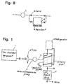
- Figure 1 shows a basic structure of the gas reclaiming equipment.
- the gas reclaiming equipment is used for reclaiming the gas from gas insulated equipment 1.
- the gas reclaiming equipment consists of a filter 2, a vacuum/compression pump 3, a gas liquefaction system 6, an SF 6 liquid tank 7, a refrigerator 11, and a cooling pipe 12.
- the gas-insulated equipment 1, the filter 2, the vacuum/compression pump 3, the gas liquefaction system 6, and the SF 6 liquid tank 7 are connected to each other through a pipe 13.
- a valve 14 for controlling the flow rate from the gas liquefaction system 6 or the SF 6 liquid tank 7 is provided.
- the filter 2 adsorbs decomposed gas of SF 6 , which occurs due to an arc.
- the filter also absorbs particulate foreign substances.
- an adsorbent is used for the purpose of removing moisture or decomposed gas.
- Zeolites with a pore size of approximately 5 ⁇ or 10 ⁇ (5 ⁇ 10 -10 m or 10 ⁇ 10 -10 m) are commonly used, since the decomposed gas molecules are larger than a molecule of H 2 O. Even, Zeolites with pore size of 9 ⁇ (9 ⁇ 10 -10 m) can be used. That is, the size depends on what kind of gas is being reclaimed.
- the SF 6 gas is sent into the gas liquefaction system 6 from the gas insulated equipment 1 through the vacuum/compression pump 3. Additionally, a refrigerant, like chlorofluorocarbon, is sent through the cooling pipe 12 from the refrigerator 11. The SF 6 gas is liquefied in the gas liquefaction system 6 and then the reclaimed SF 6 liquid is stored in liquid tank 7.
- the reactivity of HF is the highest and HF is chemisorbed. Its adsorption energy is about 100kcal/mol (419 J/mol). It is believed that the rest of the gasses are absorbed by physisorption. The adsorption energy in physisorption is approximately 1-4 kcal/about mol (4,19-16,75 J/about mol).
- physisorption is weaker in terms of adsorption. So, it is believed that gas molecules de-sorb from the adsorbent under the influence of molecular movement in a reduced pressure state. In addition, even if the molecule with weak adsorption is adsorbed by physisorption, when a molecule with strong adsorption arrives, the molecular with strong adsorption adsorbs such that the molecule with the strong adsorption replaces the molecule with weak adsorption.
- gases such as SOF 2 , SO 2 F 2 , CO 2 , SF 6 , CF 4 , N 2 , and O 2 de-sorb from the adsorbent. Therefore, gases such as SOF 2 , SO 2 F 2 , CO 2 , SF 6 , CF 4 , N 2 , and O 2 may exhaust from the gas insulated equipment 1, and may go into the reclaiming equipment. If so, the filter 2 catches the decomposed gas and any foreign substances, and prevents invasion of the decomposed gas and foreign substances into the gas liquefaction system 6.
- the quantity of exhaustd SF 6 gas needs to be reduced further.
- mixed gas having nitrogen gas as a main component and a little SF 6 gas
- nitrogen gas does not liquefy simultaneously. Nitrogen still exists as a gas. Therefore, it is possible to liquefy only SF 6 gas in a mixed gas and to separate SF 6 gas from nitrogen gas.
- the pressurization liquefaction of SF 6 gas is easy at room temperature, such as 20 degrees C.
- the concentrated SF 6 gas is liquefied in the gas liquefaction system 6, but the main composition gas, such as nitrogen gas, of the mixed gas continues to accumulate in the gas gradually liquefaction system 6. Therefore, before exceeding the design pressure of the gas liquefaction system 6, this main composition gas needs to be extracted from the gas liquefaction system 6.
- the main composition gas may contain some SF 6 gas, and thus the main composition gas cannot be emitted into the atmosphere. Therefore, in order to prevent the SF 6 gas from remaining in the main composition gas, the reclaiming ratio of SF 6 gas is preferably improved. Moreover, in considering reclaiming the mixed gas, the gas pressure in the gas-insulated equipment is high early in the reclaiming stage. Therefore, the gas automatically flows into the reclaiming equipment side by only opening a valve. As a result, adjusting the flow rate is easier.
- the reclaiming work under reduced pressure becomes necessary.
- the reclaiming work depends on the capability of the vacuum/pressurization pump.
- the processing quantity per unit time is reduced under reduced pressure. Therefore, it becomes difficult to secure a sufficient flow rate and the reclaiming efficiency is lowered.
- decomposed gas de-sorbs from the adsorbent in the gas insulated equipment beforehand. Therefore, the decomposed gas will be exhausted into the reclaiming equipment side.
- Decomposed gas If the decomposed gas enters the reclaiming equipment, the life of the reclaiming equipment is adversely affected. Decomposed gas causes, for example, chemical degradation of the pipes in the reclaiming equipment and degradation of the material of the adsorbent.
- an adsorbent having various Zeolites for example Zeolites with 5 ⁇ or 10 ⁇ (5 ⁇ 10 -10 m or 10 ⁇ 10 -10 m) pores, are usually enclosed.
- the adsorbent includes Zeolites with approximately 10 ⁇ (10 ⁇ 10 -10 m) pores which adsorbs SF 6 gas for reclaiming. Therefore, if there is a high quantity of the adsorbent, when reclaiming in a reduced pressure condition, the SF 6 gas will de-sorb from the gas insulated equipment side gradually for a long period of time. Therefore, there is a problem in that the reclaiming of SF 6 gas takes a long time.
- the adsorbent material has Zeolites with a size of 5 ⁇ (5 ⁇ 10 -10 m), it is difficult to adsorb a decomposed gas larger than 5 ⁇ (5 ⁇ 10 -10 m) in size, and the rate of absorption may decrease.
- the present invention has been made in view of the above-mentioned circumstances and is intended to solve the above-mentioned problems.
- the object of the present invention is to provide a gas reclaiming equipment having a simple and inexpensive structure, and capable of reclaiming SF 6 gas with high efficiency.
- the present invention provides a gas reclaiming equipment including the features of independent claims 1 or 4 and a method comprising the features of claim 13.
- Advantageous empodiments of the invention are defined in the subclaims.
- Fig. 2 is a diagram showing gas reclaiming equipment according to a first embodiment of the present invention.
- a gas separation equipment 5 is provided between a gas insulated equipment 1 and a gas liquefaction system 6.
- the gas separation equipment 5 separates nitrogen gas from mixed gas, and concentrates the SF 6 gas. Thereafter, concentrated SF 6 gas which contains small amount of nitrogen gas is sent into the gas liquefaction system 6.
- the gas separation equipment 5 includes pressure swing adsorption using an adsorbent with selective adsorption. Moreover, a buffer tank 4, which stores the mixed gas temporarily, is provided between the gas separation equipment 5 and the gas insulated equipment 1. The buffer tank 4 is operated on the condition that the inside of the buffer tank is pressurized at all times.
- the buffer tank 4 and the gas liquefaction system 6 are connected by a reflux-line 19.
- the reflux-line 19 refluxes the gas in a gas-phase from the gas liquefaction system 6 to the buffer tank 4.
- the gas-phase contains a small quantity of SF 6 gas which is equivalents to the vapor pressure of SF 6 .
- the gas separation equipment 5 is connected to a storage tank 8 for exhaust gas.
- the storage tank 8 accumulates the nitrogen gas separated through the gas separation equipment 5.
- the adsorbent 18 having approximately 10 ⁇ (10 ⁇ 10 -10 m) Zeolites for adsorbing SF 6 gas is enclosed in the storage tank 8 for the exhaust gas.
- a filter 2 having an adsorbent 2a of the chemisorption type to absorb decomposed gas is interposed between the gas insulated equipment and a pump 3.
- the adsorbent 2a has a metal hydrate, such as Ca(OH) 2 .
- a valve 14 controls the flow.
- a control unit 9 controls the entire gas reclaiming equipment.
- Zeolites shown in Fig. 3, used as the adsorbent, are enclosed in the gas separation equipment 5.
- Zeolites are a generic name for crystalline aluminosilicates of alkali.
- the general formula of Zeolites is shown by MeO ⁇ Al 2 O 3 ⁇ mSiO 2 ⁇ nH 2 O.
- Zeolites have uniform pores on their surface.
- a molecule smaller than the pore can pass along a narrow pipe of Zeolites, the molecule can be adsorbed inside, as illustrated in Fig. 10.
- the pores in the Zeolite act like small holes while the molecules of SF 6 and nitrogen gas act like small balls.
- the balls of the same size as the pores get stuck in the pores. This illustrates the outstanding selective adsorption, or molecular sieve effect.
- SF 6 gas and nitrogen gas differ from each other in molecular size.
- the size of the SF 6 molecule varies from DS5.49 - DL6.06, and the size of the nitrogen molecule has from DS3.1 - DL4.2.
- the unit of size is ⁇ or 10 -10 m.
- DS shows the shorter parameter of the molecule.
- DL shows the longer parameter of the molecule.
- Molecular size is described with DS and DL because of its non-spherical shape.
- SF 6 gas is not adsorbed. This is because SF 6 gas is larger than the pore in the Zeolite surface. Nitrogen gas is adsorbed alternatively, and separation of SF 6 gas is provided.
- Zeolites have a metal cation in the crystal structure.
- the metal cation attracts a polar group by static electricity, or a neutral molecule electrically by polarization.
- the metal cation is widely applicable based on the above mentioned reason.
- the gas separation equipment 5 separates the mixed gas with Zeolites by the selective adsorption mentioned above using the pressure swing adsorption method.
- the basic principle of the pressure swing adsorption method is that the adsorption quantity of the adsorbent is proportional to the gas pressure.
- Fig. 4 is a graph showing the relationship between the adsorption quantity and pressure.
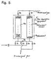
- Fig. 5 is a detailed diagram showing a main part of the gas separation equipment 5. That is, the gas separation equipment 5 has two adsorbent vessels 15a and 15b. An adsorbent 16 with 5 ⁇ Zeolites is contained in the two adsorbent vessels 15a and 15b.
- valves B1, B2, B3, B4, B5, B6 and B7 The fundamental run pattern of valves B1, B2, B3, B4, B5, B6 and B7 will now be explained.
- Valves B1 and B4 are open, and the other valves are closed.
- valve B4 is combined with the vacuum/compression pump 3 on the condition that valve B4 is open, and reduced pressure processing is carried out.
- the mixed gas in the gas insulated equipment flows to a down-stream side with the vacuum/compression pump 3, through the buffer tank 4.
- the mixed gas flows into the adsorbent vessel 15a in the gas separation equipment 5.
- the adsorbent vessel 15b is controlled by the vacuum/compression pump 3 under reduced pressure. It is in the early regeneration state and emits the adsorbed nitrogen gas. In the adsorbent vessel 15a, the adsorbent adsorbs only nitrogen gas by the molecular sieve effect. On the one hand, SF 6 gas flows along the upper part, along the flow route, raising its concentration. Finally, gas with high SF 6 gas concentration accumulates on the upper part of the adsorbent vessel 15a.
- valve B6 While valve B6 is closed, the flow route of mixed gas is changed into the adsorbent vessel 15b side by opening valve B3. Thus, SF 6 gas will be separated and concentrated in the adsorbent vessel 15b.
- reduced pressure processing in the adsorbent vessel 15a side is carried out, and the nitrogen gas de-sorbs. While the nitrogen gas is exhausted by opening valve B2, the adsorbent 16 will be in the initial state before the adsorbent starts adsorbing.
- mixed gas is separated into SF 6 gas and nitrogen gas.
- SF 6 concentrated gas is then sent into the gas liquefaction system 6.
- the initial performance deteriorates gradually due to the strong bonding of moisture and decomposed gas with the adsorbent 16.
- a designated purity control needs to be carried out.
- the gas flowed into the reclaiming equipment should be controlled.
- the liquefaction pressure will be set to about 4 MPa at room temperature. Therefore, the existing liquefaction equipment can be used and the risk of liquefaction under high-pressure is also decreased remarkably. Moreover, even though the liquefaction may be performed by using cooling, the increase in size of the equipment is avoidable.
- the liquefaction pressure can be reduced up to about 1.3 MPa.
- mixed gas can be accumulated in the buffer tank 4 temporarily. Therefore, the operation after the gas separation equipment 5 can be stopped, and sufficient flow rate and amount of mixture gas which put into the gas separation equipment 5 can be secured by gas accumulation into buffer tank 4. That is, the appropriate gas flow rate under the reduced pressure condition can be realized, and high reclaiming efficiency can be maintained.
- the decomposed gas contained in the mixed gas does not desorb. Furthermore, in the first embodiment, the adsorbent 2a of the chemisorption type in the filter 2 catches the decomposed gas with certainty. Therefore, the decomposed gas is mixed neither into the gas separation equipment 5 nor the gas liquefaction system 6.
- the performance degradation related to chemical factors and physical factors does not occur.
- the lifetime of the equipment can be prolonged.
- the adsorbent 18 in the storage tank 8 for exhaust gas adsorbs only SF 6 gas.
- the same effects can be obtained using the column containing the adsorbent 18 instead of the storage tank 8.
- Fig. 6 shows the change of SF 6 gas concentration of a mixed gas with 5% SF 6 gas at a pressure of 0.2MPa when using an adsorbent comprising 10 ⁇ (10 ⁇ 10 -10 m) Zeolites.
- Fig. 6 shows that the adsorbent also adsorbs a very small quantity of SF 6 gas with certainty.
- SF 6 gas adsorption with an adsorbent 18 having the 10 ⁇ (10 ⁇ 10 -10 m) Zeolites become saturated. Therefore, after the predetermined quantity processing of SF 6 gas, while SF 6 gas is reclaimed under the reduced pressure, the adsorbent 18 needs to be restored into its initial condition.
- the vacuum/compression pump 3 sends the mixed gas having nitrogen gas, which is the main ingredient, and SF 6 gas into the buffer tank 4, through the piping 13.
- the adsorption power of the adsorbent is in inverse proportion to temperature. That is, if temperature is lowered, SF 6 gas adsorbed to the Zeolites increases. On the one hand, SF 6 gas remaining in the gas phase decreases.
- the temperature is raised, the adsorption power will decline, and if the temperature is lowered, the adsorption power increases. That is, when the reproducing of adsorbent work is required in a short time, it is better that the temperature is at 80-100 degrees C.
- SF 6 gas can be adsorbed by supplying exhaust gas into an adsorbent vessel filled with an adsorbent 18 of 10 ⁇ (10 ⁇ 10 -10 m) Zeolites.
- adsorbent 18 10 ⁇ (10 ⁇ 10 -10 m) Zeolites.
- the reduced pressure processing is carried out at a gas exit side
- SF 6 gas will disperse to the adsorbent in a non-adsorbed portion. Therefore, it is better to perform the reduced pressure processing and to reproduce the adsorbent from the gas entrance side of the column (not shown) provided in the storage tank 8 for exhaust gas. Therefore, it is not necessary to supply a trap at the storage tank 8. That is, the same effect as the mentioned effect can be attained by flowing the exhaust gas to the adsorbent vessel, filled with the adsorbent 18 having 10 ⁇ (10 ⁇ 10 -10 m) Zeolites.
- the gas separation equipment 5 separates mixed gas into SF 6 gas and nitrogen gas. In this separation operation, preventing SF 6 gas mixing into nitrogen gas as much as possible is desirable. For this reason, when sending SF 6 gas reclaimed in the gas separation equipment 5 to the pump 3, SF 6 gas is also reclaimed by supplying the nitrogen gas together.
- nitrogen gas can be returned to the buffer tank 4 from the gas liquefaction system 6 through the reflux-line 19.
- the reclaiming efficiency of SF 6 gas improves sharply by passing this gas again through the gas separation equipment 5 and the gas liquefaction system 6, even though SF 6 gas remains mixed in the nitrogen gas. Therefore, in the reclaiming SF 6 gas, the amount of exhaust of SF 6 gas to the atmosphere can be ignored.
- a second embodiment is shown in Fig. 7 and Fig. 8.
- the second embodiment encloses an adsorbent 16 with 5 ⁇ and 10 ⁇ (5 ⁇ 10 -10 m or 10 ⁇ 10 -10 m) Zeolites in the buffer tank 4.
- Fig. 7 two buffer tanks 4a and 4b are provided. Furthermore, the adsorbent 16 is enclosed only within the buffer tank 4b. In this embodiment, the pressure of the mixed gas is reduced by controlling the valve 14, and mixed gas is reclaimed.
- the buffer tanks 4a and 4b, having the adsorbent 16, serve so that the mixed gas may be stored.
- the adsorbent 16 enclosed in the buffer tank 4b can reliably catch the decomposed gas which pass through the filter 2.
- the decomposed gas does not mix in the gas separation equipment 5 or the gas liquefaction system 6. Therefore, it is possible to prevent the chemical degradation and physical degradation and to prolong the lifetime of the equipment.
- the mixed gas can be stored in the buffer tanks 4a and 4b. Further, the mixed gas can only be passed under a designated pressurization state through the buffer tanks 4a and 4b to an atmospheric pressure.
- the mixed gas can be reclaimed quickly, and shortening of reclaiming work hours can be attained.
- an adsorbent 16 with 5 ⁇ and 10 ⁇ (5 ⁇ 10 -10 m or 10 ⁇ 10 -10 m) Zeolites is used, the quantity of the adsorption of SF 6 gas can be suppressed. Furthermore, it is possible to adsorb a molecule larger than 5 ⁇ (5 ⁇ 10 -10 m) quickly from the decomposed gas.
- a film for the gas separation equipment can be used. That is, the thing adapting the difference of the dissolution to a molecular size, a film material for example, can be considered.
- a film material made from a macromolecule can be used as an example.
- the gas reclaiming equipment can have plural gas separation units.
- This embodiment is illustrated in Fig. 9.
- the mixed gas is led to a 1st gas separation unit 21, and the 1st step gas separation unit 21 reclaims concentrated SF 6 gas.
- gas exhausted from the gas reclaiming equipment is led to a 2nd gas separation unit 23.
- the 2nd step of the gas separation unit 23 again concentrates SF 6 gas contained in a very small quantity.
- SF 6 gas with high purity and the reduction of the liquefaction pressure of SF 6 gas can be attained by performing plural gas separation processes.
- another embodiment relates to the gas insulated equipment side for making gas reclaiming easy.
- an adsorbent with 5 ⁇ and 10 ⁇ (5 ⁇ 10 -10 m or 10 ⁇ 10 -10 m) Zeolites is enclosed as a decomposed gas removal material and a desiccant in the gas insulated equipment 1.
- the embodiment is characterized by enclosing an adsorbent mixture with 5 ⁇ and 10 ⁇ (5 ⁇ 10 -10 m or 10 ⁇ 10 -10 m) Zeolites.
- the former becomes more than 80wt% and the latter becomes less than 20wt%.
- the quantity of SO 2 F 2 generated is small compared with SOF 2 generated, and it is known that it is ordinarily 1/10 or less.
- the adsorbent has two types, approximately 5 ⁇ (5 ⁇ 10 -10 m) size and 10 ⁇ (10 ⁇ 10 -10 m) size of pores in the gas-insulated equipment 1, according to the above-mentioned ratio.
- the quantity of SF 6 gas adsorption in the gas insulated equipment 1 can be minimized, while maintaining the adsorption performance of the decomposed gas. That is, SF 6 gas does not escape from the gas-insulated equipment 1 for a long period of time, when reduced pressure reclaiming is performed. Consequently, reclaiming working hours can be shortened and reclaiming efficiency improved.
- the reclaiming performance of SF 6 gas can be improved by setting the reflux-line and returning the gas in the gas phase in the gas liquefaction system to the mixed gas introduction section.
- SF 6 gas and other insulated gases are efficiently separable with a unique adsorption action of the adsorbent.
- Shortening of reclaiming working hours can be attained by this separation, raising SF 6 gas concentration and raising the reclaiming efficiency under reduced pressure. Furthermore, according to the present invention, longevity of the life of the equipment can be enabled by removing decomposed gas exhausted from the gas insulated equipment. Furthermore, the optimization of the combination and ratio in the adsorbent in the gas insulated equipment can be attained, and outstanding reclaiming efficiency can be demonstrated.
Landscapes
- Chemical & Material Sciences (AREA)
- Engineering & Computer Science (AREA)
- Analytical Chemistry (AREA)
- General Chemical & Material Sciences (AREA)
- Oil, Petroleum & Natural Gas (AREA)
- Chemical Kinetics & Catalysis (AREA)
- Health & Medical Sciences (AREA)
- Biomedical Technology (AREA)
- Environmental & Geological Engineering (AREA)
- Gas-Insulated Switchgears (AREA)
- Separation Of Gases By Adsorption (AREA)
- Driving Mechanisms And Operating Circuits Of Arc-Extinguishing High-Tension Switches (AREA)
Abstract
Description
- The present invention relates to gas reclaiming equipment used for gas insulated equipment filled with an insulating gas, and more particularly to gas reclaiming equipment adapted for gas-insulated equipment filled with environmentally problematic gasses such as SF6/nitrogen insulating gas mixtures.
- Generally, a substation has a circuit breaker and a disconnector to perform a system change and a maintenance check. In particular, large-sized equipment from among the above mentioned equipment using gas insulated equipment filled with SF6 gas is especially adopted.
- Generally, SF6 gas is highly desirable because of its insulation performance and arc interruption performance. Moreover, since SF6 gas is a chemically stable and harmless gas, it has been widely adopted as an insulation medium in the above-mentioned equipment. However, SF6 gas contributes to the greenhouse effect and has a long decomposition life.
- Because of environmental protection concerns over a long period of time, the exhaust of SF6 gas is regulated. Therefore, when performing periodic inspection and parts exchange, the SF6 gas should be reclaimed so that it does not leak to the outside from the gas insulated equipment.
- When reclaiming and storing the SF6 gas, a large-size tank for storing the SF6 gas is necessary as the volume of the SF6 gas gets large. However, it is advantageous to change the gas into a high-pressure state and to reduce the volume of the SF6 gas. This, however, may generate safety problems.
- Accordingly, it has been proposed to use gas reclaiming equipment that converts the SF6 gas to SF6 liquid by pressurization and liquefaction of SF6. By using such equipment, the tank for reclaiming can be greatly reduced. Furthermore, the safety can be improved.
- Figure 1 shows a basic structure of the gas reclaiming equipment. The gas reclaiming equipment is used for reclaiming the gas from gas insulated equipment 1. The gas reclaiming equipment consists of a
filter 2, a vacuum/compression pump 3, agas liquefaction system 6, an SF6liquid tank 7, arefrigerator 11, and acooling pipe 12. - The gas-insulated equipment 1, the
filter 2, the vacuum/compression pump 3, thegas liquefaction system 6, and the SF6liquid tank 7 are connected to each other through apipe 13. Avalve 14 for controlling the flow rate from thegas liquefaction system 6 or the SF6liquid tank 7 is provided. In addition, thefilter 2 adsorbs decomposed gas of SF6, which occurs due to an arc. The filter also absorbs particulate foreign substances. - SF6 gas with high-purity and high- dryness is required for the gas insulated equipment 1. Therefore, an adsorbent is used for the purpose of removing moisture or decomposed gas. As the adsorbent. Zeolites with a pore size of approximately 5Å or 10Å (5 · 10-10 m or 10 · 10-10 m) are commonly used, since the decomposed gas molecules are larger than a molecule of H2O. Even, Zeolites with pore size of 9Å (9 · 10-10 m) can be used. That is, the size depends on what kind of gas is being reclaimed.
- In a conventional gas reclaiming equipment, the SF6 gas is sent into the
gas liquefaction system 6 from the gas insulated equipment 1 through the vacuum/compression pump 3. Additionally, a refrigerant, like chlorofluorocarbon, is sent through thecooling pipe 12 from therefrigerator 11. The SF6 gas is liquefied in thegas liquefaction system 6 and then the reclaimed SF6 liquid is stored inliquid tank 7. - If moisture, and various decomposition gases (HF, H2O, SO2 and SOF2, SO2F2), and a related gas molecule (CF4), are put in order in terms of the largest to smallest adsorption power, the order could be shown below:
- HF, H2O, SO2 and SOF2, SO2F2, CO2, SF6, CF4, N2, O2
-
- In the above-mentioned list, the reactivity of HF is the highest and HF is chemisorbed. Its adsorption energy is about 100kcal/mol (419 J/mol). It is believed that the rest of the gasses are absorbed by physisorption. The adsorption energy in physisorption is approximately 1-4 kcal/about mol (4,19-16,75 J/about mol).
- Compared with chemisorption, physisorption is weaker in terms of adsorption. So, it is believed that gas molecules de-sorb from the adsorbent under the influence of molecular movement in a reduced pressure state. In addition, even if the molecule with weak adsorption is adsorbed by physisorption, when a molecule with strong adsorption arrives, the molecular with strong adsorption adsorbs such that the molecule with the strong adsorption replaces the molecule with weak adsorption.
- Among these gases, it is hard to de-sorb moisture under reduced pressure. However, under a reduced pressure state for reclaiming SF6 gas, gases such as SOF2, SO2F2, CO2, SF6, CF4, N2, and O2 de-sorb from the adsorbent. Therefore, gases such as SOF2, SO2F2, CO2, SF6, CF4, N2, and O2 may exhaust from the gas insulated equipment 1, and may go into the reclaiming equipment. If so, the
filter 2 catches the decomposed gas and any foreign substances, and prevents invasion of the decomposed gas and foreign substances into thegas liquefaction system 6. - For sake of the earth's environment, the quantity of exhaustd SF6 gas needs to be reduced further. For that purpose, it is desirable to reduce the quantity of SF6 gas used.
- The use of mixed gas, having nitrogen gas as a main component and a little SF6 gas, is considered to be effective in the curtailment of SF6 gas. However, the properties of SF6 gas and nitrogen gas differ remarkably. That is, under the conditions in which SF6 gas liquefies, nitrogen gas does not liquefy simultaneously. Nitrogen still exists as a gas. Therefore, it is possible to liquefy only SF6 gas in a mixed gas and to separate SF6 gas from nitrogen gas.
- The characteristic values of mixture ratio and liquefaction pressure are shown in Table 1.
Mixture ratio Liquefaction pressure 100 vol % SF6 gas 2 MPa 50 vol % SF6 gas 4 MPa 10 vol % SF6 gas More than 20 MPa - If the purity of SF6 gas is high, the pressurization liquefaction of SF6 gas is easy at room temperature, such as 20 degrees C.
- However, in order to liquefy SF6 gas in a mixed gas, high pressure is needed.
- As shown in Table 1, since in the case of 10vol% SF6 gas a pressure of 20 MPa or more is needed at room temperature, the liquefaction of SF6 is very difficult. Moreover, large-sized refrigeration equipment needs to be used and the liquefaction pressure needs to be lowered. Consequently, the enlargement of equipment has become a problem in reclaiming and recycling mixed gas.
- Gas reclaiming equipment is disclosed in Japanese Patent Disclosure (Kokai) No.2000-135412. However, there are the following problems with the conventional technology of reclaiming mixed gases containing SF6 gas. That is, when a mixed gas is incorporated into the
gas liquefaction system 6 and thegas liquefaction system 6 liquefies SF6 gas continuously, the following problem occurs. - The concentrated SF6 gas is liquefied in the
gas liquefaction system 6, but the main composition gas, such as nitrogen gas, of the mixed gas continues to accumulate in the gas graduallyliquefaction system 6. Therefore, before exceeding the design pressure of thegas liquefaction system 6, this main composition gas needs to be extracted from thegas liquefaction system 6. - However, the main composition gas may contain some SF6 gas, and thus the main composition gas cannot be emitted into the atmosphere. Therefore, in order to prevent the SF6 gas from remaining in the main composition gas, the reclaiming ratio of SF6 gas is preferably improved. Moreover, in considering reclaiming the mixed gas, the gas pressure in the gas-insulated equipment is high early in the reclaiming stage. Therefore, the gas automatically flows into the reclaiming equipment side by only opening a valve. As a result, adjusting the flow rate is easier.
- However, in the case when the reclaiming work has been performed, the reclaiming work under reduced pressure becomes necessary. The reclaiming work depends on the capability of the vacuum/pressurization pump. The processing quantity per unit time is reduced under reduced pressure. Therefore, it becomes difficult to secure a sufficient flow rate and the reclaiming efficiency is lowered.
- Furthermore, when gas is forcibly extracted with the vacuum/pressurization pump, decomposed gas de-sorbs from the adsorbent in the gas insulated equipment beforehand. Therefore, the decomposed gas will be exhausted into the reclaiming equipment side.
- If the decomposed gas enters the reclaiming equipment, the life of the reclaiming equipment is adversely affected. Decomposed gas causes, for example, chemical degradation of the pipes in the reclaiming equipment and degradation of the material of the adsorbent.
- Therefore, it is desirable that the decomposed gas exhausted from the gas insulated equipment be captured with certainty. Moreover, as mentioned above, in the gas insulated equipment, an adsorbent having various Zeolites, for example Zeolites with 5Å or 10Å (5 · 10-10 m or 10 · 10-10 m) pores, are usually enclosed.
- At this time, the adsorbent includes Zeolites with approximately 10Å (10 · 10-10 m) pores which adsorbs SF6 gas for reclaiming. Therefore, if there is a high quantity of the adsorbent, when reclaiming in a reduced pressure condition, the SF6 gas will de-sorb from the gas insulated equipment side gradually for a long period of time. Therefore, there is a problem in that the reclaiming of SF6 gas takes a long time. On the other hand, if the adsorbent material has Zeolites with a size of 5Å (5 · 10-10 m), it is difficult to adsorb a decomposed gas larger than 5Å (5 · 10-10 m) in size, and the rate of absorption may decrease.
- Therefore, optimization of the combination of Zeolites in the adsorbent in the gas-insulated equipment is desired.
- The present invention has been made in view of the above-mentioned circumstances and is intended to solve the above-mentioned problems. In particular, the object of the present invention is to provide a gas reclaiming equipment having a simple and inexpensive structure, and capable of reclaiming SF6 gas with high efficiency.
- The present invention provides a gas reclaiming equipment including the features of
independent claims 1 or 4 and a method comprising the features ofclaim 13. Advantageous empodiments of the invention are defined in the subclaims. - The accompanying drawings, which are incorporated in and constitute a part of this specification, illustrate several preferred embodiments of the present invention and, together with the description, serve to explain the principles of the present invention.
- Fig. 1 is a diagram showing a basic structure of conventional pure SF6 gas reclaiming equipment.
- Fig. 2 is a diagram showing gas reclaiming equipment according to a first embodiment of the present invention.
- Fig. 3 is a diagram showing the gas separation principle according to the first embodiment of the present invention.
- Fig. 4 is a graph showing the relationship between the amount of adsorption and the pressure of Zeolites.
- Fig. 5 is a detailed diagram showing the gas reclaiming equipment according to the first embodiment of the present invention.
- Fig. 6 is a graph showing the adsorption characteristics of a Zeolite.
- Fig. 7 is a diagram showing the gas reclaiming equipment according to a second embodiment of the present invention.
- Fig. 8 is a diagram showing the gas reclaiming equipment according to another embodiment of the present invention.
- Fig. 9 is a diagram showing an embodiment of the invention with plural gas separation units.
- Fig. 10 is a diagram further explaining the gas separation principle.
-
- Preferred embodiments of gas reclaiming equipment of the present invention are now specifically described in more detail with reference to the accompanying drawings. Wherever possible, the same reference numbers are used throughout the drawings to refer to the same or like parts.
- Fig. 2 is a diagram showing gas reclaiming equipment according to a first embodiment of the present invention. A
gas separation equipment 5 is provided between a gas insulated equipment 1 and agas liquefaction system 6. Thegas separation equipment 5 separates nitrogen gas from mixed gas, and concentrates the SF6 gas. Thereafter, concentrated SF6 gas which contains small amount of nitrogen gas is sent into thegas liquefaction system 6. - The
gas separation equipment 5 includes pressure swing adsorption using an adsorbent with selective adsorption. Moreover, abuffer tank 4, which stores the mixed gas temporarily, is provided between thegas separation equipment 5 and the gas insulated equipment 1. Thebuffer tank 4 is operated on the condition that the inside of the buffer tank is pressurized at all times. - The
buffer tank 4 and thegas liquefaction system 6 are connected by a reflux-line 19. The reflux-line 19 refluxes the gas in a gas-phase from thegas liquefaction system 6 to thebuffer tank 4. The gas-phase contains a small quantity of SF6 gas which is equivalents to the vapor pressure of SF6. Furthermore, thegas separation equipment 5 is connected to astorage tank 8 for exhaust gas. Thestorage tank 8 accumulates the nitrogen gas separated through thegas separation equipment 5. - The adsorbent 18 having approximately 10Å (10 · 10-10 m) Zeolites for adsorbing SF6 gas is enclosed in the
storage tank 8 for the exhaust gas. Afilter 2 having an adsorbent 2a of the chemisorption type to absorb decomposed gas is interposed between the gas insulated equipment and apump 3. The adsorbent 2a has a metal hydrate, such as Ca(OH)2. - The above components are connected with the
pipe 13. Avalve 14 controls the flow. Acontrol unit 9 controls the entire gas reclaiming equipment. - Operation of the first embodiment will now be described. First, the separation principle of gas in the
gas separation equipment 5 is explained by reference to Fig. 2, Fig. 3, and Fig. 4 and Fig. 10. - The Zeolites shown in Fig. 3, used as the adsorbent, are enclosed in the
gas separation equipment 5. Zeolites are a generic name for crystalline aluminosilicates of alkali. The general formula of Zeolites is shown by MeO· Al2O3· mSiO2· nH2O. Moreover, Zeolites have uniform pores on their surface. - Since only a molecule smaller than the pore can pass along a narrow pipe of Zeolites, the molecule can be adsorbed inside, as illustrated in Fig. 10. The pores in the Zeolite act like small holes while the molecules of SF6 and nitrogen gas act like small balls. Theballs" of the same size as the pores get stuck in the pores. This illustrates the outstanding selective adsorption, or molecular sieve effect.

- On the one hand, SF6 gas and nitrogen gas differ from each other in molecular size. The size of the SF6 molecule varies from DS5.49 - DL6.06, and the size of the nitrogen molecule has from DS3.1 - DL4.2. The unit of size is Å or 10-10m. DS shows the shorter parameter of the molecule. DL shows the longer parameter of the molecule. Molecular size is described with DS and DL because of its non-spherical shape.
- When using Zeolite with a pore-diameter of 5 Å(5 · 10-10 m), SF6 gas is not adsorbed. This is because SF6 gas is larger than the pore in the Zeolite surface. Nitrogen gas is adsorbed alternatively, and separation of SF6 gas is provided.
- Zeolites have a metal cation in the crystal structure. The metal cation attracts a polar group by static electricity, or a neutral molecule electrically by polarization. Thus, it is believed that the metal cation is widely applicable based on the above mentioned reason.
- The
gas separation equipment 5 separates the mixed gas with Zeolites by the selective adsorption mentioned above using the pressure swing adsorption method. The basic principle of the pressure swing adsorption method is that the adsorption quantity of the adsorbent is proportional to the gas pressure. Fig. 4 is a graph showing the relationship between the adsorption quantity and pressure. - Fig. 5 is a detailed diagram showing a main part of the
gas separation equipment 5. That is, thegas separation equipment 5 has twoadsorbent vessels adsorbent vessels - The fundamental run pattern of valves B1, B2, B3, B4, B5, B6 and B7 will now be explained. Valves B1 and B4 are open, and the other valves are closed. Moreover, valve B4 is combined with the vacuum/
compression pump 3 on the condition that valve B4 is open, and reduced pressure processing is carried out. - First, separation of SF6 gas will be explained. The mixed gas in the gas insulated equipment flows to a down-stream side with the vacuum/
compression pump 3, through thebuffer tank 4. The mixed gas flows into theadsorbent vessel 15a in thegas separation equipment 5. - At this time, the
adsorbent vessel 15b is controlled by the vacuum/compression pump 3 under reduced pressure. It is in the early regeneration state and emits the adsorbed nitrogen gas. In theadsorbent vessel 15a, the adsorbent adsorbs only nitrogen gas by the molecular sieve effect. On the one hand, SF6 gas flows along the upper part, along the flow route, raising its concentration. Finally, gas with high SF6 gas concentration accumulates on the upper part of theadsorbent vessel 15a. - When the pressure in the
adsorbent vessel 15a gets to a predetermined pressure, inflow of mixed gas is stopped, by closing the valve B1, and SF6 gas concentrated by opening valve B6 is reclaimed. In addition, for better efficiency and stability, values within the limits at 0.2-0.5MPa are usually used. - Subsequently, while valve B6 is closed, the flow route of mixed gas is changed into the
adsorbent vessel 15b side by opening valve B3. Thus, SF6 gas will be separated and concentrated in theadsorbent vessel 15b. First, reduced pressure processing in theadsorbent vessel 15a side is carried out, and the nitrogen gas de-sorbs. While the nitrogen gas is exhausted by opening valve B2, the adsorbent 16 will be in the initial state before the adsorbent starts adsorbing. - By repeating the above-mentioned operation, mixed gas is separated into SF6 gas and nitrogen gas. SF6 concentrated gas is then sent into the
gas liquefaction system 6. - As mentioned above, only nitrogen gas smaller than the pore diameter of the adsorbent 16 can be adsorbed during the adsorption process using high pressure. If the pressure is reduced in the adsorption process, the nitrogen gas currently adsorbed to the adsorbent 16 will de-sorb, and, finally nitrogen gas will be exhausted. Furthermore, the adsorbent 16 will be in the initial state simultaneously through this operation. Then, again, when the gas pressure increases, the same quantity of nitrogen gas exhausted can be absorbed. Thus, a repeating operation of absorption and regeneration makes semi-permanent separation of the mixed gas possible.
- However, as mentioned above, the initial performance deteriorates gradually due to the strong bonding of moisture and decomposed gas with the adsorbent 16. In such a situation, in order to prevent mixing of the decomposed gas, a designated purity control needs to be carried out. The gas flowed into the reclaiming equipment should be controlled.
- As mentioned above, if the initial 10 vol % SF6 gas is condensed upto 50 vol % of the mixed gas, the liquefaction pressure will be set to about 4 MPa at room temperature. Therefore, the existing liquefaction equipment can be used and the risk of liquefaction under high-pressure is also decreased remarkably. Moreover, even though the liquefaction may be performed by using cooling, the increase in size of the equipment is avoidable.
- For example, at 20 degrees C, the liquefaction pressure can be reduced up to about 1.3 MPa. Moreover, even if pressure of gas insulaterd equipment 1 is reduced in the reclaiming process and the flow rate of mixed gas decreases, mixed gas can be accumulated in the
buffer tank 4 temporarily. Therefore, the operation after thegas separation equipment 5 can be stopped, and sufficient flow rate and amount of mixture gas which put into thegas separation equipment 5 can be secured by gas accumulation intobuffer tank 4. That is, the appropriate gas flow rate under the reduced pressure condition can be realized, and high reclaiming efficiency can be maintained. - In addition, when the quantity of gas runs short in the
buffer tank 4, then stopping the reclaiming operation and closing valves is carried out, and the remained reclaiming process can be carried out at the following gas reclaiming operation for another gas insulated equipment. Reduced pressure processing is unnecessary in thebuffer tank 4 for the above reason. - On the other hand, the decomposed gas contained in the mixed gas does not desorb. Furthermore, in the first embodiment, the adsorbent 2a of the chemisorption type in the
filter 2 catches the decomposed gas with certainty. Therefore, the decomposed gas is mixed neither into thegas separation equipment 5 nor thegas liquefaction system 6. - Therefore, the performance degradation related to chemical factors and physical factors does not occur. Thus, the lifetime of the equipment can be prolonged. Moreover, though a very small quantity of SF6 gas remains in the nitrogen gas separated with the
gas separation equipment 5, the adsorbent 18 in thestorage tank 8 for exhaust gas adsorbs only SF6 gas. The same effects can be obtained using the column containing the adsorbent 18 instead of thestorage tank 8. - Fig. 6 shows the change of SF6 gas concentration of a mixed gas with 5% SF6 gas at a pressure of 0.2MPa when using an adsorbent comprising 10Å (10 · 10-10 m) Zeolites. Fig. 6 shows that the adsorbent also adsorbs a very small quantity of SF6 gas with certainty. In addition, SF6 gas adsorption with an adsorbent 18 having the 10Å (10 · 10-10 m) Zeolites become saturated. Therefore, after the predetermined quantity processing of SF6 gas, while SF6 gas is reclaimed under the reduced pressure, the adsorbent 18 needs to be restored into its initial condition.
- In this case, the vacuum/
compression pump 3 sends the mixed gas having nitrogen gas, which is the main ingredient, and SF6 gas into thebuffer tank 4, through thepiping 13. Moreover, experiments show that the adsorption power of the adsorbent is in inverse proportion to temperature. That is, if temperature is lowered, SF6 gas adsorbed to the Zeolites increases. On the one hand, SF6 gas remaining in the gas phase decreases. - In other words, if the temperature is raised, the adsorption power will decline, and if the temperature is lowered, the adsorption power increases. That is, when the reproducing of adsorbent work is required in a short time, it is better that the temperature is at 80-100 degrees C.
- Since the separation reclaiming is carried out, almost all exhaust of SF6 gas to the atmosphere can be reduced to the appropriate exhaust level. Thus, the exhaust level shows outstanding environmental harmony.
- Moreover, as shown in Fig. 6, according to the experiment, it is ascertained that SF6 gas can be adsorbed by supplying exhaust gas into an adsorbent vessel filled with an adsorbent 18 of 10Å (10 · 10-10 m) Zeolites. In this case, if the reduced pressure processing is carried out at a gas exit side, SF6 gas will disperse to the adsorbent in a non-adsorbed portion. Therefore, it is better to perform the reduced pressure processing and to reproduce the adsorbent from the gas entrance side of the column (not shown) provided in the
storage tank 8 for exhaust gas. Therefore, it is not necessary to supply a trap at thestorage tank 8. That is, the same effect as the mentioned effect can be attained by flowing the exhaust gas to the adsorbent vessel, filled with the adsorbent 18 having 10Å (10 · 10-10 m) Zeolites. - As mentioned above, in the first embodiment, the
gas separation equipment 5 separates mixed gas into SF6 gas and nitrogen gas. In this separation operation, preventing SF6 gas mixing into nitrogen gas as much as possible is desirable. For this reason, when sending SF6 gas reclaimed in thegas separation equipment 5 to thepump 3, SF6 gas is also reclaimed by supplying the nitrogen gas together. - In this case, if the reclaiming operation is continued, SF6 gas and the nitrogen gas continue to accumulate in the
gas liquefaction system 6. In other words, although SF6 gas is liquefied by thegas liquefaction system 6, the nitrogen gas continues to accumulate gradually in the gas state. Therefore, the pressure in thegas liquefaction system 6 may exceed the design pressure. - To prevent this problem, in the first embodiment, nitrogen gas can be returned to the
buffer tank 4 from thegas liquefaction system 6 through the reflux-line 19. Thereby, an improvement in safety is obtained. Further, the reclaiming efficiency of SF6 gas improves sharply by passing this gas again through thegas separation equipment 5 and thegas liquefaction system 6, even though SF6 gas remains mixed in the nitrogen gas. Therefore, in the reclaiming SF6 gas, the amount of exhaust of SF6 gas to the atmosphere can be ignored. - In addition, the same effect as mentioned above can be achieved by keeping nitrogen gas in another container temporarily and returning it to the
gas separation equipment 5, instead of returning the nitrogen gas through the reflux-line 19 automatically. - A second embodiment is shown in Fig. 7 and Fig. 8. The second embodiment encloses an adsorbent 16 with 5Å and 10Å (5 · 10-10 m or 10 · 10-10 m) Zeolites in the
buffer tank 4. - In Fig. 7, two
buffer tanks 4a and 4b are provided. Furthermore, the adsorbent 16 is enclosed only within thebuffer tank 4b. In this embodiment, the pressure of the mixed gas is reduced by controlling thevalve 14, and mixed gas is reclaimed. Thebuffer tanks 4a and 4b, having the adsorbent 16, serve so that the mixed gas may be stored. - According to this embodiment, the adsorbent 16 enclosed in the
buffer tank 4b can reliably catch the decomposed gas which pass through thefilter 2. - Furthermore, the decomposed gas does not mix in the
gas separation equipment 5 or thegas liquefaction system 6. Therefore, it is possible to prevent the chemical degradation and physical degradation and to prolong the lifetime of the equipment. - Only when the mixed gas is reclaimed under the reduced pressure, the mixed gas can be stored in the
buffer tanks 4a and 4b. Further, the mixed gas can only be passed under a designated pressurization state through thebuffer tanks 4a and 4b to an atmospheric pressure. - Therefore, at the beginning of the reclaiming work, with the high gas pressure of the gas-insulated equipment 1, the mixed gas can be reclaimed quickly, and shortening of reclaiming work hours can be attained. Moreover, since an adsorbent 16 with 5Å and 10Å (5 · 10-10 m or 10 · 10-10 m) Zeolites is used, the quantity of the adsorption of SF6 gas can be suppressed. Furthermore, it is possible to adsorb a molecule larger than 5Å (5 · 10-10 m) quickly from the decomposed gas.
- In addition, it is good not to perform the reduced pressure processing in the
buffer tanks 4a and 4b, but to perform an operation-stop in the state where a pressure has slightly been applied. That is, it can prevent the decomposed gas from de-sorbing from the adsorbent by applying a pressure within about 0.1-0.2 MPa, for a while. Furthermore, a film for the gas separation equipment, as another embodiment, can be used. That is, the thing adapting the difference of the dissolution to a molecular size, a film material for example, can be considered. A film material made from a macromolecule can be used as an example. - Even, as a further embodiment, the gas reclaiming equipment can have plural gas separation units. This embodiment is illustrated in Fig. 9. For example, in the first place, the mixed gas is led to a 1st
gas separation unit 21, and the 1st stepgas separation unit 21 reclaims concentrated SF6 gas. Then, gas exhausted from the gas reclaiming equipment is led to a 2ndgas separation unit 23. The 2nd step of thegas separation unit 23 again concentrates SF6 gas contained in a very small quantity. - According to this embodiment, SF6 gas with high purity and the reduction of the liquefaction pressure of SF6 gas can be attained by performing plural gas separation processes.
- Moreover, another embodiment relates to the gas insulated equipment side for making gas reclaiming easy. In this embodiment, an adsorbent with 5Å and 10Å (5 · 10-10 m or 10 · 10-10 m) Zeolites is enclosed as a decomposed gas removal material and a desiccant in the gas insulated equipment 1. As the object for the dryness in the gas insulated equipment 1, and the adsorbent for decomposed gas removal, the embodiment is characterized by enclosing an adsorbent mixture with 5Å and 10Å (5 · 10-10 m or 10 · 10-10 m) Zeolites.
- As for the ratio of the adsorbent with 5Å and 10Å (5 · 10-10 m or 10 · 10-10 m) Zeolites, it is desirable that the former becomes more than 80wt% and the latter becomes less than 20wt%.
- The quantity of SO2F2 generated is small compared with SOF2 generated, and it is known that it is ordinarily 1/10 or less. In this embodiment, the adsorbent has two types, approximately 5Å (5 · 10-10 m) size and 10Å (10 · 10-10 m) size of pores in the gas-insulated equipment 1, according to the above-mentioned ratio.
- The quantity of SF6 gas adsorption in the gas insulated equipment 1 can be minimized, while maintaining the adsorption performance of the decomposed gas. That is, SF6 gas does not escape from the gas-insulated equipment 1 for a long period of time, when reduced pressure reclaiming is performed. Consequently, reclaiming working hours can be shortened and reclaiming efficiency improved.
- According to the present invention, the reclaiming performance of SF6 gas can be improved by setting the reflux-line and returning the gas in the gas phase in the gas liquefaction system to the mixed gas introduction section. Moreover, according to the present invention, SF6 gas and other insulated gases are efficiently separable with a unique adsorption action of the adsorbent.
- Shortening of reclaiming working hours can be attained by this separation, raising SF6 gas concentration and raising the reclaiming efficiency under reduced pressure. Furthermore, according to the present invention, longevity of the life of the equipment can be enabled by removing decomposed gas exhausted from the gas insulated equipment. Furthermore, the optimization of the combination and ratio in the adsorbent in the gas insulated equipment can be attained, and outstanding reclaiming efficiency can be demonstrated.
- Japanese priority Application No. PH 11-282045, filed on October 1, 1999, including the specification, drawings, claims and abstract, is hereby incorporated by reference.
Claims (21)
- A gas reclaiming equipment, which is applied to a gas insulated equipment (1) filled with mixed gas including an insulated gas which has SF6 gas as an ingredient, comprising:a filter (2) for removing a decomposed gas and a foreign particulate substance from said mixed gas which is sent from said gas insulated equipment (1);a gas liquefaction system (6) for reclaiming said mixed gas, wherein said gas liquefaction system (6) liquefies said SF6 gas of said mixed gas by pressurizing said mixed gas;a pump (3) for sending said mixed gas from said gas insulated equipment (1) to said gas liquefaction system (6);a storage tank (7) for accumulating a SF6 liquid obtained with said gas liquefaction system (6); anda line (19) for returning a gas in the gas phase in said gas liquefaction system (6) to an upstream side of said gas liquefaction system (6).
- The gas reclaiming equipment according to claim 1, wherein said filter (2) has an adsorbent of a chemisorption type which absorbs said decomposed gas.
- The gas reclaiming equipment according to claim 1 or 2, wherein said gas insulated equipment has an adsorbent having Zeolites with approximately 5Å (5 · 10-10 m) size and 10Å (10 · 10-10 m) size, and having a ratio of said Zeolites wherein the 5Å (5 · 10-10 m) size is more than 80wt% and said Zeolites with 10Å (10 · 10-10 m) size is less than 20wt%.
- A gas reclaiming equipment, which is applied to a gas insulated equipment (1) filled with mixed gas including an insulated gas like SF6 gas, comprising:a first filter (2) for removing a decomposed gas and a foreign particulate substance from said mixed gas which is sent from said gas insulated equipment (1);a gas liquefaction system (6) for reclaiming said mixed gas, wherein said gas liquefaction system (6) liquefies said SF6 gas of said mixed by pressurizing said mixed gas;a pump (3) for sending said mixed gas from said gas insulated equipment to said gas liquefaction system (6);a first storage tank (7) for accumulating a SF6 liquid obtained by said gas liquefaction system (6);a gas separation equipment (5) for separating said SF6 gas from said mixed gas, and sending said SF6 gas into said gas liquefaction system (6), said gas separation equipment (5) being provided between said gas insulated equipment and said gas liquefaction system (6); anda buffer tank (4) for storing said mixed gas, said buffer tank (4) being provided between said gas insulated equipment and said gas separation equipment (5).
- The gas reclaiming equipment according to claim 4, wherein said buffer tank (4) has an adsorbent comprising Zeolites with 5Å size and 10Å size.
- The gas reclaiming equipment according to claim 4 or 5, wherein said buffer tank (4) stores said mixed gas when said mixed gas is reclaimed under reduced pressure.
- The gas reclaiming equipment according to any of claims 4 to 6, wherein said gas separation equipment (5) includes pressure swing adsorption including an adsorbent with selective adsorption.
- The gas reclaiming equipment according to any of claims 4 to 7, wherein said gas separation equipment (5) has a second filter (2) with a permeable membrane.
- The gas reclaiming equipment according to any of claims 4 to 8, wherein said gas separation equipment (5) has plural separating units (21, 23) to separate said SF6 gas from said mixed gas.
- The gas reclaiming equipment according to any of claims 4 to 9, further comprising:a second storage tank (8) storing a specified gas separated by said gas separation equipment (5), said second storage tank (8) including an adsorbent (18) to adsorb said SF6 gas.
- The gas reclaiming equipment according to any of claims 4 to 10, wherein said filter (2) has an adsorbent to adsorb said decomposed gas.
- The gas reclaiming equipment according to any of claims 4 to 11, wherein said gas separation equipment (5) includes an adsorbent having Zeolites with approximately 5Å size and 10Å size, and wherein a ratio of said Zeolites with 5Å size is more than 80wt% and said Zeolites with 10Å size is less than 20wt%.
- A method of reclaiming insulating gas from a mixed gas of a gas insulated equipment comprising:flowing the mixed gas though a filter (2) to remove decomposed gas and foreign particulate substances;flowing the mixed gas to a gas liquefaction system;liquefying the insulating gas; andreturning gas in the gas phase from the gas liquefaction system to an upstream side of the gas liquefaction system.
- The method of claim 13, further comprising chemisorbing decomposed gas in said filter (2).
- The method of claim 13 or 14, further comprising flowing said mixed gas through a gas separation unit.
- The method of claim 15, wherein said gas separation unit includes an adsorbent having Zeolites with approximately 5Å size and 10Å size, and wherein the portion of said Zeolites with 5Å size is more than 80wt% and said Zeolites with 10Å size is less than 20wt%.
- The method of any of claims 13 to 16, further comprising flowing mixed gas from said gas separating equipment to a storage tank (7).
- The method of claim 17, wherein said storage tank (7) includes an adsorbent to adsorb decomposed gas.
- The method of claim 17, wherein said storage tank (7) includes an adsorbent to adsorb SF6 gas.
- The method of any of claims 13 to 19, further comprising flowing the mixed gas through a buffer tank (4).
- The method of claim 20, wherein said buffer tank (4) includes an adsorbent having Zeolites with approximately 5Å size and 10Å size, and wherein a ratio of said Zeolites with 5Å size is more than 80wt% and said Zeolites with 10Å size is less than 20wt%.
Applications Claiming Priority (2)
| Application Number | Priority Date | Filing Date | Title |
|---|---|---|---|
| JP28204599 | 1999-10-01 | ||
| JP28204599A JP4357046B2 (en) | 1999-10-01 | 1999-10-01 | Gas recovery device |
Publications (3)
| Publication Number | Publication Date |
|---|---|
| EP1091182A2 true EP1091182A2 (en) | 2001-04-11 |
| EP1091182A3 EP1091182A3 (en) | 2002-01-16 |
| EP1091182B1 EP1091182B1 (en) | 2004-11-17 |
Family
ID=17647459
Family Applications (1)
| Application Number | Title | Priority Date | Filing Date |
|---|---|---|---|
| EP00121476A Expired - Lifetime EP1091182B1 (en) | 1999-10-01 | 2000-09-29 | Gas reclaiming equipment |
Country Status (4)
| Country | Link |
|---|---|
| US (1) | US6966934B1 (en) |
| EP (1) | EP1091182B1 (en) |
| JP (1) | JP4357046B2 (en) |
| DE (1) | DE60015900T2 (en) |
Cited By (10)
| Publication number | Priority date | Publication date | Assignee | Title |
|---|---|---|---|---|
| WO2014173776A1 (en) * | 2013-04-22 | 2014-10-30 | Abb Technology Ag | Process for providing a contamination-reducing component to an electrical apparatus |
| WO2014187940A1 (en) * | 2013-05-23 | 2014-11-27 | Abb Technology Ag | Electrical apparatus comprising a contamination-reducing component |
| WO2015071303A1 (en) * | 2013-11-12 | 2015-05-21 | Abb Technology Ag | Water and contamination absorber for c02 insulated electrical apparatus for the generation, transmission, distribution and/or usage of electrical energy |
| EP2904617B1 (en) | 2012-10-05 | 2016-11-30 | ABB Schweiz AG | Apparatus containing a dielectric insulation gas comprising an organofluorine compound |
| WO2016193272A1 (en) * | 2015-06-02 | 2016-12-08 | Firma Dilo Armaturen Und Anlagen Gmbh | Service device for use during maintenance of electrical switchgears insulated using a multi-component insulating gas |
| WO2017012775A1 (en) * | 2015-07-20 | 2017-01-26 | Siemens Aktiengesellschaft | High or medium voltage arrangement with insulation chamber and an absorer with selective membrane |
| EP3069421B1 (en) | 2013-11-12 | 2017-09-20 | ABB Schweiz AG | Water and contamination adsorber for co2 insulated electrical apparatus for the generation, transmission, distribution and/or usage of electrical energy |
| EP3146531B1 (en) | 2014-05-20 | 2018-03-21 | ABB Schweiz AG | Electrical apparatus for the generation, transmission, distribution and/or usage of electrical energy and method for recovering a substance from an insulation medium of such an apparatus |
| WO2019047349A1 (en) * | 2017-09-08 | 2019-03-14 | 河南平高电气股份有限公司 | Gas recovery and inflation device and sulfur hexafluoride gas recovery and inflation device |
| EP3834917A1 (en) * | 2019-12-13 | 2021-06-16 | WIKA Alexander Wiegand SE & Co. KG | Service system for gas areas |
Families Citing this family (13)
| Publication number | Priority date | Publication date | Assignee | Title |
|---|---|---|---|---|
| US9064372B2 (en) | 2002-02-15 | 2015-06-23 | Wms Gaming Inc. | Wagering game with simulated mechanical reels having an overlying image display |
| JP4596531B2 (en) * | 2005-03-11 | 2010-12-08 | 財団法人電力中央研究所 | Gas insulated power equipment and abnormality detection method thereof |
| JP5020059B2 (en) * | 2007-12-28 | 2012-09-05 | 三菱電機株式会社 | Gas insulated switchgear |
| KR101155996B1 (en) | 2010-09-30 | 2012-06-18 | 한국에너지기술연구원 | Recovery device of the insulation gas and system control method thereof |
| DE102015206744A1 (en) * | 2015-04-15 | 2016-11-03 | Rwe Deutschland Ag | Method for drying a gas space and arrangement comprising a protective gas-filled gas space |
| DE102015213597A1 (en) * | 2015-07-20 | 2017-01-26 | Siemens Aktiengesellschaft | High or medium voltage arrangement with insulating space and absorbent |
| EP3174071B1 (en) * | 2015-11-30 | 2018-11-14 | General Electric Technology GmbH | Method and installation for filling a gas-insulated switchgear comprising a mixture of (cf3)2cfcn and co2 |
| DE102016215598A1 (en) * | 2016-08-19 | 2018-02-22 | Siemens Aktiengesellschaft | Electric power transmission device and life cycle management |
| CN106352658B (en) * | 2016-10-27 | 2022-06-07 | 刘克军 | Oxidation tail gas treatment device for cyclohexanone device and application thereof |
| CN107726043B (en) * | 2017-09-08 | 2020-04-07 | 国家电网公司 | Mixed gas transformation method of 110kV sulfur hexafluoride gas insulation current transformer |
| CN108101006B (en) * | 2017-12-20 | 2020-01-24 | 国网河北省电力有限公司电力科学研究院 | SF (sulfur hexafluoride)6And N2Device and method for rapidly recovering and treating mixed gas |
| CN108261885A (en) * | 2017-12-29 | 2018-07-10 | 浙江环耀环境建设有限公司 | A kind of organic waste gas treatment system and solvent recovery process |
| CN110833730A (en) * | 2019-11-15 | 2020-02-25 | 昆山开信精工机械股份有限公司 | Nitrogen mixed material separation device and separation method for liquefiable gas |
Citations (7)
| Publication number | Priority date | Publication date | Assignee | Title |
|---|---|---|---|---|
| DE2336331A1 (en) * | 1973-07-12 | 1975-01-30 | Rudolf Dittmar | Purifying sulphur hexafluoride for electrical insulation - by liquefaction in external circuit to separate gaseous impurities |
| JPS6326497A (en) * | 1986-07-17 | 1988-02-04 | Kachi Tekkosho:Kk | Gas replacement recovery device |
| US5720797A (en) * | 1996-12-18 | 1998-02-24 | Alliedsignal Inc. | Process for recovering sulfur hexafluoride |
| EP0853970A2 (en) * | 1997-01-16 | 1998-07-22 | L'air Liquide, Societe Anonyme Pour L'etude Et L'exploitation Des Procedes Georges Claude | An improved process and system for separation and recovery of perfluorocompound gases |
| EP0885841A1 (en) * | 1997-06-20 | 1998-12-23 | Hitachi Engineering & Services Co., Ltd. | System and method for collecting and refining SF6 gas |
| EP0976439A1 (en) * | 1998-07-27 | 2000-02-02 | Mitsubishi Denki Kabushiki Kaisha | Method and apparatus for recovering condensable gas from mixed gas |
| WO2000010688A1 (en) * | 1998-08-20 | 2000-03-02 | Solvay Fluor Und Derivate Gmbh | Separation of gases containing sf¿6? |
Family Cites Families (26)
| Publication number | Priority date | Publication date | Assignee | Title |
|---|---|---|---|---|
| US3210952A (en) * | 1961-12-11 | 1965-10-12 | Westinghouse Electric Corp | Reclamation device for gas-type circuit interrupters |
| DE1212945B (en) * | 1964-07-07 | 1966-03-24 | Kali Chemie Ag | Process for the removal of sulfuryl fluoride from gas mixtures containing sulfur hexafluoride |
| US3675392A (en) * | 1970-01-30 | 1972-07-11 | Ite Imperial Corp | Adsorption-desorption method for purifying sf{11 |
| JPS545393B2 (en) * | 1973-08-08 | 1979-03-16 | ||
| US3992159A (en) * | 1975-06-23 | 1976-11-16 | Bell Telephone Laboratories, Incorporated | Process for purification by cryogenic sublimation |
| AU520049B2 (en) * | 1976-08-16 | 1982-01-14 | University Of Sydney, The | Cryogenic pumping system |
| AU4587479A (en) * | 1978-04-07 | 1979-10-11 | Commonwealth Industrial Gases Limited, The | Pressure-swing preferential adsorption of condensible vapour from gas stream |
| JPH0127240Y2 (en) * | 1980-03-03 | 1989-08-15 | ||
| JPS59179414U (en) * | 1983-05-17 | 1984-11-30 | 株式会社東芝 | SF6 liquefaction recovery equipment for gas insulated equipment |
| JPS6018775A (en) * | 1983-07-11 | 1985-01-30 | Mitsubishi Electric Corp | Internal abnormality detector for gas insulated electric equipment |
| JPS61167309A (en) * | 1985-01-18 | 1986-07-29 | 株式会社東芝 | Gas substituting apparatus and method |
| JPH0755807B2 (en) * | 1987-11-04 | 1995-06-14 | 三井東圧化学株式会社 | Method for producing nitrogen trifluoride |
| WO1990015662A1 (en) * | 1989-06-15 | 1990-12-27 | Du Pont Canada Inc. | Perfluorodioxole membranes |
| JPH04293512A (en) * | 1991-03-25 | 1992-10-19 | Kobe Steel Ltd | Gas purification device |
| US5240471A (en) * | 1991-07-02 | 1993-08-31 | L'air Liquide | Multistage cascade-sweep process for membrane gas separation |
| US5252219A (en) * | 1992-12-18 | 1993-10-12 | Permea, Inc. | Compressed permeate sweep membrane separation process |
| US5378263A (en) * | 1992-12-21 | 1995-01-03 | Praxair Technology, Inc. | High purity membrane nitrogen |
| US5482539A (en) * | 1993-09-22 | 1996-01-09 | Enerfex, Inc. | Multiple stage semi-permeable membrane process and apparatus for gas separation |
| US5417742A (en) * | 1993-12-03 | 1995-05-23 | The Boc Group, Inc. | Removal of perfluorocarbons from gas streams |
| US5455016A (en) * | 1994-08-31 | 1995-10-03 | Air Products And Chemicals, Inc. | Membrane-assisted process to produce ammonia |
| US5502969A (en) * | 1995-02-16 | 1996-04-02 | Praxair Technology, Inc. | Cryogenic rectification system for fluorine compound recovery |
| FR2730790B1 (en) * | 1995-02-17 | 1997-05-23 | Air Liquide | METHOD FOR INTRODUCING A FILLING GAS INTO AN ENCLOSURE AND INSTALLATION FOR IMPLEMENTING IT |
| JPH08309146A (en) * | 1995-05-22 | 1996-11-26 | Boc Group Inc:The | Separation method for perfluorocarbon from gas current |
| US5785741A (en) * | 1995-07-17 | 1998-07-28 | L'air Liquide, Societe Anonyme Pour L'etude Et L'exploitation Des Procedes Georges, Claude | Process and system for separation and recovery of perfluorocompound gases |
| JP3237514B2 (en) * | 1996-04-23 | 2001-12-10 | 三菱電機株式会社 | Sulfur hexafluoride gas recovery and regeneration device and mobile recovery and regeneration device |
| US5730779A (en) * | 1996-10-31 | 1998-03-24 | Air Products And Chemicals, Inc. | Fluorochemical recovery and recycle using membranes |
-
1999
- 1999-10-01 JP JP28204599A patent/JP4357046B2/en not_active Expired - Fee Related
-
2000
- 2000-09-29 DE DE60015900T patent/DE60015900T2/en not_active Expired - Lifetime
- 2000-09-29 US US09/672,775 patent/US6966934B1/en not_active Expired - Fee Related
- 2000-09-29 EP EP00121476A patent/EP1091182B1/en not_active Expired - Lifetime
Patent Citations (7)
| Publication number | Priority date | Publication date | Assignee | Title |
|---|---|---|---|---|
| DE2336331A1 (en) * | 1973-07-12 | 1975-01-30 | Rudolf Dittmar | Purifying sulphur hexafluoride for electrical insulation - by liquefaction in external circuit to separate gaseous impurities |
| JPS6326497A (en) * | 1986-07-17 | 1988-02-04 | Kachi Tekkosho:Kk | Gas replacement recovery device |
| US5720797A (en) * | 1996-12-18 | 1998-02-24 | Alliedsignal Inc. | Process for recovering sulfur hexafluoride |
| EP0853970A2 (en) * | 1997-01-16 | 1998-07-22 | L'air Liquide, Societe Anonyme Pour L'etude Et L'exploitation Des Procedes Georges Claude | An improved process and system for separation and recovery of perfluorocompound gases |
| EP0885841A1 (en) * | 1997-06-20 | 1998-12-23 | Hitachi Engineering & Services Co., Ltd. | System and method for collecting and refining SF6 gas |
| EP0976439A1 (en) * | 1998-07-27 | 2000-02-02 | Mitsubishi Denki Kabushiki Kaisha | Method and apparatus for recovering condensable gas from mixed gas |
| WO2000010688A1 (en) * | 1998-08-20 | 2000-03-02 | Solvay Fluor Und Derivate Gmbh | Separation of gases containing sf¿6? |
Non-Patent Citations (2)
| Title |
|---|
| PATENT ABSTRACTS OF JAPAN vol. 012, no. 229 (M-714), 29 June 1988 (1988-06-29) & JP 63 026497 A (KACHI TEKKOSHO:KK), 4 February 1988 (1988-02-04) * |
| PATENT ABSTRACTS OF JAPAN vol. 1998, no. 03, 27 February 1998 (1998-02-27) -& JP 09 285719 A (MITSUBISHI ELECTRIC CORP), 4 November 1997 (1997-11-04) -& DATABASE WPI Derwent Publications Ltd., London, GB; AN 1998-027131 XP002183539 * |
Cited By (14)
| Publication number | Priority date | Publication date | Assignee | Title |
|---|---|---|---|---|
| EP2904617B1 (en) | 2012-10-05 | 2016-11-30 | ABB Schweiz AG | Apparatus containing a dielectric insulation gas comprising an organofluorine compound |
| WO2014173776A1 (en) * | 2013-04-22 | 2014-10-30 | Abb Technology Ag | Process for providing a contamination-reducing component to an electrical apparatus |
| WO2014187940A1 (en) * | 2013-05-23 | 2014-11-27 | Abb Technology Ag | Electrical apparatus comprising a contamination-reducing component |
| US10522981B2 (en) | 2013-11-12 | 2019-12-31 | Abb Schweiz Ag | Water and contamination absorber for C02 insulated electrical apparatus for the generation, transmission, distribution and/or usage of electrical energy |
| WO2015071303A1 (en) * | 2013-11-12 | 2015-05-21 | Abb Technology Ag | Water and contamination absorber for c02 insulated electrical apparatus for the generation, transmission, distribution and/or usage of electrical energy |
| CN105874665A (en) * | 2013-11-12 | 2016-08-17 | Abb 技术有限公司 | Water and contamination absorber for c02 insulated electrical apparatus for the generation, transmission, distribution and/or usage of electrical energy |
| EP3069421B1 (en) | 2013-11-12 | 2017-09-20 | ABB Schweiz AG | Water and contamination adsorber for co2 insulated electrical apparatus for the generation, transmission, distribution and/or usage of electrical energy |
| CN105874665B (en) * | 2013-11-12 | 2019-06-21 | Abb瑞士股份有限公司 | For generate, transmit, distribute and/or using electric energy CO2The water and pollutant absorbent of insulation electric installation |
| EP3146531B1 (en) | 2014-05-20 | 2018-03-21 | ABB Schweiz AG | Electrical apparatus for the generation, transmission, distribution and/or usage of electrical energy and method for recovering a substance from an insulation medium of such an apparatus |
| WO2016193272A1 (en) * | 2015-06-02 | 2016-12-08 | Firma Dilo Armaturen Und Anlagen Gmbh | Service device for use during maintenance of electrical switchgears insulated using a multi-component insulating gas |
| US10914424B2 (en) | 2015-06-02 | 2021-02-09 | Dilo Armaturen Und Anlagen Gmbh | Service device and method for using a multi-component insulating gas during maintenance of electrical switchgear systems |
| WO2017012775A1 (en) * | 2015-07-20 | 2017-01-26 | Siemens Aktiengesellschaft | High or medium voltage arrangement with insulation chamber and an absorer with selective membrane |
| WO2019047349A1 (en) * | 2017-09-08 | 2019-03-14 | 河南平高电气股份有限公司 | Gas recovery and inflation device and sulfur hexafluoride gas recovery and inflation device |
| EP3834917A1 (en) * | 2019-12-13 | 2021-06-16 | WIKA Alexander Wiegand SE & Co. KG | Service system for gas areas |
Also Published As
| Publication number | Publication date |
|---|---|
| DE60015900D1 (en) | 2004-12-23 |
| JP2001110284A (en) | 2001-04-20 |
| JP4357046B2 (en) | 2009-11-04 |
| DE60015900T2 (en) | 2005-11-03 |
| EP1091182B1 (en) | 2004-11-17 |
| US6966934B1 (en) | 2005-11-22 |
| EP1091182A3 (en) | 2002-01-16 |
Similar Documents
| Publication | Publication Date | Title |
|---|---|---|
| EP1091182B1 (en) | Gas reclaiming equipment | |
| US6004377A (en) | System for collecting and refining SF6 gas and method therefor | |
| US8795411B2 (en) | Method for recovering high-value components from waste gas streams | |
| US7824472B2 (en) | Method and apparatus for pressure swing adsorption | |
| US20020023539A1 (en) | Method for storing natural gas by adsorption and adsorbing agent for use therein | |
| KR100790696B1 (en) | Processing and recovery device and method of hydrocarbon gas | |
| EP1759760A2 (en) | Adsorbent for the adsorption and storage of natural gas and use thereof | |
| US10619114B2 (en) | Pretreatment equipment for hydrocarbon gas to be liquefied and shipping base equipment | |
| JP2003103134A (en) | Gaseous sf 6 sampling device and method for the same | |
| KR20190052018A (en) | A method for purifying hydrogen or helium and a method for purifying hydrogen or helium | |
| JPH0947635A (en) | Treatment and recovery device for gaseous hydrogen contained in waste gas and its process | |
| JP2000262806A (en) | Adsorbent regeneration method | |
| KR20010114209A (en) | Method for treating dilute gaseous hydrogen carbide contained in waste gas and device for performing the method | |
| JP4405039B2 (en) | Gas recovery device and gas recovery method | |
| US20050274125A1 (en) | Methods of dissolving ozone in a cryogen | |
| JP2005199223A (en) | Recovery method and recovery device of gasoline vapor | |
| JP2001143580A (en) | Apparatus for separating and recovering gas | |
| JP2000274938A (en) | Gas recovery system | |
| JP5693448B2 (en) | Gaseous hydrocarbon recovery apparatus and method | |
| JP2001283692A (en) | Separation-recovery apparatus for sf6 gas | |
| JP2000135412A (en) | Gas recovering device and gas recovery | |
| JP2587334B2 (en) | Method of separating CO gas not containing CH4 | |
| JP2002114504A (en) | Device and method for recovering sf6 gas | |
| JP2006242141A (en) | Gas compressor and gas pressure raising method | |
| JP6837375B2 (en) | Hydrogen gas purification equipment and operation method of hydrogen gas purification equipment |
Legal Events
| Date | Code | Title | Description |
|---|---|---|---|
| PUAI | Public reference made under article 153(3) epc to a published international application that has entered the european phase |
Free format text: ORIGINAL CODE: 0009012 |
|
| 17P | Request for examination filed |
Effective date: 20000929 |
|
| AK | Designated contracting states |
Kind code of ref document: A2 Designated state(s): AT BE CH CY DE DK ES FI FR GB GR IE IT LI LU MC NL PT SE Kind code of ref document: A2 Designated state(s): CH DE LI |
|
| AX | Request for extension of the european patent |
Free format text: AL;LT;LV;MK;RO;SI |
|
| PUAL | Search report despatched |
Free format text: ORIGINAL CODE: 0009013 |
|
| RIC1 | Information provided on ipc code assigned before grant |
Free format text: 7F 25J 3/06 A, 7F 25J 3/08 B, 7B 01D 53/04 B |
|
| AK | Designated contracting states |
Kind code of ref document: A3 Designated state(s): AT BE CH CY DE DK ES FI FR GB GR IE IT LI LU MC NL PT SE |
|
| AX | Request for extension of the european patent |
Free format text: AL;LT;LV;MK;RO;SI |
|
| AKX | Designation fees paid |
Free format text: CH DE LI |
|
| 17Q | First examination report despatched |
Effective date: 20030821 |
|
| GRAP | Despatch of communication of intention to grant a patent |
Free format text: ORIGINAL CODE: EPIDOSNIGR1 |
|
| GRAS | Grant fee paid |
Free format text: ORIGINAL CODE: EPIDOSNIGR3 |
|
| GRAA | (expected) grant |
Free format text: ORIGINAL CODE: 0009210 |
|
| AK | Designated contracting states |
Kind code of ref document: B1 Designated state(s): CH DE LI |
|
| REG | Reference to a national code |
Ref country code: CH Ref legal event code: EP |
|
| REG | Reference to a national code |
Ref country code: IE Ref legal event code: FG4D |
|
| REF | Corresponds to: |
Ref document number: 60015900 Country of ref document: DE Date of ref document: 20041223 Kind code of ref document: P |
|
| REG | Reference to a national code |
Ref country code: CH Ref legal event code: NV Representative=s name: E. BLUM & CO. PATENTANWAELTE |
|
| PLBE | No opposition filed within time limit |
Free format text: ORIGINAL CODE: 0009261 |
|
| STAA | Information on the status of an ep patent application or granted ep patent |
Free format text: STATUS: NO OPPOSITION FILED WITHIN TIME LIMIT |
|
| 26N | No opposition filed |
Effective date: 20050818 |
|
| REG | Reference to a national code |
Ref country code: CH Ref legal event code: PFA Owner name: KABUSHIKI KAISHA TOSHIBA Free format text: KABUSHIKI KAISHA TOSHIBA#72 HORIKAWA-CHO, SAIWAI-KU#KAWASAKI-SHI, KANAGAWA-KEN (JP) -TRANSFER TO- KABUSHIKI KAISHA TOSHIBA#72 HORIKAWA-CHO, SAIWAI-KU#KAWASAKI-SHI, KANAGAWA-KEN (JP) |
|
| PGFP | Annual fee paid to national office [announced via postgrant information from national office to epo] |
Ref country code: CH Payment date: 20140915 Year of fee payment: 15 Ref country code: DE Payment date: 20140923 Year of fee payment: 15 |
|
| REG | Reference to a national code |
Ref country code: DE Ref legal event code: R119 Ref document number: 60015900 Country of ref document: DE |
|
| REG | Reference to a national code |
Ref country code: CH Ref legal event code: PL |
|
| PG25 | Lapsed in a contracting state [announced via postgrant information from national office to epo] |
Ref country code: CH Free format text: LAPSE BECAUSE OF NON-PAYMENT OF DUE FEES Effective date: 20150930 Ref country code: DE Free format text: LAPSE BECAUSE OF NON-PAYMENT OF DUE FEES Effective date: 20160401 Ref country code: LI Free format text: LAPSE BECAUSE OF NON-PAYMENT OF DUE FEES Effective date: 20150930 |