EP1090667B1 - Soupape de vidange pour un séparateur d'eau de filtre à carburant - Google Patents
Soupape de vidange pour un séparateur d'eau de filtre à carburant Download PDFInfo
- Publication number
- EP1090667B1 EP1090667B1 EP20000308733 EP00308733A EP1090667B1 EP 1090667 B1 EP1090667 B1 EP 1090667B1 EP 20000308733 EP20000308733 EP 20000308733 EP 00308733 A EP00308733 A EP 00308733A EP 1090667 B1 EP1090667 B1 EP 1090667B1
- Authority
- EP
- European Patent Office
- Prior art keywords
- port
- drain
- drain valve
- piston
- passage
- Prior art date
- Legal status (The legal status is an assumption and is not a legal conclusion. Google has not performed a legal analysis and makes no representation as to the accuracy of the status listed.)
- Expired - Lifetime
Links
- XLYOFNOQVPJJNP-UHFFFAOYSA-N water Substances O XLYOFNOQVPJJNP-UHFFFAOYSA-N 0.000 title claims description 69
- 239000000446 fuel Substances 0.000 title claims description 58
- 238000011144 upstream manufacturing Methods 0.000 claims description 55
- 238000002485 combustion reaction Methods 0.000 claims description 7
- 230000013011 mating Effects 0.000 claims description 6
- 239000007921 spray Substances 0.000 claims description 5
- 230000000903 blocking effect Effects 0.000 claims description 4
- 238000000034 method Methods 0.000 claims 3
- 238000007789 sealing Methods 0.000 description 8
- 239000002283 diesel fuel Substances 0.000 description 7
- 239000013618 particulate matter Substances 0.000 description 4
- 230000000694 effects Effects 0.000 description 2
- 238000002347 injection Methods 0.000 description 2
- 239000007924 injection Substances 0.000 description 2
- 239000004215 Carbon black (E152) Substances 0.000 description 1
- 230000007797 corrosion Effects 0.000 description 1
- 238000005260 corrosion Methods 0.000 description 1
- 238000001914 filtration Methods 0.000 description 1
- 238000010438 heat treatment Methods 0.000 description 1
- 229930195733 hydrocarbon Natural products 0.000 description 1
- 150000002430 hydrocarbons Chemical class 0.000 description 1
- 239000012535 impurity Substances 0.000 description 1
- JEIPFZHSYJVQDO-UHFFFAOYSA-N iron(III) oxide Inorganic materials O=[Fe]O[Fe]=O JEIPFZHSYJVQDO-UHFFFAOYSA-N 0.000 description 1
- 239000007788 liquid Substances 0.000 description 1
- 230000014759 maintenance of location Effects 0.000 description 1
- 230000007257 malfunction Effects 0.000 description 1
- 230000000717 retained effect Effects 0.000 description 1
Images


Classifications
-
- B—PERFORMING OPERATIONS; TRANSPORTING
- B01—PHYSICAL OR CHEMICAL PROCESSES OR APPARATUS IN GENERAL
- B01D—SEPARATION
- B01D36/00—Filter circuits or combinations of filters with other separating devices
- B01D36/001—Filters in combination with devices for the removal of gas, air purge systems
-
- B—PERFORMING OPERATIONS; TRANSPORTING
- B01—PHYSICAL OR CHEMICAL PROCESSES OR APPARATUS IN GENERAL
- B01D—SEPARATION
- B01D17/00—Separation of liquids, not provided for elsewhere, e.g. by thermal diffusion
- B01D17/005—Separation of liquids, not provided for elsewhere, e.g. by thermal diffusion by thermal diffusion
-
- B—PERFORMING OPERATIONS; TRANSPORTING
- B01—PHYSICAL OR CHEMICAL PROCESSES OR APPARATUS IN GENERAL
- B01D—SEPARATION
- B01D17/00—Separation of liquids, not provided for elsewhere, e.g. by thermal diffusion
- B01D17/02—Separation of non-miscible liquids
- B01D17/0208—Separation of non-miscible liquids by sedimentation
- B01D17/0214—Separation of non-miscible liquids by sedimentation with removal of one of the phases
-
- B—PERFORMING OPERATIONS; TRANSPORTING
- B01—PHYSICAL OR CHEMICAL PROCESSES OR APPARATUS IN GENERAL
- B01D—SEPARATION
- B01D17/00—Separation of liquids, not provided for elsewhere, e.g. by thermal diffusion
- B01D17/08—Thickening liquid suspensions by filtration
- B01D17/10—Thickening liquid suspensions by filtration with stationary filtering elements
-
- B—PERFORMING OPERATIONS; TRANSPORTING
- B01—PHYSICAL OR CHEMICAL PROCESSES OR APPARATUS IN GENERAL
- B01D—SEPARATION
- B01D35/00—Filtering devices having features not specifically covered by groups B01D24/00 - B01D33/00, or for applications not specifically covered by groups B01D24/00 - B01D33/00; Auxiliary devices for filtration; Filter housing constructions
- B01D35/18—Heating or cooling the filters
-
- B—PERFORMING OPERATIONS; TRANSPORTING
- B01—PHYSICAL OR CHEMICAL PROCESSES OR APPARATUS IN GENERAL
- B01D—SEPARATION
- B01D36/00—Filter circuits or combinations of filters with other separating devices
- B01D36/003—Filters in combination with devices for the removal of liquids
-
- F—MECHANICAL ENGINEERING; LIGHTING; HEATING; WEAPONS; BLASTING
- F02—COMBUSTION ENGINES; HOT-GAS OR COMBUSTION-PRODUCT ENGINE PLANTS
- F02M—SUPPLYING COMBUSTION ENGINES IN GENERAL WITH COMBUSTIBLE MIXTURES OR CONSTITUENTS THEREOF
- F02M37/00—Apparatus or systems for feeding liquid fuel from storage containers to carburettors or fuel-injection apparatus; Arrangements for purifying liquid fuel specially adapted for, or arranged on, internal-combustion engines
- F02M37/22—Arrangements for purifying liquid fuel specially adapted for, or arranged on, internal-combustion engines, e.g. arrangements in the feeding system
- F02M37/24—Arrangements for purifying liquid fuel specially adapted for, or arranged on, internal-combustion engines, e.g. arrangements in the feeding system characterised by water separating means
- F02M37/26—Arrangements for purifying liquid fuel specially adapted for, or arranged on, internal-combustion engines, e.g. arrangements in the feeding system characterised by water separating means with water detection means
-
- F—MECHANICAL ENGINEERING; LIGHTING; HEATING; WEAPONS; BLASTING
- F02—COMBUSTION ENGINES; HOT-GAS OR COMBUSTION-PRODUCT ENGINE PLANTS
- F02M—SUPPLYING COMBUSTION ENGINES IN GENERAL WITH COMBUSTIBLE MIXTURES OR CONSTITUENTS THEREOF
- F02M37/00—Apparatus or systems for feeding liquid fuel from storage containers to carburettors or fuel-injection apparatus; Arrangements for purifying liquid fuel specially adapted for, or arranged on, internal-combustion engines
- F02M37/22—Arrangements for purifying liquid fuel specially adapted for, or arranged on, internal-combustion engines, e.g. arrangements in the feeding system
- F02M37/32—Arrangements for purifying liquid fuel specially adapted for, or arranged on, internal-combustion engines, e.g. arrangements in the feeding system characterised by filters or filter arrangements
-
- B—PERFORMING OPERATIONS; TRANSPORTING
- B01—PHYSICAL OR CHEMICAL PROCESSES OR APPARATUS IN GENERAL
- B01D—SEPARATION
- B01D2201/00—Details relating to filtering apparatus
- B01D2201/16—Valves
- B01D2201/167—Single-way valves
-
- Y—GENERAL TAGGING OF NEW TECHNOLOGICAL DEVELOPMENTS; GENERAL TAGGING OF CROSS-SECTIONAL TECHNOLOGIES SPANNING OVER SEVERAL SECTIONS OF THE IPC; TECHNICAL SUBJECTS COVERED BY FORMER USPC CROSS-REFERENCE ART COLLECTIONS [XRACs] AND DIGESTS
- Y10—TECHNICAL SUBJECTS COVERED BY FORMER USPC
- Y10T—TECHNICAL SUBJECTS COVERED BY FORMER US CLASSIFICATION
- Y10T137/00—Fluid handling
- Y10T137/8593—Systems
- Y10T137/86292—System with plural openings, one a gas vent or access opening
- Y10T137/86324—Tank with gas vent and inlet or outlet
- Y10T137/86332—Vent and inlet or outlet in unitary mounting
Definitions
- the invention relates to fuel filter water separators for internal combustion engines, usually diesel engines, and more particularly to a drain valve therefor.
- Diesel fuel tends to contain relatively high levels of impurities such as particulate matter and water, as compared to corresponding levels in other liquid hydrocarbon fuels. As a consequence, diesel fuel typically needs to be filtered before injecting the diesel fuel into the engine. The concern over the levels of particulate matter and water in the diesel fuel are significant due to the problems which can be caused. Particulate matter can clog fuel lines and fuel injectors and cause deposits to be formed in the combustion chamber. When water-laden diesel fuel is run through a fuel system and engine, the presence of the water can cause the fuel injection system to malfunction due to rust, corrosion, deposits, etc. Excessive levels of water may lead to catastrophic injector nozzle failure due to the effects ofsteam expansion and/or lubricity effects.
- Fuel filter water separators are known in the prior art for filtering the particulate matter and removing the water. Fuel filter water separators with a drain valve for periodically draining the collected water are also known in the prior art, for example as shown in U.S. Patent 5,855,772.
- the present invention provided an improved drain valve for a fuel filter water separator as defined in claim 1.
- the fuel filter water separator has a housing defining a water collection space and a vent space.
- the housing has a wall with a drain opening therethrough for draining water from the water collection space, and a vent opening therethrough and permitting incoming air to replace outgoing water.
- the engine has a running condition wherein the fuel filter water separator is pressurized, and an off condition wherein the fuel filter water separator is not pressurized.
- the drain valve includes a housing mounted to the fuel filter water separator housing and having a first port mating with the vent opening, a second port mating with the drain opening, and a third port.
- An actuator member in the drain valve housing is actuatable between a closed position blocking communication of the first port with the third port and blocking communication of the second port with the third port.
- the actuator member in the drain valve housing is actuatable to an open position providing communication of the first port with the third port and providing communication of the second port with the third port.
- the operator sees an indication that water is present, he turns off the engine, thus depressurizing the fuel filter water separator, and opens the drain valve by actuating the actuator member to the open position, and collected water and vent air each flow through the noted third port, but in opposite directions, i.e., if the operator opens the drain valve during the off condition of the engine with the fuel filter water separator not pressurized, the first port draws air through the vent passage from around the drain stream of collected water flowing in the opposite direction in the third port.
- Communication between first and second ports with third port is by a respective passage.
- a first portion of the vent passage extends between an upstream end and a downstream end.
- the upstream end would communicate with a second portion of the vent passage when the piston is in the open position, the downstream end communicating with the first port when the piston is in the open position, the downstream end being blocked from communication with the first port when the piston is in the closed position.
- the upstream end of the first portion of the vent passage may communicate with the second portion of the vent passage when the piston is in the closed position.
- a drain passage having a first portion extending radially in the piston, and a second portion extending axially in the piston.
- the first portion of the drain passage extends between an upstream end and a downstream end.
- the upstream end of the first portion of the drain passage would communicate with the second port when the piston is in the open position, the second portion of the drain passage extending between an upstream end and a downstream end, the upstream end of the second portion of the drain passage communicating with the downstream end of the first portion of the drain passage in each of the open and closed positions of the piston, the downstream end of the second portion of the drain passage communicating with the third port when the piston is in the open position, at least one of the upstream ends of the first portion of the drain passage and the downstream end of the second portion of the drain passage being blocked from communication with a respective one of the second and third ports when the piston is in the closed position.
- the upstream end of the first portion of the drain passage may be blocked from communication with the second port when the piston is in the closed position
- the downstream end of the second portion of the drain passage may communicate with the third port in each of the open and closed positions of the piston.
- the downstream end of the second portion of the drain passage may be blocked from communication with the third port when the piston is in the closed position.
- the upstream end of the first portion of the drain passage may communicate with the second port in each of the open and closed positions of the piston.
- An arcuate groove in one of the piston and the drain valve housing may communicate with the upstream end of the first portion of the drain passage and the second port in each of the open and closed positions of the piston.
- the second portion of the vent passage extends between an upstream end and a downstream end.
- the upstream end of the second portion of the vent passage would communicate with the third port when the piston is in the open position, the downstream end of the second portion of the vent passage communicating with the upstream end of the first portion of the vent passage in each of the open and closed positions of the piston, at least one of the downstream end of the first portion of the vent passage and the upstream end of the second portion of the vent passage being blocked from communication with a respective one of the first and third ports when the piston is in the closed position.
- the upstream end of the second portion of the vent passage may be in communication with the third port in each of the open and closed positions of the piston.
- a seal radially bearing between the drain valve housing and the piston at the first port may be provided.
- a seal axially bearing between the drain valve housing and the piston at the third port may be provided.
- the upstream end of the second portion of the vent passage may be blocked from communication with the third port when the piston is in the closed position.
- the downstream end of the first portion of the vent passage may be in communication with the first port in each of the open and closed positions of the piston.
- An arcuate groove in one of the piston and the drain valve may communicate with the downstream end of the first portion of the vent passage and the first port in each of the open and closed positions of the pistons.
- First and third seals which bear radially between the drain valve housing and the piston around the first and second ports and the radially extending first portions of the vent passage and drain passage respectively may be provided.
- First and second seals which bear axially between the drain valve housing and the piston around the third port and the axially extending portions of the vent passage and the drain passage respectively may be provided.
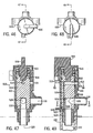
- Fig. 1 shows a fuel filter water separator 70 and will be only briefly described since it is also shown at 20 in U.S. Patent 5,855,772.
- Fuel filter water separator 70 includes a housing 72 closed by a threaded lid 74 and having a filter and water separating element 76 therein. Diesel fuel enters at fuel inlet 78, flows radially inwardly through annular filter element 76 to hollow interior 80 and then flows through fuel outlet 82 to the fuel injection system of internal combustion engine 84, such as a diesel engine.
- the housing includes a heater ring 86 for heating the diesel fuel to prevent it from coalescing in cold weather, a heater connector/thermostat assembly 88, and a water-in-fuel (WIF) sensor 90, all as is known in the prior art and as shown in the incorporated '772 patent.
- Housing 72 defines a water collection space 92 and a vent space 94.
- the housing has a wall 96 with a drain opening 98 therethrough for draining water from the water collection space.
- the wall has a vent opening 100 therethrough and permitting incoming air to replace outgoing water.
- the engine has a running condition wherein the fuel system including the fuel filter water separator is pressurized, and an off condition wherein the fuel system and fuel filter water separator is not pressurized.
- Drain valve 102 includes a housing 104, Fig. 2, mounted to fuel filter water separator housing 72 by bolts 106, 108, 110, 112, Figs. 2, 3, 12, 13, threaded into respective blind holes in increased thickness section 114 of the fuel filter water separator housing wall.
- the drain valve housing has a first port 116, Figs. 9 and 12 mating with vent opening 100.
- the drain valve housing has a second port 118, Figs. 9 and 13, mating with drain opening 98.
- the drain valve housing has a third port 120, Figs. 1 and 9, at the bottom thereof which is a combined vent and drain port and to which a drain hose 122, Figs. 2 and 3, may be connected at outer barbs 124 and retained by clamp 126.
- An actuator member 128 in drain valve housing 104 is actuatable between a closed position, Figs. 1-7, and an open position, Figs. 8-14.
- the closed position blocks communication of first port 116 with third port 120 and blocks communication of second port 118 with third port 120.
- the open position provides communication of first port 116 with third port 120 and provides communication of second port 118 with third port 120.
- actuator member 128 of drain valve 102 is actuated to the open position when the engine is in the noted off condition, collected water and vent air each flow through third port 120, but in opposite directions, Fig. 9, as shown at drain stream 130 and vent air stream 132.
- First port 116 draws air through the vent passage, to be described, from around drain stream 130 of collected water flowing in the opposite direction in third port 120.
- pressurized fuel spray from vent opening 100 and collected water from drain opening 98 of the fuel filter water separator housing each flow through third port 120 in the same direction as shown as fuel spray phantom arrow 134 and drain arrow 130, Fig. 9.
- a pressurized fuel vent stream 134 from first port 116 joins drain stream 130 from second port 118 at third port 120, and streams 134 and 130 flow in the same direction through port 120 to exit same, preferably through drain hose 122, Fig. 3.
- the drain valve has preferred vertical or gravitational orientation of the ports, particularly desirable for the noted non-pressurized drain cycle, i.e. with the engine in the noted off condition.
- Third port 120 is gravitationally below second port 118 which in turn is gravitationally below first port 116.
- Third port 120 is gravitationally below drain opening 98 which in turn is gravitationally below vent opening 100.
- actuator member 128 is a rotary piston 136 rotatable about a vertical axis 138.
- a vent passage 140, Figs. 2, 4, 9, 12 has a first portion 142, Figs. 4, 9, 12, extending radially through piston 136, relative to axis 138, and a second portion 144, Figs. 4, 9, 11, extending axially along a gap between piston 136 and drain valve housing 104.
- Fig. 9 such gap is between a flat surface 146, Figs. 11,12, on the outer surface of the piston, and a notched surface 148 on the inner cylindrical surface of the drain valve housing.
- First portion 142 of vent passage 140 extends between an upstream end 150 and a downstream end 152, Figs. 9 and 12.
- Second portion 144 of vent passage 140 extends between an upstream end 143, Fig. 9, and a downstream end 145.
- Downstream end 145 of second portion 144 is continuous with and in continuous communication with upstream end 150 of first portion 142, including in both of the noted open and closed positions.
- Downstream end 152 of first portion 142 communicates with first port 116 when piston 136 is in the noted open position, as shown in Figs. 9 and 12.
- Downstream end 152 is blocked from communication with first port 116 when piston 136 is in the noted closed position, Fig. 4.
- Piston 136 is preferably formed with a ball socket portion 156, Fig. 2, at vent port 140 to facilitate engagement with sealing grommet 154 and rotation of piston 136 while maintaining the seal.
- Upstream end 143 of second portion 144 of the vent passage is in communication with third port 120 in each of the open and closed positions of the piston.
- a drain passage 158, Figs. 2, 4, 9, 13, has a first portion 160, Figs. 4, 9, 13, extending radially in piston 136, relative to axis 138, and a second portion 162 extending axially in piston 136.
- First portion 160 extends between an upstream end 164 and a downstream end 166.
- Second portion 162 extends between an upstream end 168 and a downstream end 170.
- Upstream end 168 of second portion 162 is continuous with and in continuous communication with downstream end 166 of first potion 160 including in each of the noted open and closed positions of the piston.
- Downstream end 170 of second portion 162 is in communication with third port 120 in each of the open and closed positions of the piston.
- Upstream end 164 of first portion 160 is in communication with second port 118 when piston 136 is in the open position as shown in Figs. 9 and 13. Upstream end 164 is blocked from communication with second port 118 when piston 136 is in the closed position, as shown in Figs. 4 and 7.
- Piston 136 is provided with a second ball socket portion 174, Fig. 2, around drain passage 158 to facilitate and maintain the seal against sealing grommet 172 and to maintain such seal during rotation of piston 136.
- Drain valve 102 includes an manually engageable upper handle 176, Figs. 1 and 2, nonrotatably secured to piston 136 by roll pin 178.
- Coil spring 180 is a return spring and biases the valve handle to return to the closed position, Figs. 1-7, when released by the operator.
- Ball sockets 156 and 174 on piston 136 in cooperation with grommets 154 and 172, respectively, axially locate piston 136 in housing 104 and retain the piston in the housing. Additional retention is preferably provided by pin 182, Figs. 8, 14, engaging the underside of housing lip 184, Figs. 2, 14. In the closed position of the valve, Fig. 5, edge 185of the handle is stopped against shoulder 186 of housing 104.
- handle 176 When the valve is actuated to the open position, handle 176 is manually rotated by the operator 90° counter-clockwise to the position shown in Fig. 10, with handle edge 188 stopped against shoulder 190 of housing 104. O-ring 192, Figs. 4, 9, permits the noted rotation while sealing the interior of the valve.
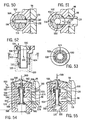
- Figs. 15-18 show a further embodiment and use like reference numerals from above where appropriate to facilitate understanding.
- the rotational stops for the opening and closing movements of the valve 200 are moved from the handle to the piston.
- piston 136 has an arcuate slot 201 with shoulders 202 and 204 at the ends thereof.
- piston 136 In the closed position of the valve, Fig. 15, piston 136 is in its clockwise rotated position, Fig. 16, with shoulder 204 stopped against radially inwardly projecting finger 206 formed on the inner cylindrical surface of housing 104.
- piston 136 In the open position of the valve, Fig. 17, piston 136 is rotated 90° counter-clockwise, Fig. 18, and shoulder 202 is stopped against finger 206.
- Drain valve 218 has a housing 220 and an actuator member provided by a rotary piston 222 rotatable about a vertical axis and having an upper manually engageable operator handle 224 nonrotatably secured to piston 222 by pin 226 and biased by spring 228 to return to the closed position, Figs. 19 and 20.
- shoulder 230 of arcuate slot 232 of piston 222 is stopped against radially inwardly projecting finger 234 of the inner cylindrical surface of housing 220.
- Piston 222 is rotated 90° counter-clockwise, as viewed in Figs. 20 and 22, to the open position, Fig. 21, with shoulder 236 of arcuate slot 232 stopped against finger 234.
- a vent passage 238, Fig. 21, has a first portion 240 extending radially in piston 222, relative to the noted vertical rotational axis of piston 222, and a second portion 242 extending axially in the piston.
- First portion 240 of the vent passage extends between an upstream end 244 and a downstream end 246.
- Second portion 242 of the vent passage extends between an upstream end 248 and a downstream end 250.
- Upstream end 244 of first portion 240 is continuous with and continuously communicates with downstream end 250 of second portion 242 of the vent passage including in each of the open and closed positions of the piston.
- Downstream end 246 of first portion 240 communicates with first port 116 when the piston is in the open position, Fig. 21, and is blocked from communication with first port 116 when the piston is in the closed position, Fig. 19.
- Upstream end 248 of second portion 242 communicates with third port 120 in each of the open and closed positions of the piston.
- Drain passage 252 has a first portion 254 extending radially in piston 222, and a second portion 256 extending axially in piston 222.
- First portion 254 extends between an upstream end 258 and a downstream end 260.
- Second portion 256 of the drain passage extends between an upstream end 262 and a downstream end 264.
- Downstream end 260 of first portion 254 is continuous with and in continuous communication with upstream end 262 of second portion 256 including in each of the open and closed positions of the piston.
- Upstream end 258 of first portion 254 communicates with second port 118 when the piston is in the open position, Fig. 21, and is blocked from communication with second port 118 when the piston is in the closed position, Fig. 19.
- Downstream end 264 of second portion 256 communicates with third port 120 in each of the open and closed positions of the piston, Figs. 21 and 19, respectively.
- Drain valve 278 has a housing 280 and an actuator member provided by a rotary piston 282 rotatable about a vertical rotation axis and having an upper handle 284 nonrotatably secured to piston 282 by pin 286 and biased to a closed position by return spring 288.
- a rotary piston 282 rotatable about a vertical rotation axis and having an upper handle 284 nonrotatably secured to piston 282 by pin 286 and biased to a closed position by return spring 288.
- shoulder 290, Fig. 25 of arcuate slot 292 on the outer surface of piston 282 is stopped against radially inwardly projecting finger 294 of the inner cylindrical surface of drain valve housing 280.
- shoulder 296 of arcuate slot 292 is stopped against finger 294.
- a vent passage 298, Fig. 26, has a first portion 300 extending radially through piston 282, relative to the noted vertical rotational axis, and a second portion 302 extending axially along a gap between piston 282 and drain valve housing 280.
- First portion 300 of the vent passage extends between an upstream end 304 and a downstream end 306.
- Second portion 302 of the vent passage extends between an upstream end 308 and a downstream end 310.
- Upstream end 304 of the first portion 300 is continuous with and continuously communicates with downstream end 310 of second portion 302 of the vent passage including in each of the open and closed positions of the piston.
- Downstream end 306 of first portion 300 communicates with first port 116 when the piston is in the open position, Figs. 26, 28, and is blocked from communication with first port 116 when the piston is in the closed position, Fig. 24.
- Upstream end 308 of second portion 302 communicates with third port 120 in each of the open and closed positions of the piston.
- Drain passage 312, Fig. 26, has a first portion 314 extending radially in the piston, and a second portion 316 extending axially in the piston.
- First portion 314 extends between an upstream end 318 and a downstream end 320.
- Second portion 316 of the drain passage extends between an upstream end 322 and a downstream end 324.
- Downstream end 320 of first portion 314 is continuous with and in continuous communication with upstream end 322 of second portion 316 of the drain passage including in each of the open and closed positions of the piston.
- Upstream end 318 of first portion 314 is in communication with second port 118 when the piston is in the open position, Figs. 26, 29, and is blocked from communication with second port 118 when the piston is in the closed position, Fig. 24.
- Downstream end 324 of second portion 316 is in communication with third port 120 in each of the open and closed positions of the piston.
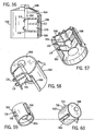
- Drain valve 340 includes a drain valve housing 342 and an actuator member provided by a rotary piston 344 rotatable about a vertical rotation axis and having an upper manually engageable handle 346 nonrotatably secured to piston 344 by pin 348 and biased to the closed position, Figs. 30, 34, 38, by return spring 350.
- a rotary piston 344 rotatable about a vertical rotation axis and having an upper manually engageable handle 346 nonrotatably secured to piston 344 by pin 348 and biased to the closed position, Figs. 30, 34, 38, by return spring 350.
- radially outwardly projecting finger 352, Fig. 31, on the outer surface of piston 344 is stopped against shoulder 354 of an arcuate slot 356 formed in the inner cylindrical surface of drain valve housing 342.
- Fig. 32, finger 352, Fig. 33 is stopped against shoulder 358 of arcuate slot 356.
- Drain valve 340 includes an upper cap 360, Fig. 30, thread mounted on housing 342.
- Spring 350 axially bears between cap 360 and a shoulder 362 on the piston and, in addition to the noted rotary bias, also supplies axial bias such that piston 344 is axially biased downwardly against a pair of lower O-ring seals 364 and 366, Figs. 30, 34, 37, 38.
- O-ring 364 is aligned with lower drain port 368 in lower horizontal wall 370 of housing 342.
- O-ring 366 is aligned with lower vent port 372 in horizontal wall 370.
- Ports 368 and 372 communicate with the noted third port 120 of the drain valve.
- Piston 344 is axially biased downwardly against O-rings 364 and 366 in sealing relation.
- a vent passage 374, Fig. 32 has a first portion 376 extending radially in piston 344, and a second portion 378 extending axially in the piston.
- First portion 376 extends between an upstream end 380 and a downstream end 382.
- Second portion 378 of the vent passage extends between an upstream end 386 and a downstream end 388.
- Upstream end 380 of first portion 376 is continuous with and in continuous communication with downstream end 388 of second portion 378 of the vent passage including in each of the open and closed positions of the piston.
- Downstream end 382 of first portion 376 is in communication with first port 116 in each of the open and closed positions of the piston, Figs. 32 and 30, respectively. This is accomplished by an arcuate groove 384, Figs.
- Drain passage 400 has a first portion 402 extending radially in piston 344, and a second portion 404 extending axially in piston 344.
- First portion 402 extends between an upstream end 406 and a downstream end 408.
- Second portion 404 of the drain passage extends between an upstream end 412 and a downstream end 414.
- Downstream end 408 of first portion 402 is continuous with and in continuous communication with upstream end 412 of second portion 404 of the drain passage including in each of the open and closed positions of the piston.
- Upstream end 406 of first portion 402 communicates with second port 118 in each of the open and closed positions of the piston, Figs. 32 and 30, respectively.
- vent and drain passage arcuate grooves 384 and 410 may be formed in the inner cylindrical surface of the drain valve housing.
- Downstream end 414 of second portion 404 communicates with third port 120 through O-ring 364 and drain port 368 when the piston is in the open position, Figs. 32 and 37.
- Downstream end 414 of second portion 404 is blocked from communication with drain port 368 and third port 120 when the piston is in the closed position, Figs. 30 and 38.
- Drain valve 430 includes a drain valve housing 432 having an actuator member provided by a rotary piston 434 rotatable about a vertical rotation axis and having an upper manually engageable handle 436 nonrotatably secured to piston 434 by pin 438 and biased to the closed position, Figs. 39, 45, by return spring 440.
- a bottom end cap 442 is mounted to the housing in threaded relation to axially locate and retain the piston in the housing and to provide an axial stop for lower springs 444 and 446, Fig.
- a lower cup-shaped retainer member 456 has respective vent and drain ports 458 and 460 therethrough aligned with respective vent and drain ports 452 and 454 and the respective openings in respective annular seals 448 and 450 and the respective hollow interiors of springs 444 and 446.
- Springs 444 and 446 bear axially between retainer member 456 and respective annular seals 448 and 450.
- Retainer member 456 is held in place by lower end cap 442 and is sealed to housing 432 by O-ring 462.
- vent air 132 flows upwardly through third port 120, vent ports 458 and 452 then through portions 464 and 466, Fig. 41 of vent passage 468 to first port 116 communicating with vent opening 100.
- the collected water drain stream 130 flows from drain opening 98 to second port 118 then through portions 470 and 472 of drain passage 474 then through drain ports 454 and 460 to third port 120.
- Drain valve 500 includes a drain valve housing 502 and an actuator member provided by a rotary piston 504 rotatable about a vertical rotation axis and having an upper manually engageable handle 506 nonrotatably secured to piston 504 in keyed relation, such as square fit 508 or the like, and biased to the closed position, Fig. 47, by return spring 510.
- Vent passage 512, Fig. 49 extends from first port 116 radially at 514 in the piston then axially at 516 in the piston through lower vent port 518 through bottom wall 520 of the housing when the piston is in the open position, Figs. 49, 50.
- Vent port 518 in turn communicates with annular passage 522 around drain port 524 at third port 120.
- Axial vent passage portion 516 is blocked from communication with vent port 518 in bottom wall 520 when the piston is in the closed position, Fig. 47.
- Radial portion 514 of the vent passage is blocked from communication with first port 116 when the piston is in the closed position, Fig. 47.
- Drain passage 526 has a portion 528 extending radially from second port 118 and a portion 530 extending axially and communication with drain port 524 and third port 120 in each of the open and closed positions of the piston, Figs. 49 and 47 respectively.
- O-rings 532 and 534 permit the noted rotation and seal the interior of the valve.
- Additional O-rings 536 and 538 are provided around respective portions 514 and 528 of respective vent and drain passages 512 and 526.
- Drain valve 550 includes a drain valve housing 552 and an actuator member provided by a reciprocal plunger 554 preferably reciprocal along a vertical reciprocation axis.
- a vent passage 556 has a first portion 558 extending from first port 116 radially in drain valve housing 552, relative to the noted reciprocation axis 560, a second portion 562 extending axially in housing 552 along plunger 554, a third portion 564 extending radially in housing 552, a fourth portion 566 extending axially in housing 552, and a fifth portion 568 extending radially in housing 552.
- Radial portions 558 and 564 are joined by axial portion 562 when plunger 554 is in the open position, Fig. 55.
- Axial portion 566 is radially spaced from axial portion 562. Vent air 132 through the vent passage flows from third port 120 through portion 568 then axially through portion 566 then radially through portion 564 then axially through portion 562 then radially through portion 558 to first port 116 and vent opening 100.
- Housing 552 has a drain chamber 570 and a vent chamber 572 spaced from each other by a dividing wall 574. Plunger 554 reciprocates in the vent and drain chambers between open and closed positions, Figs. 55 and 54, respectively. In the open position, Fig.
- Drain passage 576 has a first portion 578 extending radially in drain valve housing 552, relative to axis 560, and a second portion 580 extending axially along plunger 554 to third port 120. O-ring seals 582,584,586 are provided along the plunger for sealing the respective passages.
- a self-biasing molded rubber or plastic cap 588 is secured to the top of the plunger and biases the plunger upwardly to the closed position, Fig. 54. To open to valve, the operator manually pushes down on cap 588 as shown at arrow 589, Fig. 55.
- a return spring 590 may be provided to bias plunger 554 upwardly to the closed position.
- Drain valve 600 includes a drain valve housing 602 having an actuator member provided by a rotary piston 604 rotatable about a vertical rotation axis and having an upper manually engageable handle 606 nonrotatably secured to piston 604 by pin 608 and biased by return spring 610, as above.
- Vent passage 612 has a first portion 614 extending radially through piston 604, relative to the noted rotation axis, and a second portion 616 extending axially through housing 602.
- the operation of drain valve 600 is like that described above except that the axial portion 616 of the vent passage extends through the drain valve housing 602 rather than extending along a gap between piston 604 and housing 602, and rather than extending through piston 604.
Landscapes
- Chemical & Material Sciences (AREA)
- Chemical Kinetics & Catalysis (AREA)
- Engineering & Computer Science (AREA)
- Physics & Mathematics (AREA)
- Thermal Sciences (AREA)
- Combustion & Propulsion (AREA)
- Mechanical Engineering (AREA)
- General Engineering & Computer Science (AREA)
- Multiple-Way Valves (AREA)
- Self-Closing Valves And Venting Or Aerating Valves (AREA)
- Filtration Of Liquid (AREA)
- Separating Particles In Gases By Inertia (AREA)
Claims (8)
- Soupape de vidange (102, 200, 218, 278, 340, 430, 500, 600) pour un séparateur d'eau (70) de filtre à carburant pour un moteur à combustion interne (84), ledit séparateur d'eau (70) de filtre à carburant ayant un boîtier (72) définissant un espace de collecte d'eau (92) et un espace d'aérage (94), le boîtier (72) ayant une paroi (96) avec une ouverture de vidange (98) la traversant pour vidanger l'eau dudit espace de collecte d'eau (92), et ayant une ouverture d'aérage (100) la traversant et permettant à l'air entrant de remplacer l'eau sortant, ledit moteur (84) ayant un mode de fonctionnement dans lequel ledit séparateur d'eau (70) de filtre à carburant est pressurisé, ledit moteur (84) ayant un mode arrêté lorsque ledit séparateur d'eau (70) de filtre à carburant n'est pas pressurisé, ladite soupape de vidange (102, 200, 218, 278, 340, 430, 500, 600) comprenant un boîtier (104, 220, 280, 342, 432, 502, 602) pouvant être monté sur ledit boîtier (72) de séparateur d'eau de filtre à carburant et ayant un premier orifice (116) destiné à s'accoupler avec ladite ouverture d'aérage (100), un deuxième orifice (118) destiné à s'accoupler avec ladite ouverture de vidange (98), et un troisième orifice (120), et un actionneur (128) dans ledit boîtier de la soupape de vidange (104, 220, 280, 342, 432, 502, 602) pouvant être actionné entre une position fermée bloquant toute communication dudit premier orifice (116) avec ledit troisième orifice (120) et bloquant toute communication dudit deuxième orifice (118) avec ledit troisième orifice (120), et une position ouverte assurant la communication dudit premier orifice (116) avec ledit troisième orifice (120) et assurant la communication dudit deuxième orifice (118) avec ledit troisième orifice (120) de telle sorte que si ledit actionneur (128) de ladite soupape de vidange (102, 200, 218, 278, 340, 430, 500, 600) est actionné dans ladite position ouverte lorsque ledit moteur (84) est dans ledit mode arrêté, l'eau collectée et l'air d'aérage s'écoulent chacun à travers ledit troisième orifice (120) dans des directions opposées, caractérisée en ce que ledit actionneur (128) est un piston rotatif (136, 222, 282, 344, 434, 504, 604) pouvant tourner autour d'un axe (138) et une communication entre lesdits premier et deuxième orifices (116 et 118) avec ledit troisième orifice s'effectue par un passage respectif (140, 238, 298, 374, 468, 512, 612 ou 158, 252, 312, 400, 474, 526), au moins l'un desdits passages (140, 238, 298, 374, 468, 512, 612, 158, 252, 312, 400, 474, 526) ayant une première portion (142, 240, 300, 376, 466, 514, 614, 160, 254, 314, 402, 470, 528) s'étendant radialement dans ou à travers ledit piston rotatif (136, 222, 282, 344, 434, 504, 604), par rapport audit axe (138), et une deuxième portion (144, 162, 242, 256, 302, 316, 378, 404, 464, 472, 516, 530, 616) s'étendant axialement par rapport audit axe de rotation (138) dudit piston rotatif (136, 222, 282, 344, 434, 504, 604).
- Soupape de vidange (102, 200, 218, 278, 340, 430, 500, 600) selon la revendication 1, dans laquelle ledit au moins un passage est un passage d'aérage (140, 238, 298, 374, 468, 512, 612) dont ladite deuxième portion (242, 378, 464, 516) s'étend axialement dans ledit piston (136) ou (144, 302) le long d'un espace entre ledit piston (136) et ledit boîtier de soupape de vidange (104), ou s'étend à travers ledit boîtier de soupape de vidange (104).
- Soupape de vidange (102, 200, 218, 278, 340, 430, 500, 600) selon la revendication 1, dans laquelle ledit au moins un passage est un passage de vidange (158, 252, 312, 400, 474, 526) dont ladite deuxième portion (162, 256, 316, 404, 472, 530) s'étend axialement dans ledit piston (136).
- Soupape de vidange (102, 200, 218, 278, 340, 430, 500, 600) selon la revendication 1, dans laquelle ledit au moins un passage est un passage d'aérage (140, 238, 298, 374, 468, 512, 612), ladite soupape de vidange (102, 200, 218, 278, 340, 430, 500, 600) ayant un passage de vidange (158, 252, 312, 400, 474, 526) avec une première portion (160, 254, 314, 402, 470, 528) s'étendant radialement, par rapport audit axe (138), et une deuxième portion (162, 256, 316, 404, 472, 530) s'étendant axialement.
- Soupape de vidange (102, 200, 218, 278, 340, 430, 500, 600) selon la revendication 1, ayant un passage de vidange (158, 252, 312, 400, 474, 526) communiquant entre lesdits deuxième et troisième orifices (118 et 120) à des extrémités amont et aval (164 et 170, 258 et 264, 318 et 324, 406 et 414), respectivement, ladite soupape de vidange (102, 200, 218, 278, 340, 430, 500, 600) ayant un passage d'aérage (140, 238, 298, 374, 468, 512, 612) communiquant entre lesdits troisième et premier orifices (120 et 116) à des extrémités amont et aval (143 et 152, 246 et 248, 306 et 308, 382 et 386), respectivement, ledit passage d'aérage (140, 238, 298, 374, 468, 512, 612) ayant une entrée à ladite extrémité amont (143, 248, 308, 386) dudit passage d'aérage (140, 238, 298, 374, 468, 512, 612), ledit passage de vidange (158, 252, 312, 400, 474, 526) ayant une sortie à ladite extrémité aval (170, 264, 324, 414) dudit passage de vidange (158, 252, 312, 400, 474, 526), ladite entrée du passage d'aérage étant dans le même orifice, à savoir ledit troisième orifice (120), que ladite sortie du passage de vidange.
- Procédé pour faire fonctionner un moteur à combustion interne (84) ayant un séparateur d'eau (70) de filtre à carburant muni d'une soupape de vidange (102, 200, 218, 278, 340, 430, 500, 600) selon la revendication 1 ou 5, dans lequel la pression de carburant dans ledit séparateur d'eau (70) de filtre à carburant dans ledit mode de fonctionnement dudit moteur (84) fournit du carburant sous pression au niveau de ladite ouverture d'aérage (100), de sorte que si ledit piston rotatif (136) de ladite soupape de vidange (102, 200, 218, 278, 340, 430, 500, 600) est actionné dans ladite position ouverte lorsque ledit moteur (84) est dans ledit mode de fonctionnement, un jet de carburant sous pression provenant de ladite ouverture d'aérage (100) et de l'eau collectée provenant de ladite ouverture de vidange (98) dudit boîtier (72) de séparateur d'eau de filtre à carburant s'écoulent chacun à travers ledit troisième orifice (120) dans la même direction.
- Procédé pour faire fonctionner un moteur à combustion interne (84) ayant un séparateur d'eau (70) de filtre à carburant muni d'une soupape de vidange (102, 200, 218, 278, 340, 430, 500, 600) selon la revendication 5, dans lequel, dans ledit mode arrêté dudit moteur (84), avec ledit séparateur d'eau (70) de filtre à carburant non pressurisé, ledit premier orifice (116) aspire de l'air dudit passage d'aérage (140, 238, 298, 374, 468, 512, 612) depuis le côté du courant de vidange (130) de ladite eau collectée s'écoulant dans la direction opposée dans ledit troisième orifice (120).
- Procédé pour faire fonctionner un moteur à combustion interne (84) ayant un séparateur d'eau (70) de filtre à carburant muni d'une soupape de vidange (102, 200, 218, 278, 340, 430, 500, 600) selon la revendication 6, dans lequel, dans ledit mode arrêté dudit moteur (84), avec ledit séparateur d'eau (70) de filtre à carburant non pressurisé, ledit premier orifice (116) aspire de l'air à travers ledit passage d'aérage (140, 238, 298, 374, 468, 512, 612) depuis les environs du courant de vidange (130) de ladite eau collectée s'écoulant dans la direction opposée dans ledit troisième orifice (120), et de telle sorte que si ladite soupape de vidange (102, 200, 218, 278, 340, 430, 500, 600) est actionnée dans ladite position ouverte dans ledit mode de fonctionnement dudit moteur (84) avec ledit séparateur d'eau (70) de filtre à carburant pressurisé, un courant d'aérage de carburant pressurisé (134) provenant dudit premier orifice (116) rejoint ledit courant de vidange (130) provenant dudit deuxième orifice (118) au niveau dudit troisième orifice (120) et s'écoule à travers ledit troisième orifice (120) dans la même direction que ledit courant de vidange (130).
Applications Claiming Priority (2)
| Application Number | Priority Date | Filing Date | Title |
|---|---|---|---|
| US09/412,713 US6358416B1 (en) | 1999-10-05 | 1999-10-05 | Drain valve for fuel filter water separator |
| US412713 | 1999-10-05 |
Publications (2)
| Publication Number | Publication Date |
|---|---|
| EP1090667A1 EP1090667A1 (fr) | 2001-04-11 |
| EP1090667B1 true EP1090667B1 (fr) | 2007-03-07 |
Family
ID=23634152
Family Applications (1)
| Application Number | Title | Priority Date | Filing Date |
|---|---|---|---|
| EP20000308733 Expired - Lifetime EP1090667B1 (fr) | 1999-10-05 | 2000-10-04 | Soupape de vidange pour un séparateur d'eau de filtre à carburant |
Country Status (6)
| Country | Link |
|---|---|
| US (2) | US6358416B1 (fr) |
| EP (1) | EP1090667B1 (fr) |
| JP (1) | JP2001140723A (fr) |
| AU (1) | AU768580B2 (fr) |
| BR (1) | BR0004328A (fr) |
| DE (1) | DE60033754T2 (fr) |
Families Citing this family (32)
| Publication number | Priority date | Publication date | Assignee | Title |
|---|---|---|---|---|
| US6358416B1 (en) * | 1999-10-05 | 2002-03-19 | Fleetguard, Inc. | Drain valve for fuel filter water separator |
| US6237628B1 (en) * | 2000-07-10 | 2001-05-29 | Fleetguard, Inc. | Self-centering water drain valve |
| US6430842B1 (en) * | 2001-05-09 | 2002-08-13 | Carter Day International, Inc. | Assembly for supporting a rotating structure |
| US6565746B1 (en) * | 2002-04-30 | 2003-05-20 | Dana Corporation | One-piece self-venting drain valve |
| JP3804949B2 (ja) * | 2002-11-12 | 2006-08-02 | トヨタ紡織株式会社 | 流体フィルタ及びそのドレン機構、流体フィルタに使用されるドレン用冶具並びに流体フィルタのドレン方法 |
| CA2557711C (fr) * | 2004-03-02 | 2012-11-27 | Ds Smith Plastics Limited | Robinet pour liquide a purge d'air |
| US20070034580A1 (en) * | 2005-08-11 | 2007-02-15 | Stein Matthew L | Fluid filter arrangement including valve arrangement and methods |
| US7717092B2 (en) | 2006-08-14 | 2010-05-18 | Cummins Filtration Ip Inc. | Fuel system with air venting and fuel anti-drainback |
| US8272252B2 (en) * | 2006-10-10 | 2012-09-25 | Porous Materials, Inc. | Pore structure characterization of filtration cartridges at specific locations along cartridge length |
| US7614279B2 (en) * | 2006-10-10 | 2009-11-10 | Porous Materials, Inc. | Determination of pore structure characteristics of filtration cartridges as a function of cartridge length |
| JP4784551B2 (ja) * | 2007-05-09 | 2011-10-05 | トヨタ紡織株式会社 | 流体フィルタ |
| US8496816B2 (en) * | 2007-09-24 | 2013-07-30 | Cummins Filtration Ip, Inc. | Modular fuel filter assembly |
| CN105545551B (zh) * | 2008-09-24 | 2018-09-21 | 康明斯过滤Ip公司 | 用于过滤器组件的流体传感器模块和过滤器组件 |
| US8360251B2 (en) | 2008-10-08 | 2013-01-29 | Cummins Filtration Ip, Inc. | Multi-layer coalescing media having a high porosity interior layer and uses thereof |
| US7770526B2 (en) * | 2008-11-03 | 2010-08-10 | Draco Spring Mfg. Co., Inc | Railcar man-way cover lift-assist system |
| US20100133205A1 (en) * | 2008-12-03 | 2010-06-03 | International Truck Intellectual Property Company, Llc | Remote Actuator for a Fuel Water Separator on a Vehicle |
| US9332969B2 (en) | 2009-01-06 | 2016-05-10 | Carefusion 207, Inc. | Fluid flow control apparatus and patient fluid sampling method |
| DE112010002027B4 (de) * | 2009-05-15 | 2021-12-09 | Cummins Filtration Ip, Inc. | Koaleszenzabscheider und Verwendung eines Koaleszenzabscheiders in einem Koaleszenzsystem |
| CN102656393B (zh) * | 2009-09-30 | 2015-12-09 | 康明斯过滤Ip公司 | 辅助的o型圈沟槽 |
| US10058808B2 (en) | 2012-10-22 | 2018-08-28 | Cummins Filtration Ip, Inc. | Composite filter media utilizing bicomponent fibers |
| US9527016B2 (en) | 2014-01-24 | 2016-12-27 | Caterpillar Inc. | Filter element having vent tube and filter assembly |
| US20170335812A1 (en) * | 2014-09-26 | 2017-11-23 | Cummins Filtration Ip, Inc. | Auto drain system for vacuum side fuel water separators |
| DE102014114486B4 (de) * | 2014-10-07 | 2021-01-28 | Norma Germany Gmbh | Ablaufstutzen |
| BR112017021385B1 (pt) | 2015-04-09 | 2022-05-03 | Parker-Hannifin Corporation | Sistema e método para remover água acumulada de um conjunto de filtro e cartucho de filtro |
| WO2017040367A1 (fr) * | 2015-08-31 | 2017-03-09 | Cummins Filtration Ip, Inc. | Joint d'orifice de filtre |
| DE102016005270B4 (de) | 2016-04-29 | 2019-09-05 | Mann+Hummel Gmbh | Ablasssteuerungsvorrichtung für ein Filtersystem sowie Filtersystem mit einer Ablasssteuerungsvorrichtung |
| DE102016005271B4 (de) | 2016-04-29 | 2019-10-02 | Mann+Hummel Gmbh | Ablasssteuerungsvorrichtung für ein Filtersystem sowie Filtersystem mit einer Ablasssteuerungsvorrichtung |
| DE112017002974T5 (de) | 2016-07-19 | 2019-03-07 | Cummins Filtration Ip, Inc. | Koaleszer mit perforierter schicht |
| US10344883B2 (en) * | 2016-11-02 | 2019-07-09 | Schaeffler Technologies AG & Co. KG | Modular electro-mechanical rotary valve |
| US11420141B2 (en) | 2017-08-18 | 2022-08-23 | Cummins Filtration Ip, Inc. | Fuel filter cartridge with keyed profile |
| KR102335988B1 (ko) * | 2017-11-29 | 2021-12-07 | 현대자동차주식회사 | 연료필터의 수분 및 우레아 드레인장치 및 드레인방법 |
| DE112021001295T5 (de) * | 2020-02-28 | 2023-03-02 | Cummins Filtration Inc | Nicht belüftetes, halbautomatisches wasserablassventilsystem |
Family Cites Families (40)
| Publication number | Priority date | Publication date | Assignee | Title |
|---|---|---|---|---|
| US410448A (en) | 1889-09-03 | Drip-cock for locomotive-cylinders | ||
| US253405A (en) | 1882-02-07 | Steam-cylinder cock | ||
| US807285A (en) | 1904-07-18 | 1905-12-12 | Andrew J Ketelsen | Faucet. |
| US928813A (en) | 1908-03-20 | 1909-07-20 | Brewery And Distillery Equipment Corp | Beer-tapper. |
| US1711537A (en) | 1928-05-14 | 1929-05-07 | L S Jones | Detachable siphon device |
| US2054488A (en) | 1935-06-18 | 1936-09-15 | Russell W Sinks | Liquid evacuating system |
| US2113046A (en) | 1936-11-19 | 1938-04-05 | Alphonse A Burnand Jr | Self-venting valve |
| US2878829A (en) | 1956-03-16 | 1959-03-24 | Union Tank Car Co | Valve mechanism |
| US3005475A (en) | 1960-06-13 | 1961-10-24 | Jr Richard W Beall | Combined liquid dispensing and air venting apparatus |
| US3234958A (en) | 1963-07-05 | 1966-02-15 | Watts Regulator Co | Valve for washing machines |
| US3322280A (en) | 1964-06-18 | 1967-05-30 | Fram Corp | Liquid fuel filter and water separator |
| US3405601A (en) | 1966-03-23 | 1968-10-15 | Autoquip Corp | Single rotary valve for hydraulic fluid and air |
| US3450157A (en) | 1967-07-31 | 1969-06-17 | John E Hewson | Valve manifold |
| US3768659A (en) | 1971-10-27 | 1973-10-30 | Tenneco Inc | Drain valve for fuel filter |
| US3894559A (en) | 1974-03-28 | 1975-07-15 | Leland Q Depuy | Manifold valve |
| US3980457A (en) | 1975-02-18 | 1976-09-14 | International Basic Economy Corporation | Pneumatic filter/separator with magnetically controlled fluid valve |
| US4010101A (en) | 1976-07-19 | 1977-03-01 | Cyril Davey | Liquid trap |
| US4334989A (en) | 1980-12-29 | 1982-06-15 | Chrysler Corporation | Fuel-water separator with piston-check valve water disposal to evaporator |
| US4440193A (en) | 1981-11-23 | 1984-04-03 | Cummins Engine Company, Inc. | Valve assembly |
| US4515690A (en) | 1982-08-06 | 1985-05-07 | Nissan Motor Company, Limited | Fuel supply system for diesel engines |
| US4437986A (en) * | 1982-09-22 | 1984-03-20 | Fram Corporation | Separating device and cartridge therefor |
| US4500425A (en) | 1984-06-13 | 1985-02-19 | Allied Corporation | Pump valve for liquid separator |
| US4611627A (en) * | 1985-02-07 | 1986-09-16 | Donaldson Company, Inc. | Self-venting drain valve |
| US4602657A (en) | 1985-02-11 | 1986-07-29 | Anderson-Greenwood & Co. | Valve manifold for a differential pressure transmitter |
| US4724074A (en) | 1985-10-07 | 1988-02-09 | Parker Hannifin Corporation | Self-venting drain assembly |
| US4753266A (en) | 1986-04-08 | 1988-06-28 | Cummins Engine Company, Inc. | Valve assembly |
| US4877218A (en) | 1986-05-15 | 1989-10-31 | Design Improvement Corporation | Drain valve device |
| US4708171A (en) | 1986-11-14 | 1987-11-24 | J. A. Baldwin Manufacturing Co. | Drain valve |
| US4855041A (en) * | 1987-04-24 | 1989-08-08 | Parker Hannifin Corporation | Fluid filter drain assembly |
| DE3723696A1 (de) | 1987-07-17 | 1989-03-09 | Desch Kurt Michael | Mit zwei kugeln aufgebautes zentralsteuerventil |
| US4846223A (en) | 1988-11-16 | 1989-07-11 | Dana Corporation | Self-venting spool valve assembly |
| US4922960A (en) | 1989-07-13 | 1990-05-08 | Parker-Hannifin Corporation | Self venting drain valve |
| US5029606A (en) | 1989-12-05 | 1991-07-09 | Kuhlthau Jr Paul W | Wall-mounted hook-up assemblies for washing machine and lavatory |
| US4951918A (en) | 1990-04-06 | 1990-08-28 | Therm-O-Disc, Incorporated | Valve vent |
| US4976285A (en) | 1990-05-30 | 1990-12-11 | Parker Hannifin Corporation | Universal self-venting drain valve |
| US5144978A (en) | 1992-01-31 | 1992-09-08 | Baldwin Filters, Inc. | Self-venting drain valve |
| US5433242A (en) | 1993-10-12 | 1995-07-18 | The Hoover Company | Pressure activated dispensing valve |
| US5606989A (en) | 1995-06-01 | 1997-03-04 | Dana Corporation | Self-venting valve arrangement |
| US5855772A (en) | 1996-11-01 | 1999-01-05 | Fleetguard, Inc. | Fuel filter and water separator apparatus with heater |
| US6358416B1 (en) * | 1999-10-05 | 2002-03-19 | Fleetguard, Inc. | Drain valve for fuel filter water separator |
-
1999
- 1999-10-05 US US09/412,713 patent/US6358416B1/en not_active Expired - Lifetime
-
2000
- 2000-09-07 AU AU56572/00A patent/AU768580B2/en not_active Ceased
- 2000-09-20 BR BR0004328A patent/BR0004328A/pt not_active Application Discontinuation
- 2000-09-26 JP JP2000292702A patent/JP2001140723A/ja active Pending
- 2000-10-04 DE DE2000633754 patent/DE60033754T2/de not_active Expired - Lifetime
- 2000-10-04 EP EP20000308733 patent/EP1090667B1/fr not_active Expired - Lifetime
-
2001
- 2001-11-30 US US09/997,795 patent/US6533935B2/en not_active Expired - Lifetime
Also Published As
| Publication number | Publication date |
|---|---|
| US6358416B1 (en) | 2002-03-19 |
| BR0004328A (pt) | 2001-06-19 |
| US20020036163A1 (en) | 2002-03-28 |
| EP1090667A1 (fr) | 2001-04-11 |
| AU5657200A (en) | 2001-04-12 |
| JP2001140723A (ja) | 2001-05-22 |
| DE60033754T2 (de) | 2007-11-22 |
| US6533935B2 (en) | 2003-03-18 |
| AU768580B2 (en) | 2003-12-18 |
| DE60033754D1 (de) | 2007-04-19 |
Similar Documents
| Publication | Publication Date | Title |
|---|---|---|
| EP1090667B1 (fr) | Soupape de vidange pour un séparateur d'eau de filtre à carburant | |
| US5614091A (en) | Fuel filter master module with optional diverter capability | |
| CA2435926C (fr) | Dispositif de filtration de liquide | |
| EP0658362B1 (fr) | Maítre-filtre modulaire pour carburant avec système de détournement facultatif | |
| CA2177886C (fr) | Robinet autoventile | |
| US6019890A (en) | Fuel filter with hand primer | |
| CN112023510B (zh) | 用于引导流体通过过滤器的流罩以及方法 | |
| MXPA02003228A (es) | Conjunto de filtro de fluido de paso dual y elemento para el mismo. | |
| CN108472563B (zh) | 过滤元件和过滤系统 | |
| RU2743081C2 (ru) | Запорный механизм для очистки фильтрующего элемента | |
| US20080053886A1 (en) | Liquid filter element having keys | |
| WO1990007666A1 (fr) | Ensemble a soupape de purge a decharge automatique | |
| US20140124459A1 (en) | No filter no run feature for filter | |
| US7335300B1 (en) | Fluid filter element | |
| WO2007021874A1 (fr) | Systeme de filtre pour fluides comprenant un systeme de soupapes et procedes correspondants | |
| US7946430B2 (en) | Filter with protruding member for engaging valve in head | |
| EP1776993B1 (fr) | Filtre à gazole | |
| US20080283464A1 (en) | Filter assembly with valve requiring compliant filter for open flow path | |
| KR20100129205A (ko) | 필터장치 | |
| US6722507B2 (en) | Valve for fluid filter | |
| CA2462772A1 (fr) | Appareil filtrant et methode de fonctionnement | |
| EP1165203B1 (fr) | Filtre a combustible | |
| KR20220159951A (ko) | 지지 베어링을 갖는 블로바이 가스 여과 조립체 | |
| US20200078709A1 (en) | Fluid filter assembly with an improved valve assembly | |
| JPS59141761A (ja) | 燃料コシ器のエア抜き装置 |
Legal Events
| Date | Code | Title | Description |
|---|---|---|---|
| PUAI | Public reference made under article 153(3) epc to a published international application that has entered the european phase |
Free format text: ORIGINAL CODE: 0009012 |
|
| AK | Designated contracting states |
Kind code of ref document: A1 Designated state(s): DE FR GB |
|
| AX | Request for extension of the european patent |
Free format text: AL;LT;LV;MK;RO;SI |
|
| 17P | Request for examination filed |
Effective date: 20011004 |
|
| AKX | Designation fees paid |
Free format text: DE FR GB |
|
| 17Q | First examination report despatched |
Effective date: 20030704 |
|
| GRAP | Despatch of communication of intention to grant a patent |
Free format text: ORIGINAL CODE: EPIDOSNIGR1 |
|
| GRAS | Grant fee paid |
Free format text: ORIGINAL CODE: EPIDOSNIGR3 |
|
| GRAA | (expected) grant |
Free format text: ORIGINAL CODE: 0009210 |
|
| AK | Designated contracting states |
Kind code of ref document: B1 Designated state(s): DE FR GB |
|
| REG | Reference to a national code |
Ref country code: GB Ref legal event code: FG4D |
|
| REF | Corresponds to: |
Ref document number: 60033754 Country of ref document: DE Date of ref document: 20070419 Kind code of ref document: P |
|
| EN | Fr: translation not filed | ||
| PLBE | No opposition filed within time limit |
Free format text: ORIGINAL CODE: 0009261 |
|
| STAA | Information on the status of an ep patent application or granted ep patent |
Free format text: STATUS: NO OPPOSITION FILED WITHIN TIME LIMIT |
|
| 26N | No opposition filed |
Effective date: 20071210 |
|
| PG25 | Lapsed in a contracting state [announced via postgrant information from national office to epo] |
Ref country code: FR Free format text: LAPSE BECAUSE OF FAILURE TO SUBMIT A TRANSLATION OF THE DESCRIPTION OR TO PAY THE FEE WITHIN THE PRESCRIBED TIME-LIMIT Effective date: 20071026 |
|
| GBPC | Gb: european patent ceased through non-payment of renewal fee |
Effective date: 20071004 |
|
| PG25 | Lapsed in a contracting state [announced via postgrant information from national office to epo] |
Ref country code: FR Free format text: LAPSE BECAUSE OF FAILURE TO SUBMIT A TRANSLATION OF THE DESCRIPTION OR TO PAY THE FEE WITHIN THE PRESCRIBED TIME-LIMIT Effective date: 20070307 Ref country code: GB Free format text: LAPSE BECAUSE OF NON-PAYMENT OF DUE FEES Effective date: 20071004 |
|
| REG | Reference to a national code |
Ref country code: DE Ref legal event code: R082 Ref document number: 60033754 Country of ref document: DE Representative=s name: ANDRAE WESTENDORP PATENTANWAELTE PARTNERSCHAFT, DE Ref country code: DE Ref legal event code: R082 Ref document number: 60033754 Country of ref document: DE Representative=s name: FRIESE GOEDEN, DE Ref country code: DE Ref legal event code: R082 Ref document number: 60033754 Country of ref document: DE Representative=s name: FRIESE GOEDEN PATENTANWAELTE PARTGMBB, DE |
|
| REG | Reference to a national code |
Ref country code: DE Ref legal event code: R082 Ref document number: 60033754 Country of ref document: DE Representative=s name: FRIESE GOEDEN, DE Ref country code: DE Ref legal event code: R082 Ref document number: 60033754 Country of ref document: DE Representative=s name: FRIESE GOEDEN PATENTANWAELTE PARTGMBB, DE |
|
| PGFP | Annual fee paid to national office [announced via postgrant information from national office to epo] |
Ref country code: DE Payment date: 20171027 Year of fee payment: 18 |
|
| REG | Reference to a national code |
Ref country code: DE Ref legal event code: R119 Ref document number: 60033754 Country of ref document: DE |
|
| PG25 | Lapsed in a contracting state [announced via postgrant information from national office to epo] |
Ref country code: DE Free format text: LAPSE BECAUSE OF NON-PAYMENT OF DUE FEES Effective date: 20190501 |