EP1089903B1 - Capacite hydraulique a absorption controlee en pression - Google Patents
Capacite hydraulique a absorption controlee en pression Download PDFInfo
- Publication number
- EP1089903B1 EP1089903B1 EP99923689A EP99923689A EP1089903B1 EP 1089903 B1 EP1089903 B1 EP 1089903B1 EP 99923689 A EP99923689 A EP 99923689A EP 99923689 A EP99923689 A EP 99923689A EP 1089903 B1 EP1089903 B1 EP 1089903B1
- Authority
- EP
- European Patent Office
- Prior art keywords
- hollow body
- volume
- wall
- zone
- thickness
- Prior art date
- Legal status (The legal status is an assumption and is not a legal conclusion. Google has not performed a legal analysis and makes no representation as to the accuracy of the status listed.)
- Expired - Lifetime
Links
- 238000010521 absorption reaction Methods 0.000 title description 2
- 239000012530 fluid Substances 0.000 claims abstract description 24
- 239000000463 material Substances 0.000 claims description 3
- 239000000543 intermediate Substances 0.000 description 2
- 230000007423 decrease Effects 0.000 description 1
- 230000003247 decreasing effect Effects 0.000 description 1
- 238000010586 diagram Methods 0.000 description 1
- 239000013013 elastic material Substances 0.000 description 1
- 239000013536 elastomeric material Substances 0.000 description 1
- 238000003912 environmental pollution Methods 0.000 description 1
- 238000000034 method Methods 0.000 description 1
- 238000004088 simulation Methods 0.000 description 1
Images
Classifications
-
- B—PERFORMING OPERATIONS; TRANSPORTING
- B60—VEHICLES IN GENERAL
- B60T—VEHICLE BRAKE CONTROL SYSTEMS OR PARTS THEREOF; BRAKE CONTROL SYSTEMS OR PARTS THEREOF, IN GENERAL; ARRANGEMENT OF BRAKING ELEMENTS ON VEHICLES IN GENERAL; PORTABLE DEVICES FOR PREVENTING UNWANTED MOVEMENT OF VEHICLES; VEHICLE MODIFICATIONS TO FACILITATE COOLING OF BRAKES
- B60T13/00—Transmitting braking action from initiating means to ultimate brake actuator with power assistance or drive; Brake systems incorporating such transmitting means, e.g. air-pressure brake systems
- B60T13/10—Transmitting braking action from initiating means to ultimate brake actuator with power assistance or drive; Brake systems incorporating such transmitting means, e.g. air-pressure brake systems with fluid assistance, drive, or release
- B60T13/12—Transmitting braking action from initiating means to ultimate brake actuator with power assistance or drive; Brake systems incorporating such transmitting means, e.g. air-pressure brake systems with fluid assistance, drive, or release the fluid being liquid
- B60T13/14—Transmitting braking action from initiating means to ultimate brake actuator with power assistance or drive; Brake systems incorporating such transmitting means, e.g. air-pressure brake systems with fluid assistance, drive, or release the fluid being liquid using accumulators or reservoirs fed by pumps
-
- B—PERFORMING OPERATIONS; TRANSPORTING
- B60—VEHICLES IN GENERAL
- B60T—VEHICLE BRAKE CONTROL SYSTEMS OR PARTS THEREOF; BRAKE CONTROL SYSTEMS OR PARTS THEREOF, IN GENERAL; ARRANGEMENT OF BRAKING ELEMENTS ON VEHICLES IN GENERAL; PORTABLE DEVICES FOR PREVENTING UNWANTED MOVEMENT OF VEHICLES; VEHICLE MODIFICATIONS TO FACILITATE COOLING OF BRAKES
- B60T8/00—Arrangements for adjusting wheel-braking force to meet varying vehicular or ground-surface conditions, e.g. limiting or varying distribution of braking force
- B60T8/32—Arrangements for adjusting wheel-braking force to meet varying vehicular or ground-surface conditions, e.g. limiting or varying distribution of braking force responsive to a speed condition, e.g. acceleration or deceleration
- B60T8/34—Arrangements for adjusting wheel-braking force to meet varying vehicular or ground-surface conditions, e.g. limiting or varying distribution of braking force responsive to a speed condition, e.g. acceleration or deceleration having a fluid pressure regulator responsive to a speed condition
- B60T8/40—Arrangements for adjusting wheel-braking force to meet varying vehicular or ground-surface conditions, e.g. limiting or varying distribution of braking force responsive to a speed condition, e.g. acceleration or deceleration having a fluid pressure regulator responsive to a speed condition comprising an additional fluid circuit including fluid pressurising means for modifying the pressure of the braking fluid, e.g. including wheel driven pumps for detecting a speed condition, or pumps which are controlled by means independent of the braking system
- B60T8/4072—Systems in which a driver input signal is used as a control signal for the additional fluid circuit which is normally used for braking
- B60T8/4081—Systems with stroke simulating devices for driver input
- B60T8/409—Systems with stroke simulating devices for driver input characterised by details of the stroke simulating device
-
- B—PERFORMING OPERATIONS; TRANSPORTING
- B60—VEHICLES IN GENERAL
- B60T—VEHICLE BRAKE CONTROL SYSTEMS OR PARTS THEREOF; BRAKE CONTROL SYSTEMS OR PARTS THEREOF, IN GENERAL; ARRANGEMENT OF BRAKING ELEMENTS ON VEHICLES IN GENERAL; PORTABLE DEVICES FOR PREVENTING UNWANTED MOVEMENT OF VEHICLES; VEHICLE MODIFICATIONS TO FACILITATE COOLING OF BRAKES
- B60T8/00—Arrangements for adjusting wheel-braking force to meet varying vehicular or ground-surface conditions, e.g. limiting or varying distribution of braking force
- B60T8/32—Arrangements for adjusting wheel-braking force to meet varying vehicular or ground-surface conditions, e.g. limiting or varying distribution of braking force responsive to a speed condition, e.g. acceleration or deceleration
- B60T8/34—Arrangements for adjusting wheel-braking force to meet varying vehicular or ground-surface conditions, e.g. limiting or varying distribution of braking force responsive to a speed condition, e.g. acceleration or deceleration having a fluid pressure regulator responsive to a speed condition
- B60T8/40—Arrangements for adjusting wheel-braking force to meet varying vehicular or ground-surface conditions, e.g. limiting or varying distribution of braking force responsive to a speed condition, e.g. acceleration or deceleration having a fluid pressure regulator responsive to a speed condition comprising an additional fluid circuit including fluid pressurising means for modifying the pressure of the braking fluid, e.g. including wheel driven pumps for detecting a speed condition, or pumps which are controlled by means independent of the braking system
- B60T8/4068—Arrangements for adjusting wheel-braking force to meet varying vehicular or ground-surface conditions, e.g. limiting or varying distribution of braking force responsive to a speed condition, e.g. acceleration or deceleration having a fluid pressure regulator responsive to a speed condition comprising an additional fluid circuit including fluid pressurising means for modifying the pressure of the braking fluid, e.g. including wheel driven pumps for detecting a speed condition, or pumps which are controlled by means independent of the braking system the additional fluid circuit comprising means for attenuating pressure pulsations
-
- F—MECHANICAL ENGINEERING; LIGHTING; HEATING; WEAPONS; BLASTING
- F16—ENGINEERING ELEMENTS AND UNITS; GENERAL MEASURES FOR PRODUCING AND MAINTAINING EFFECTIVE FUNCTIONING OF MACHINES OR INSTALLATIONS; THERMAL INSULATION IN GENERAL
- F16L—PIPES; JOINTS OR FITTINGS FOR PIPES; SUPPORTS FOR PIPES, CABLES OR PROTECTIVE TUBING; MEANS FOR THERMAL INSULATION IN GENERAL
- F16L55/00—Devices or appurtenances for use in, or in connection with, pipes or pipe systems
- F16L55/04—Devices damping pulsations or vibrations in fluids
- F16L55/045—Devices damping pulsations or vibrations in fluids specially adapted to prevent or minimise the effects of water hammer
- F16L55/05—Buffers therefor
- F16L55/052—Pneumatic reservoirs
Definitions
- the present invention relates to a hydraulic capacity, for example usable as a variable pressure accumulator in a braking circuit.
- the present invention relates to a hydraulic capacity, comprising a hollow body elongated along an axis, and a rigid envelope, the hollow body being made of a material supporting elastic expansion, from a state of rest, at least in a radial direction relative to the axis, the hollow body being defined at rest by a wall of thickness included between a minimum thickness and a maximum thickness, this wall being bordered by an orifice fixed relative to the rigid envelope, the rigid envelope surrounding the hollow body to limit its expansion, and this capacity being intended to contain at any instant an instant volume of fluid susceptible to evolve between a minimum volume and a maximum volume, this capacity applying to the instantaneous volume of fluid an instantaneous pressure depending on the instant volume.
- the invention is situated in a very different context, and aims to achieve a capacity can be used as a hydraulic accumulator suitable for applying to the fluid that it contains a pressure linked, by a predetermined law, to the volume of fluid accumulated, such an accumulator being able to serve as an actuation simulator of brake, of the type described for example by FR patent documents - 2,753,949 and FR - 2,756,797.
- US-A-5,682,923 describes a hydraulic capacity provided with a hollow body in corrugated elastic material, of variable thickness, enclosed in an envelope rigid.
- the hydraulic capacity of the invention is essentially characterized in that the wall of the hollow body, at least for the minimum volume of fluid, is simultaneously in contact with the envelope at least by a first and a second zone of this wall, distant from the orifice, having first and second respective thicknesses, and between the first and second zones, there is a third zone distant from the envelope and having a third thickness different from the first and second thicknesses.
- the hollow body has an essentially cylindrical internal surface at rest.
- the wall can also reach its minimum thickness at one end of the hollow body, opposite the orifice, and have an external surface at this end inscribed, at rest, in a cylinder of first diameter.
- the envelope, opposite the end of the hollow body forms a cylinder of second diameter, greater than the first diameter.
- the wall can reach its maximum thickness in a plurality of zones intermediates located axially between the orifice and the end of the hollow body, and in which the wall has an external surface inscribed, at rest, in a cylinder of third diameter, greater than the second diameter
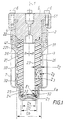
- the invention relates to a hydraulic capacity essentially comprising a hollow body 2, of elongated shape along an axis 1, and a rigid envelope 3 surrounding the hollow body 2.
- the wall 21 of the hollow body is, in the vicinity of the inlet-outlet orifice 22 of this last, provided with a groove 221 which is mounted on a rib 41 formed at the internal periphery of a retaining ring 4.
- the ring 4 is itself interposed between the rigid casing 3 and a fitting hydraulic 5 which opens into the orifice 22 of the hollow body, this connection being fixed to the rigid casing 3 by means of screws 6, and the ring 4 being immobilized along axis 1 by pressing on respective shoulders 31, 51 of the envelope and the fitting.
- a cover 7 may possibly be provided on the rigid envelope 3 for the protect from environmental pollution.
- the hollow body 2 is made of an elastomeric material, for example rubber, to be able to undergo elastic expansion without damage according to a radial direction R, and possibly also in the direction of axis 1, from a state of rest which is that illustrated in FIG. 1, the expansion of the hollow body 2 being blocked when the wall 21 is fully in contact with the rigid casing 3.
- an elastomeric material for example rubber
- the wall 21 of the hollow body 2 has, at rest, a thickness between a minimum thickness Ea and a maximum thickness Ez.
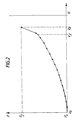
- the capacity thus constituted is intended to contain at all times a volume instantaneous V of fluid capable of evolving between a minimum volume Va and a maximum volume Vz (FIG. 2), the elastic wall 21 allowing, according to the present invention, to apply to the instantaneous volume V of fluid a pressure instantaneous P which depends on the instantaneous volume V according to a predetermined law, as shown in Figure 2.
- the wall 21 is simultaneously in contact with the casing 3 by at least first and second zones Z1, Z2 of this wall, and this at less for a given instantaneous volume of fluid, FIG. 1 representing in the occurrence the case where this volume is equal to Va and where the hollow body is in his state of rest.
- first and second zones Z1, Z2, which are distant from the orifice 22, have first and second respective thicknesses E1, E2, and are separated from each other by a third zone Z3, this third zone being itself distant from the envelope 3 and having a different third thickness E3 first and second thicknesses E1, E2.
- the hollow body 2 has an internal surface 23 essentially cylindrical at rest, the wall 21 reaching its thickness minimum Ea at one end 24 of the hollow body 2, opposite the orifice 22, and having at this end 24 an external surface 25 inscribed, at rest, in a cylinder of first diameter D1.
- the wall 21, in the example illustrated, reaches its maximum thickness Ez by a plurality of intermediate zones 26 located axially between the orifice 22 and the end 24 of the hollow body 2, and in which the wall 21 has a external surface inscribed, at rest, in a cylinder of third diameter D3, greater than the second diameter D2.
- openings 32 can be made in the envelope rigid 3 to allow the escape of air trapped between the hollow body 2 and this envelope 3.
- the resistance of the hollow body to its expansion expressed in terms of increase in instantaneous pressure P for an increase given of the instantaneous volume V, is an increasing function of the thickness of the wall 21 in the zone where this hollow body undergoes its expansion, and a decreasing function of the area of the area undergoing expansion.
- any increase in this volume therefore causes the radial and axial expansion of the end 24 of the hollow body 2, the thickness of which is minimal, and the resistance of the hollow body to its expansion is relatively small.
- the pressure P varies more quickly for the same increase in volume that for volumes lower than Vy, this variation depending on the distribution thickness zones such as E2, E3, Ez, in accordance with previously stated principles.
Landscapes
- Engineering & Computer Science (AREA)
- Physics & Mathematics (AREA)
- Fluid Mechanics (AREA)
- Mechanical Engineering (AREA)
- Transportation (AREA)
- General Engineering & Computer Science (AREA)
- Supply Devices, Intensifiers, Converters, And Telemotors (AREA)
- Braking Systems And Boosters (AREA)
- Valves And Accessory Devices For Braking Systems (AREA)
- Regulating Braking Force (AREA)
- Pipe Accessories (AREA)
- Actuator (AREA)
Applications Claiming Priority (3)
| Application Number | Priority Date | Filing Date | Title |
|---|---|---|---|
| FR9808101 | 1998-06-26 | ||
| FR9808101A FR2780369B1 (fr) | 1998-06-26 | 1998-06-26 | Capacite hydraulique a absorption controlee en pression |
| PCT/FR1999/001344 WO2000000373A1 (fr) | 1998-06-26 | 1999-06-08 | Capacite hydraulique a absorption controlee en pression |
Publications (2)
| Publication Number | Publication Date |
|---|---|
| EP1089903A1 EP1089903A1 (fr) | 2001-04-11 |
| EP1089903B1 true EP1089903B1 (fr) | 2002-09-18 |
Family
ID=9527882
Family Applications (1)
| Application Number | Title | Priority Date | Filing Date |
|---|---|---|---|
| EP99923689A Expired - Lifetime EP1089903B1 (fr) | 1998-06-26 | 1999-06-08 | Capacite hydraulique a absorption controlee en pression |
Country Status (8)
| Country | Link |
|---|---|
| US (1) | US6164336A (enExample) |
| EP (1) | EP1089903B1 (enExample) |
| JP (1) | JP4597372B2 (enExample) |
| KR (1) | KR100585611B1 (enExample) |
| DE (1) | DE69903033T2 (enExample) |
| ES (1) | ES2182525T3 (enExample) |
| FR (1) | FR2780369B1 (enExample) |
| WO (1) | WO2000000373A1 (enExample) |
Families Citing this family (25)
| Publication number | Priority date | Publication date | Assignee | Title |
|---|---|---|---|---|
| US5941608A (en) | 1996-03-07 | 1999-08-24 | Kelsey-Hayes Company | Electronic brake management system with manual fail safe |
| DE19856697C2 (de) * | 1998-12-09 | 2001-02-22 | Zahnradfabrik Friedrichshafen | Schwingungsdämpfer zur Dämpfung von Flüssigkeits-Schwingungen in einem hydraulischen System |
| FR2829452B1 (fr) * | 2001-09-10 | 2005-01-28 | Bosch Gmbh Robert | Installation de freinage hydraulique avec simulateur, et simulateur pour une telle installation |
| FR2829982B1 (fr) * | 2001-09-26 | 2004-01-23 | Bosch Gmbh Robert | Dispositif de freinage a securite accrue et systeme de freinage comportant un tel dispositif |
| US7040350B2 (en) * | 2002-04-23 | 2006-05-09 | Young Winston B | Perforated pulsation dampener and dampening system |
| US6860569B1 (en) | 2002-05-23 | 2005-03-01 | Kelsey-Hayes Company | Electro-hydraulic brake system with four wheel push through |
| US6651698B1 (en) * | 2002-05-31 | 2003-11-25 | Wilkes & Mclean Ltd. | Suppressor for manifold fluid line |
| US7493916B2 (en) * | 2005-12-12 | 2009-02-24 | Bosch Rexroth Corporation | Pressure vessel with accumulator isolation device |
| BR112012003088B1 (pt) * | 2009-08-24 | 2020-03-03 | Kelsey-Hayes Company | Sistema de frenagem de veículo |
| AU2010303729B2 (en) * | 2009-10-05 | 2014-02-13 | Robert Bosch Gmbh | Energy storage system including an expandable accumulator and reservoir assembly |
| DE102012221029A1 (de) * | 2012-11-19 | 2014-05-22 | Continental Teves Ag & Co. Ohg | Hydraulischer Simulator |
| DE102014224829A1 (de) * | 2014-12-04 | 2016-06-09 | Robert Bosch Gmbh | Druckänderungsdämpfer für eine schlupfgeregelte, hydraulische Fahrzeugbremsanlage und Fahrzeugbremsanlage mit einem solchen Druckänderungsdämpfer |
| DE102014226005A1 (de) * | 2014-12-16 | 2016-06-16 | Robert Bosch Gmbh | Druckänderungsdämpfer für eine bremskraftgeregelte hydraulische Fahrzeugbremsanlage und bremskraftgeregelte hydraulische Fahrzeugbremsanlage mit einem solchen Druckänderungsdämpfer |
| KR101698881B1 (ko) * | 2015-09-02 | 2017-01-23 | 주식회사 만도 | 유압 브레이크 시스템의 맥동 저감 장치 |
| KR102508991B1 (ko) * | 2016-01-29 | 2023-03-10 | 에이치엘만도 주식회사 | 브레이크 시스템 |
| DE102016201737A1 (de) * | 2016-02-04 | 2017-08-10 | Continental Teves Ag & Co. Ohg | Simulatoreinrichtung für eine Bremsanlage und Bremsanlage |
| FR3060533B1 (fr) * | 2016-12-19 | 2025-04-11 | Safran Aircraft Engines | Accumulateur sur une ligne de carburant d'aeronef |
| US10926747B2 (en) * | 2018-03-14 | 2021-02-23 | Mando Corporation | Pulsation damping device of hydraulic brake system |
| US11125374B2 (en) * | 2018-06-25 | 2021-09-21 | Performance Pulsation Control, Inc. | Retaining sleeve for high pre-charge cartridge |
| DE102018219605A1 (de) * | 2018-07-07 | 2020-01-09 | Robert Bosch Gmbh | Bremssystemdämpfvorrichtung |
| DE102019208406A1 (de) * | 2019-06-08 | 2020-12-10 | Robert Bosch Gmbh | Bremssystemdämpfvorrichtung |
| DE102019210649A1 (de) * | 2019-07-18 | 2021-01-21 | Robert Bosch Gmbh | Bremssystemdämpfvorrichtung mit einem Durchlass |
| DE102019215988A1 (de) * | 2019-10-17 | 2021-04-22 | Continental Teves Ag & Co. Ohg | Pulsationsdämpfer |
| AU2021211391A1 (en) * | 2020-01-21 | 2023-01-05 | UGT Group Pty Ltd | Accumulator |
| US11866023B2 (en) | 2021-04-19 | 2024-01-09 | Bwi (Shanghai) Co., Ltd. | Noise mitigating hydraulic control unit assembly for a vehicle braking system |
Family Cites Families (10)
| Publication number | Priority date | Publication date | Assignee | Title |
|---|---|---|---|---|
| US1950107A (en) * | 1932-07-30 | 1934-03-06 | Welford P Guinn | Pressure alleviator |
| NL121651C (enExample) * | 1960-06-29 | |||
| JPS5843498Y2 (ja) * | 1979-04-03 | 1983-10-01 | 株式会社豊田自動織機製作所 | ト−シヨンバ−を利用した蓄圧装置 |
| US4687188A (en) * | 1986-02-04 | 1987-08-18 | Cooper Tire & Rubber Company | Mount for controlling or isolating vibration |
| JPH0752401Y2 (ja) * | 1990-01-29 | 1995-11-29 | 東海ゴム工業株式会社 | ブラダ型アキュムレータ |
| JPH07237534A (ja) * | 1994-02-28 | 1995-09-12 | Toyota Motor Corp | 車両用ブレーキ液圧制御装置 |
| US5771936A (en) * | 1994-07-25 | 1998-06-30 | Nok Corporation | Accumulator, process and apparatus for making the same |
| DE19544221A1 (de) * | 1995-11-28 | 1997-06-05 | Bosch Gmbh Robert | Dämpfer, insbesondere zur Dämpfung von Druckschwankungen in Bremsflüssigkeit hydraulischer Fahrzeugbremsanlagen |
| US5682923A (en) * | 1996-09-30 | 1997-11-04 | Caterpillar Inc. | Accumulator having an internal elastomeric member |
| US6076557A (en) * | 1998-06-12 | 2000-06-20 | Senior Engineering Investments Ag | Thin wall, high pressure, volume compensator |
-
1998
- 1998-06-26 FR FR9808101A patent/FR2780369B1/fr not_active Expired - Fee Related
-
1999
- 1999-06-08 WO PCT/FR1999/001344 patent/WO2000000373A1/fr not_active Ceased
- 1999-06-08 DE DE69903033T patent/DE69903033T2/de not_active Expired - Lifetime
- 1999-06-08 KR KR1020007013997A patent/KR100585611B1/ko not_active Expired - Fee Related
- 1999-06-08 EP EP99923689A patent/EP1089903B1/fr not_active Expired - Lifetime
- 1999-06-08 JP JP2000556945A patent/JP4597372B2/ja not_active Expired - Fee Related
- 1999-06-08 ES ES99923689T patent/ES2182525T3/es not_active Expired - Lifetime
- 1999-06-08 US US09/331,944 patent/US6164336A/en not_active Expired - Lifetime
Also Published As
| Publication number | Publication date |
|---|---|
| FR2780369B1 (fr) | 2000-08-18 |
| DE69903033T2 (de) | 2003-04-30 |
| JP2002519233A (ja) | 2002-07-02 |
| JP4597372B2 (ja) | 2010-12-15 |
| DE69903033D1 (de) | 2002-10-24 |
| ES2182525T3 (es) | 2003-03-01 |
| US6164336A (en) | 2000-12-26 |
| KR100585611B1 (ko) | 2006-06-07 |
| KR20010078731A (ko) | 2001-08-21 |
| FR2780369A1 (fr) | 1999-12-31 |
| WO2000000373A1 (fr) | 2000-01-06 |
| EP1089903A1 (fr) | 2001-04-11 |
Similar Documents
| Publication | Publication Date | Title |
|---|---|---|
| EP1089903B1 (fr) | Capacite hydraulique a absorption controlee en pression | |
| EP0185389B1 (fr) | Amortisseur pour suspension de vehicule autombile | |
| EP0165088B1 (fr) | Frein à disque à étrier coulissant | |
| EP2440806B1 (fr) | Amortisseur et atterrisseur equipe d'un tel amortisseur | |
| EP0156666B1 (fr) | Correcteur de freinage perfectionné | |
| FR2812362A1 (fr) | Support antivibratoire hydraulique et son procede de fabrication | |
| FR2692624A1 (fr) | Piston pour moteurs à combustion interne. | |
| FR2935296A1 (fr) | Bande de roulement de pneu a sculpture directionnelle. | |
| EP0225227B2 (fr) | Perfectionnements aux supports antivibratiores hydrauliques | |
| EP0499526B1 (fr) | Système d'amortissement notamment pour systèmes d'arme | |
| CA2234434C (fr) | Procede de determination predictive en regime pre-critique de la charge a rupture d'une structure | |
| FR2491415A1 (fr) | Soupape de commande de pression de freinage, pour installations de freinage de vehicules automobiles, et procede de fabrication d'une telle soupape | |
| EP0533527A1 (fr) | Bloc hydropneumatique muni d'un accumulateur hydropneumatique à membrane et d'un amortisseur dissymétrique | |
| EP0939715B1 (fr) | Systeme de feinage assiste a reaction hydraulique amelioree | |
| EP0526275B1 (fr) | Correcteur de freinage perfectionné | |
| FR2479388A1 (fr) | Amortisseur hydraulique telescopique pour la suspension d'un vehicule automobile | |
| EP1057704B1 (fr) | Amplificateur de force de freinage perfectionné | |
| EP2015973B1 (fr) | Servofrein a rapport d'assistance variable | |
| EP1056633A1 (fr) | Servomoteur utilisant un filtre a densite controlee | |
| FR2705574A1 (fr) | Valve de drainage implantable pour le traitement de l'hydrocéphalie. | |
| EP0615501B1 (fr) | Direction assistee a compensation automatique de jeu | |
| FR2798344A1 (fr) | Servo pour frein automobile ou similaire | |
| WO2001063141A1 (fr) | Dispositif formant amortisseur dissymetrique pour une suspension de vehicule automobile | |
| FR2663781A1 (fr) | Contacteur electrique sensible a la pression a commutation brusque. | |
| EP0705748B1 (fr) | Servomoteur hydraulique d'assistance au freinage à caractéristique d'entrée modifiée |
Legal Events
| Date | Code | Title | Description |
|---|---|---|---|
| PUAI | Public reference made under article 153(3) epc to a published international application that has entered the european phase |
Free format text: ORIGINAL CODE: 0009012 |
|
| 17P | Request for examination filed |
Effective date: 20001104 |
|
| AK | Designated contracting states |
Kind code of ref document: A1 Designated state(s): DE ES FR GB IT |
|
| GRAG | Despatch of communication of intention to grant |
Free format text: ORIGINAL CODE: EPIDOS AGRA |
|
| 17Q | First examination report despatched |
Effective date: 20011119 |
|
| GRAG | Despatch of communication of intention to grant |
Free format text: ORIGINAL CODE: EPIDOS AGRA |
|
| GRAH | Despatch of communication of intention to grant a patent |
Free format text: ORIGINAL CODE: EPIDOS IGRA |
|
| GRAH | Despatch of communication of intention to grant a patent |
Free format text: ORIGINAL CODE: EPIDOS IGRA |
|
| GRAA | (expected) grant |
Free format text: ORIGINAL CODE: 0009210 |
|
| AK | Designated contracting states |
Kind code of ref document: B1 Designated state(s): DE ES FR GB IT |
|
| REG | Reference to a national code |
Ref country code: GB Ref legal event code: FG4D Free format text: NOT ENGLISH |
|
| GBT | Gb: translation of ep patent filed (gb section 77(6)(a)/1977) |
Effective date: 20020918 |
|
| REF | Corresponds to: |
Ref document number: 69903033 Country of ref document: DE Date of ref document: 20021024 |
|
| REG | Reference to a national code |
Ref country code: ES Ref legal event code: FG2A Ref document number: 2182525 Country of ref document: ES Kind code of ref document: T3 |
|
| PLBE | No opposition filed within time limit |
Free format text: ORIGINAL CODE: 0009261 |
|
| STAA | Information on the status of an ep patent application or granted ep patent |
Free format text: STATUS: NO OPPOSITION FILED WITHIN TIME LIMIT |
|
| 26N | No opposition filed |
Effective date: 20030619 |
|
| PGFP | Annual fee paid to national office [announced via postgrant information from national office to epo] |
Ref country code: FR Payment date: 20130703 Year of fee payment: 15 |
|
| PGFP | Annual fee paid to national office [announced via postgrant information from national office to epo] |
Ref country code: GB Payment date: 20140620 Year of fee payment: 16 |
|
| PGFP | Annual fee paid to national office [announced via postgrant information from national office to epo] |
Ref country code: ES Payment date: 20140618 Year of fee payment: 16 Ref country code: IT Payment date: 20140626 Year of fee payment: 16 |
|
| REG | Reference to a national code |
Ref country code: DE Ref legal event code: R084 Ref document number: 69903033 Country of ref document: DE |
|
| REG | Reference to a national code |
Ref country code: DE Ref legal event code: R084 Ref document number: 69903033 Country of ref document: DE Effective date: 20141231 |
|
| REG | Reference to a national code |
Ref country code: FR Ref legal event code: ST Effective date: 20150227 |
|
| PG25 | Lapsed in a contracting state [announced via postgrant information from national office to epo] |
Ref country code: FR Free format text: LAPSE BECAUSE OF NON-PAYMENT OF DUE FEES Effective date: 20140630 |
|
| PG25 | Lapsed in a contracting state [announced via postgrant information from national office to epo] |
Ref country code: IT Free format text: LAPSE BECAUSE OF NON-PAYMENT OF DUE FEES Effective date: 20150608 |
|
| GBPC | Gb: european patent ceased through non-payment of renewal fee |
Effective date: 20150608 |
|
| PG25 | Lapsed in a contracting state [announced via postgrant information from national office to epo] |
Ref country code: GB Free format text: LAPSE BECAUSE OF NON-PAYMENT OF DUE FEES Effective date: 20150608 |
|
| PGFP | Annual fee paid to national office [announced via postgrant information from national office to epo] |
Ref country code: DE Payment date: 20160810 Year of fee payment: 18 |
|
| REG | Reference to a national code |
Ref country code: ES Ref legal event code: FD2A Effective date: 20170203 |
|
| PG25 | Lapsed in a contracting state [announced via postgrant information from national office to epo] |
Ref country code: ES Free format text: LAPSE BECAUSE OF NON-PAYMENT OF DUE FEES Effective date: 20150609 |
|
| REG | Reference to a national code |
Ref country code: DE Ref legal event code: R119 Ref document number: 69903033 Country of ref document: DE |
|
| PG25 | Lapsed in a contracting state [announced via postgrant information from national office to epo] |
Ref country code: DE Free format text: LAPSE BECAUSE OF NON-PAYMENT OF DUE FEES Effective date: 20180103 |