EP1089777B1 - Gas outlet barrel retention apparatus - Google Patents
Gas outlet barrel retention apparatus Download PDFInfo
- Publication number
- EP1089777B1 EP1089777B1 EP99930497A EP99930497A EP1089777B1 EP 1089777 B1 EP1089777 B1 EP 1089777B1 EP 99930497 A EP99930497 A EP 99930497A EP 99930497 A EP99930497 A EP 99930497A EP 1089777 B1 EP1089777 B1 EP 1089777B1
- Authority
- EP
- European Patent Office
- Prior art keywords
- barrel
- back plate
- flange
- plate
- gas outlet
- Prior art date
- Legal status (The legal status is an assumption and is not a legal conclusion. Google has not performed a legal analysis and makes no representation as to the accuracy of the status listed.)
- Expired - Lifetime
Links
- 230000014759 maintenance of location Effects 0.000 title claims abstract description 21
- 230000008878 coupling Effects 0.000 claims description 4
- 238000010168 coupling process Methods 0.000 claims description 4
- 238000005859 coupling reaction Methods 0.000 claims description 4
- 238000003780 insertion Methods 0.000 claims description 4
- 230000037431 insertion Effects 0.000 claims description 4
- 238000009434 installation Methods 0.000 claims description 2
- 239000007789 gas Substances 0.000 description 31
- 239000000523 sample Substances 0.000 description 14
- 230000007246 mechanism Effects 0.000 description 11
- 238000007789 sealing Methods 0.000 description 4
- IJGRMHOSHXDMSA-UHFFFAOYSA-N Atomic nitrogen Chemical compound N#N IJGRMHOSHXDMSA-UHFFFAOYSA-N 0.000 description 2
- CURLTUGMZLYLDI-UHFFFAOYSA-N Carbon dioxide Chemical compound O=C=O CURLTUGMZLYLDI-UHFFFAOYSA-N 0.000 description 2
- GQPLMRYTRLFLPF-UHFFFAOYSA-N Nitrous Oxide Chemical compound [O-][N+]#N GQPLMRYTRLFLPF-UHFFFAOYSA-N 0.000 description 2
- 229910000831 Steel Inorganic materials 0.000 description 2
- 238000012423 maintenance Methods 0.000 description 2
- 239000010959 steel Substances 0.000 description 2
- RYGMFSIKBFXOCR-UHFFFAOYSA-N Copper Chemical compound [Cu] RYGMFSIKBFXOCR-UHFFFAOYSA-N 0.000 description 1
- 235000008331 Pinus X rigitaeda Nutrition 0.000 description 1
- 235000011613 Pinus brutia Nutrition 0.000 description 1
- 241000018646 Pinus brutia Species 0.000 description 1
- HCHKCACWOHOZIP-UHFFFAOYSA-N Zinc Chemical compound [Zn] HCHKCACWOHOZIP-UHFFFAOYSA-N 0.000 description 1
- 239000003570 air Substances 0.000 description 1
- QVGXLLKOCUKJST-UHFFFAOYSA-N atomic oxygen Chemical compound [O] QVGXLLKOCUKJST-UHFFFAOYSA-N 0.000 description 1
- 239000001569 carbon dioxide Substances 0.000 description 1
- 229910002092 carbon dioxide Inorganic materials 0.000 description 1
- 229910052802 copper Inorganic materials 0.000 description 1
- 239000010949 copper Substances 0.000 description 1
- 239000000428 dust Substances 0.000 description 1
- 239000002184 metal Substances 0.000 description 1
- 229910052751 metal Inorganic materials 0.000 description 1
- 229910052757 nitrogen Inorganic materials 0.000 description 1
- 239000001272 nitrous oxide Substances 0.000 description 1
- 239000001301 oxygen Substances 0.000 description 1
- 229910052760 oxygen Inorganic materials 0.000 description 1
- 125000006850 spacer group Chemical group 0.000 description 1
- 239000011701 zinc Substances 0.000 description 1
- 229910052725 zinc Inorganic materials 0.000 description 1
Images

Classifications
-
- F—MECHANICAL ENGINEERING; LIGHTING; HEATING; WEAPONS; BLASTING
- F16—ENGINEERING ELEMENTS AND UNITS; GENERAL MEASURES FOR PRODUCING AND MAINTAINING EFFECTIVE FUNCTIONING OF MACHINES OR INSTALLATIONS; THERMAL INSULATION IN GENERAL
- F16L—PIPES; JOINTS OR FITTINGS FOR PIPES; SUPPORTS FOR PIPES, CABLES OR PROTECTIVE TUBING; MEANS FOR THERMAL INSULATION IN GENERAL
- F16L37/00—Couplings of the quick-acting type
- F16L37/60—Couplings of the quick-acting type with plug and fixed wall housing
-
- Y—GENERAL TAGGING OF NEW TECHNOLOGICAL DEVELOPMENTS; GENERAL TAGGING OF CROSS-SECTIONAL TECHNOLOGIES SPANNING OVER SEVERAL SECTIONS OF THE IPC; TECHNICAL SUBJECTS COVERED BY FORMER USPC CROSS-REFERENCE ART COLLECTIONS [XRACs] AND DIGESTS
- Y10—TECHNICAL SUBJECTS COVERED BY FORMER USPC
- Y10T—TECHNICAL SUBJECTS COVERED BY FORMER US CLASSIFICATION
- Y10T137/00—Fluid handling
- Y10T137/598—With repair, tapping, assembly, or disassembly means
- Y10T137/6184—Removable valve with normally disabled supplemental check valve
- Y10T137/6188—Check valve disabled by normally movable main valve part
- Y10T137/6195—Spring bias
-
- Y—GENERAL TAGGING OF NEW TECHNOLOGICAL DEVELOPMENTS; GENERAL TAGGING OF CROSS-SECTIONAL TECHNOLOGIES SPANNING OVER SEVERAL SECTIONS OF THE IPC; TECHNICAL SUBJECTS COVERED BY FORMER USPC CROSS-REFERENCE ART COLLECTIONS [XRACs] AND DIGESTS
- Y10—TECHNICAL SUBJECTS COVERED BY FORMER USPC
- Y10T—TECHNICAL SUBJECTS COVERED BY FORMER US CLASSIFICATION
- Y10T137/00—Fluid handling
- Y10T137/6851—With casing, support, protector or static constructional installations
- Y10T137/6966—Static constructional installations
- Y10T137/6969—Buildings
- Y10T137/698—Wall
Definitions
- the present invention relates to a gas outlet for supplying a gas to a room. More particularly, the present invention relates to an improved gas outlet front body which facilitates maintenance or servicing of the gas outlet.
- gas outlet systems typically include a front body having a valve or barrel configured to be coupled to a back body assembly which is coupled to a gas supply line extending from a wall, headwall, or ceiling.
- valve or barrel of the front body must be removed and serviced to replace worn parts from time to time.
- O-ring seals within the barrel must be replaced in order to maintain acceptable sealing against gas flow.
- removal of the conventional barrels is difficult and requires removal of several parts. These loose parts may be dropped, lost or misplaced.
- U.S. -A-5236005 which is considered to represent the closest prior art, discloses a wall outlet comprising an index plate, a closure member connected to the index plate, and a connector valve for connection to a medical gas adaptor.
- the valve is connected to a backside of the index plate and is accessible from the front of the outlet when the closure member is removed.
- the present invention provides a gas outlet apparatus for a gas supply line, the apparatus comprising a front cover formed to include a gas outlet opening, a back plate coupled to the front cover, a gas outlet barrel having an inlet end, an outlet end, and a valve located between the inlet end and the outlet end, and retention means for securing the barrel to the back plate and the cover with the outlet end of the barrel in alignment with the gas outlet opening formed in the front cover, characterised in that the retention means comprises a retention portion located on the back plate, the retention portion being configured to engage the barrel adjacent the outlet end to secure the barrel to the back plate and the cover with the outlet end of the barrel in alignment with the gas outlet opening formed in the front cover when the retention portion and the barrel are in a first state and the retention portion being configured to not engage the barrel when the retention portion and the barrel are in a second state facilitating removal of the barrel from the back plate.
- the gas outlet of the present invention provides an improved latching or retention mechanism for coupling the barrel to the front body.
- the apparatus of the present invention permits quick detachment of the barrel from the front body for servicing, without removing fasteners or other parts from the front body which can then be lost or misplaced.
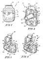
- FIG. 1 and 2 illustrate a front body 10 of a gas outlet system.
- Front body 10 includes a front cover 12 having a gas outlet opening 14 and spaced apart apertures 16 for receiving fasteners 18.
- a release button 20 is coupled to the front cover 12.
- a keying aperture 22 is also formed in the front cover 12. Keying aperture 22 mates with a projection 50 on a particular type of probe assembly 44, illustratively an Allied probe.
- a particular type of probe assembly 44 illustratively an Allied probe.
- another configuration of front body assembly is used for an outlet having a different type of keying system.
- the present invention is not limited to Allied keying. It is understood that the front body 10 may be keyed to receive any type of probe, including a Puritan-Bennett probe, a DISS barrel, etc.
- Fig. 2 illustrates a back plate 24 coupled to the front cover 12 by fasteners 26.
- the back plate 24 is formed to include an aperture 28 configured to receive an end 80 of a valve or barrel 30.
- a latch or retention mechanism 32 is provided to secure the barrel 30 to the back plate 24.
- Latch mechanism 32 illustratively includes a latch plate 34 and fastener 36 which is coupled to the back plate 24. Details of the latch mechanism 32 and coupling of barrel 30 to back plate 24 will be discussed below with reference to Figs. 6-10.
- the barrel 30 illustratively includes a primary piston 38, a secondary piston 40, and an O-ring seal 42.
- O-ring seal 42 on secondary piston 40 blocks gas flow through the barrel 30.
- Primary piston 38 serves as a dust plug and spacer to ensure that there is no gas flow through the barrel 30. unless a proper probe is inserted.
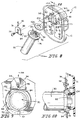
- Fig. 4 illustrates insertion of a probe 44 into aperture 14 of front body 12.
- Probe 44 includes a central projection 46 which enters aperture 14 and moves primary piston 38 in the direction of arrow 48 as shown in Fig. 4.
- Probe 44 also includes a keying projection 50 which enters keying aperture 22. As shown in Figs. 3 and 4, the keying projection 50 is locked in position by a plate 52. Downward movement of release button 20 causes downward movement of plate 52 to release the projection 50 of probe 44.
- the nose of probe projection 46 moves the primary piston 38 in the direction of arrow 48. Movement of the primary piston 38 causes movement of the secondary piston 40 and of the O-ring seal 42 away from a valve seat to permit gas to flow through the barrel 30 and into the probe projection 46.
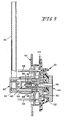
- Fig. 5 illustrates further details of the gas outlet assembly in which the front body 10 is coupled to a face plate 54. If the face plate 54 is plastic, then the face plate 54 is coupled to a steel backing plate 56 with suitable fasteners 58. If the face plate 54 is made from metal, such as zinc diecast, steel backing plate 56 is not required.
- a back body assembly 60 is coupled to the front body assembly 10 as shown.
- a gas supply line 62 is coupled to back body assembly 60.
- Back body assembly 60 includes a cylindrical pipe 64, a O-ring seal 66, and a bushing 68 which seals the pipe 64 of back body assembly 60 to the barrel 30 of front body assembly 10.
- the front body 10 can also be connected to a 1/4 National Pine Thread Male (NPTM) check unit, a Diameter Index Safety Standard (DISS) connection, a hose barb connection, copper tube connections, or any other desired connection.
- NPTM National Pine Thread Male
- DISS Diameter Index Safety Standard
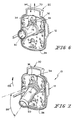
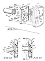
- the improved latch mechanism 34 for the barrel 30 is best illustrated in Figs. 6-10. As discussed above, it is understood that the latch mechanism 34 may be used with any desired type of gas outlet and is not limited to the particular configuration of the front body 10.
- the fastener 36 When it is desired to remove the barrel 30 for servicing, the fastener 36 is loosened so that the latch plate 34 can slide upwardly in the direction of arrow 70 in Fig. 6.
- the barrel 30 includes an annular ring 72 and a flange 74 having a larger diameter than the annular ring 72 adjacent an end 80 of barrel 30.
- An annular ring 76 is also formed on end 80 of barrel 30 as shown in Fig. 8.
- An O-ring seal 82 is located within annular ring 76 surrounding primary piston 38.
- Latch plate 34 is formed to include an inwardly projecting edge 84 configured to engage flange 74 of barrel 30 to retain the barrel 30 within the front body 10.
- the latch plate 34 includes an elongated slot 88.
- Fastener 36 extends through the elongated slot 88 into a threaded aperture 90 formed in back plate 24. It is understood that a threaded aperture for receiving fastener 36 may also be formed in cover 12 if desired.
- Elongated slot 88 permits the latch plate 34 to move up and down in the direction of double-headed arrow 92 of Fig. 8 without removal of the fastener 36. Therefore, the fastener 36 and latch plate 34 remain coupled to the front body 10 during removal of the barrel 30 to reduce the likelihood that the parts will be lost or misplaced.
- a spring biased member may be used to hold the barrel 30 downwardly into the locked position of Fig. 10.
- Such spring biased member may be used with or without a separate fastener for securing the barrel 30 to the front body 10.
- Other types of sliding coupling mechanisms may also be used.
- a bayonet-type connection of barrel 30 may be used.
- the barrel 30 has a nonsymmetrical flange which is inserted into a nonsymmetrical opening formed in back plate 24 and then rotated so that flanges on the barrel cannot be removed from back plate 24 without rotating the barrel 30 as discussed below with reference to Figs. 11-17.
- Figs. 9 and 10 illustrate that inwardly projecting edge 84 of latch plate 34 overlaps and engages flange 74 of barrel 30 when latch plate 34 is moved downwardly in the direction of arrow 94. Once the latch plate 34 engages the flange 74, fastener 36 is tightened to secure the barrel 30 in the locked position.
- Plate 24 is formed to include an aperture 28 for receiving end 80 of barrel 30.
- the aperture includes outer side portions 98 which have a diameter substantially equal to a diameter of flange 74.
- a lip portion 100 is configured to engage a bottom portion of flange 74 to hold the barrel 30 on the front body 10 as best illustrated in Figs. 9 and 10. In other words, the flange 74 is locked behind the plate 24 by lip 100.
- Lip 100 includes a curved notch 101 configured to engage annular ring 72.
- Top surface 102 of aperture 96 provides room for inwardly projecting edge 84 of latch plate 34 to move.
- Figs. 8 and 10 illustrate a washer 104 configured to be inserted into the front body 10 prior to barrel 30. Washer 104 provides a sealing surface for O-ring 82 as best illustrated in Fig. 10. It is understood that the cover 12 may be formed to include an appropriate sealing surface so that washer 104 is not required.
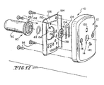
- Front body 12 includes a gas outlet 14 and keying apertures 120 and 122 formed in front cover 12.
- a back plate 124 includes a rear panel 126 and side walls 128 and 130. Back plate 124 is configured to be coupled to front cover 12 by fasteners 26.
- Rear panel 126 of back plate 24 is formed to include a central aperture 132 configured to receive the outlet end 80 of barrel 30.
- a washer 104 and U-shaped spring clip are located in the front body 10.
- An O-ring 82 is provided for sealing the barrel 30 as discussed above.
- the flange 74 of barrel 30 is formed to include a flat surface 133 so that flange 174 is non-symmetrical.
- Aperture 132 is defined in part by first and second side walls 134 and 136 which are generally arcuate to match the curve of the outer flange 74.
- Aperture 132 is further defined by a bottom flat wall 138 and a top flat wall 140. Side walls 134, 136 and top flat wall 140 cooperate to define an opening size to receive the flat portion 133 and adjacent curved sections of the flange 74.
- Figs. 12-16 Installation of the barrel 30 into the back plate 124 is illustrated in the Figs. 12-16.
- the curved portion of flange 74 is aligned at an angle and positioned behind bottom flat wall 138 as shown in Fig. 12.
- the flat surface 133 is aligned with the flat side wall 140 and the barrel 30 is rotated upwardly in the direction of arrow 142 of Fig. 12 to the position shown in Figs. 13 and 14.
- the entire flange 74 of barrel 30 is located between back plate 124 and front cover 12.
- top flat portion 133 of flange 74 rotates to the position shown in Figs. 15 and 16 to lock the barrel 30 to the back plate 24.
- a curved portion of flange 74 rotates upwardly behind the top wall 140 formed in back plate 124 to secure the barrel 30 to the front body 10.
- Barrel 30 can be easily removed from the front body 10 for servicing by rotating the barrel in the direction of barrel 146 or continuing rotation of the barrel 30 in the direction of arrow 144 or until the flat 133 on flange 74 is again aligned with the flat wall 140 formed in back plate 124. The barrel 30 can then be pivoted downwardly to a position of Fig. 12 and removed from the front body 10.
- the back plate 124 is formed to include a top tab portion 150 spaced apart from bottom flat wall 138.
- Flange 74 of barrel 30 is formed to include a slot 152 sized slightly larger than tab 150. Therefore, the barrel 30 is installed onto the back plate 124 in a manner similar to the manner described above. The barrel is first aligned with an angle and a portion of the flange 74 is hooked over the bottom flat wall 138. The barrel 30 is then pivoted upwardly with the slot 152 aligned with tab 150 so that the slot 152 passes over the tab 150.
- the barrel 30 is rotated so that the tab 150 engages a portion of the flange 74 to retain the barrel 30 within the front body 10.
- Barrel 30 can be easily removed from the front body 10 for servicing by rotating the barrel 30 until the slot 152 formed in the flange 74 is aligned with the tab 150 formed in back plate 124.
- the barrel 30 can then be pivoted downwardly to a position of Fig. 12 and removed from the front body 10.
- the barrel 30 can therefore be removed from front body assembly 10 without removal of parts from the front body assembly 10. This reduces the likelihood that parts will be lost or misplaced during servicing or maintenance of the barrel 30.
Landscapes
- Engineering & Computer Science (AREA)
- General Engineering & Computer Science (AREA)
- Mechanical Engineering (AREA)
- Quick-Acting Or Multi-Walled Pipe Joints (AREA)
- Surgical Instruments (AREA)
- Sampling And Sample Adjustment (AREA)
- Exhaust Gas After Treatment (AREA)
- Exhaust-Gas Circulating Devices (AREA)
- Infusion, Injection, And Reservoir Apparatuses (AREA)
- External Artificial Organs (AREA)
Applications Claiming Priority (3)
| Application Number | Priority Date | Filing Date | Title |
|---|---|---|---|
| US9055398P | 1998-06-24 | 1998-06-24 | |
| US90553P | 1998-06-24 | ||
| PCT/US1999/013973 WO1999066968A2 (en) | 1998-06-24 | 1999-06-21 | Gas outlet barrel retention apparatus |
Publications (3)
| Publication Number | Publication Date |
|---|---|
| EP1089777A2 EP1089777A2 (en) | 2001-04-11 |
| EP1089777A4 EP1089777A4 (en) | 2004-05-19 |
| EP1089777B1 true EP1089777B1 (en) | 2007-02-21 |
Family
ID=22223291
Family Applications (1)
| Application Number | Title | Priority Date | Filing Date |
|---|---|---|---|
| EP99930497A Expired - Lifetime EP1089777B1 (en) | 1998-06-24 | 1999-06-21 | Gas outlet barrel retention apparatus |
Country Status (8)
| Country | Link |
|---|---|
| US (1) | US6347643B1 (enExample) |
| EP (1) | EP1089777B1 (enExample) |
| JP (1) | JP4492835B2 (enExample) |
| AT (1) | ATE354760T1 (enExample) |
| AU (1) | AU4702999A (enExample) |
| CA (1) | CA2334685C (enExample) |
| DE (1) | DE69935222T2 (enExample) |
| WO (1) | WO1999066968A2 (enExample) |
Families Citing this family (4)
| Publication number | Priority date | Publication date | Assignee | Title |
|---|---|---|---|---|
| US6405491B1 (en) | 1999-04-22 | 2002-06-18 | Hill-Rom Services, Inc. | Modular patient room |
| US6581593B1 (en) * | 2001-04-03 | 2003-06-24 | Darren A. Rubin | Universal oxygen connector system |
| US7857354B2 (en) * | 2006-05-19 | 2010-12-28 | Lifespan Healthcare, Llc, A Florida Limited Liability Company | Component-based utility supply apparatus |
| US10512747B2 (en) * | 2016-09-22 | 2019-12-24 | Amico Interiors Corporation | Gas outlet extender |
Family Cites Families (38)
| Publication number | Priority date | Publication date | Assignee | Title |
|---|---|---|---|---|
| US3003213A (en) | 1955-02-17 | 1961-10-10 | Stile Craft Mfg Inc | Latching device |
| US2905487A (en) | 1956-07-20 | 1959-09-22 | Herbert E Schifter | Double valve construction and the like |
| US3036814A (en) * | 1959-12-24 | 1962-05-29 | Filtex Corp | Inlet valve assembly |
| US3287031A (en) | 1964-09-21 | 1966-11-22 | William H Simmons | Indexed keyed connection |
| US3448760A (en) | 1966-06-08 | 1969-06-10 | Stile Craft Mfg Inc | Coupler assembly |
| US3565103A (en) * | 1968-07-31 | 1971-02-23 | Spencer Turbine Co The | Socket and valve for central vacuum system |
| US3563267A (en) | 1968-09-30 | 1971-02-16 | Air Reduction | Gas dispensing double check valve construction |
| US3643985A (en) | 1969-12-04 | 1972-02-22 | Stile Craft Mfg Inc | Latching device for coupling assembly |
| US3661356A (en) * | 1970-02-09 | 1972-05-09 | Natter Mfg Corp | Inlet valve assembly for pneumatic system |
| GB1330403A (en) | 1971-03-17 | 1973-09-19 | Crosweller & Co Ltd W | Fluid flow systems |
| US3931829A (en) | 1973-06-29 | 1976-01-13 | Oxequip Health Industries | Valved service outlet |
| US4150673A (en) | 1977-02-03 | 1979-04-24 | Pharmachem Corporation | Coded entry system for blood bag |
| US4190075A (en) | 1977-09-26 | 1980-02-26 | Airco, Inc. | Double valve construction |
| FR2406869A1 (fr) | 1977-10-21 | 1979-05-18 | Framatome Sa | Dispositif de protection des tuyauteries de vapeur a la sortie d'un reacteur nucleaire |
| US4344455A (en) | 1980-08-18 | 1982-08-17 | Tuthill Corporation | Coupling assembly |
| US4354523A (en) | 1980-11-19 | 1982-10-19 | Acf Industries, Incorporated | Lubricant fitting for a valve |
| US4509554A (en) | 1982-11-08 | 1985-04-09 | Failla William G | High and low pressure, quick-disconnect coupling |
| US4718699A (en) | 1983-02-14 | 1988-01-12 | Allied Healthcare Products, Inc. | Gas system outlet station assembly |
| US4527587A (en) | 1983-03-28 | 1985-07-09 | Union Carbide Canada Limited | Connector assembly for a gas |
| DE3327829A1 (de) | 1983-08-02 | 1985-02-14 | Hansa Metallwerke Ag, 7000 Stuttgart | Sanitaere unterputzarmatur |
| GB2160561B (en) | 1984-06-20 | 1987-07-29 | Nippon Speed Shore | An expansion beam for shoring sand guards |
| US4562856A (en) | 1984-10-01 | 1986-01-07 | Union Carbide Canada Limited | Connector assembly for a gas |
| FR2576385B1 (fr) | 1985-01-18 | 1987-07-17 | Duffour & Igon Sa | Prise de distribution de fluides, en particulier pour etablissements hospitaliers |
| EP0217055B1 (en) | 1985-07-31 | 1991-01-09 | Kawasumi Laboratories, Inc. | A connector for plasmapheresis bag |
| US4617012A (en) | 1985-10-29 | 1986-10-14 | Manresa, Inc. | Sterile connector with movable connection member |
| US5353837A (en) | 1986-03-04 | 1994-10-11 | Deka Products Limited Partnership | Quick-disconnect valve |
| US4774939A (en) | 1987-07-02 | 1988-10-04 | Disney Alfred L | Emergency breathing and warning device |
| US4844409A (en) | 1988-10-24 | 1989-07-04 | The Boc Group, Inc. | Medical gas adapter with molded spring bias |
| US4915132A (en) | 1989-01-23 | 1990-04-10 | The Boc Group, Inc. | Gas regulator selector valve |
| US5129423A (en) | 1990-03-16 | 1992-07-14 | Aeroquip Corporation | No-spill fluid security coupling |
| IT1249173B (it) | 1991-04-03 | 1995-02-18 | Fk Arna S R L | Dispositivo valvolare per il prelievo di aria compressa da un serbatoio fisso da parte di un'unita' mobile |
| AU1812392A (en) | 1991-07-12 | 1993-01-14 | Minnesota Mining And Manufacturing Company | Bottle keying system |
| US5131429A (en) | 1991-08-15 | 1992-07-21 | Janis Research Company, Inc. | Fluid injector assembly |
| US5197511A (en) | 1992-01-30 | 1993-03-30 | Allied Healthcare Products, Inc. | Fluid outlet system |
| US5236005A (en) * | 1992-08-31 | 1993-08-17 | Tri-Tech Medical, Inc. | Quick connect wall outlet for medical gas service outlet |
| DE4241989A1 (de) | 1992-12-12 | 1994-06-16 | Grohe Armaturen Friedrich | Unterputz-Armatur |
| FR2700597B1 (fr) | 1993-01-20 | 1995-02-24 | Snecma | Clapet de distribution de fluide. |
| US5562121A (en) | 1995-04-06 | 1996-10-08 | Allied Healthcare Products, Inc. | Gas delivery system with universal outlet |
-
1999
- 1999-06-21 EP EP99930497A patent/EP1089777B1/en not_active Expired - Lifetime
- 1999-06-21 AT AT99930497T patent/ATE354760T1/de not_active IP Right Cessation
- 1999-06-21 CA CA002334685A patent/CA2334685C/en not_active Expired - Fee Related
- 1999-06-21 WO PCT/US1999/013973 patent/WO1999066968A2/en not_active Ceased
- 1999-06-21 US US09/701,621 patent/US6347643B1/en not_active Expired - Lifetime
- 1999-06-21 JP JP2000555654A patent/JP4492835B2/ja not_active Expired - Fee Related
- 1999-06-21 DE DE69935222T patent/DE69935222T2/de not_active Expired - Lifetime
- 1999-06-21 AU AU47029/99A patent/AU4702999A/en not_active Abandoned
Also Published As
| Publication number | Publication date |
|---|---|
| EP1089777A4 (en) | 2004-05-19 |
| DE69935222D1 (de) | 2007-04-05 |
| CA2334685A1 (en) | 1999-12-29 |
| US6347643B1 (en) | 2002-02-19 |
| EP1089777A2 (en) | 2001-04-11 |
| DE69935222T2 (de) | 2007-10-25 |
| CA2334685C (en) | 2008-09-02 |
| WO1999066968A3 (en) | 2000-06-15 |
| WO1999066968A2 (en) | 1999-12-29 |
| JP2002518654A (ja) | 2002-06-25 |
| AU4702999A (en) | 2000-01-10 |
| ATE354760T1 (de) | 2007-03-15 |
| JP4492835B2 (ja) | 2010-06-30 |
Similar Documents
| Publication | Publication Date | Title |
|---|---|---|
| US10995781B2 (en) | Filter clamp lock | |
| US5562121A (en) | Gas delivery system with universal outlet | |
| US6447027B1 (en) | Quick connect hydrant nozzle for connecting a fire hose to a fire hydrant | |
| US20040134534A1 (en) | Horizontal-flow trap and housing assembly with odor preventing closure mechanism | |
| US20120326439A1 (en) | Valve and Other Connections | |
| EP0682757B1 (en) | Quick connector | |
| US20090230671A1 (en) | Jet diffusor comprising a withdrawl mechanism | |
| EP1089777B1 (en) | Gas outlet barrel retention apparatus | |
| US20070062603A1 (en) | Refueling assembly having a check valve receptacle and a replaceable fuel receiver for bottom-filled fuel tanks | |
| US5263470A (en) | Method and apparatus for use in installing a firebox in a fireplace in connection with a flue liner | |
| US6168209B1 (en) | Keyed cap for gas outlet valve | |
| US11692633B2 (en) | Pinch clamp and mount | |
| EP1017951B1 (en) | Keyed cap for gas outlet valve | |
| US20060175835A1 (en) | Union nut with lock member | |
| WO2009047554A1 (en) | Cap for a fluid coupling member | |
| CA2245800A1 (en) | Lockable coupling | |
| US20200369255A1 (en) | Angle cock that does not require tools for repair | |
| US20200292111A1 (en) | Plug-In Connection System for Fluid-Conducting Components, in Particular of Fire-Extinguishing Systems, and Component Parts of Said Connection System | |
| CN220233113U (zh) | 半导体工艺设备 | |
| GB2110787A (en) | Closure means for pipe fittings | |
| JP2005163950A (ja) | 管継手 |
Legal Events
| Date | Code | Title | Description |
|---|---|---|---|
| PUAI | Public reference made under article 153(3) epc to a published international application that has entered the european phase |
Free format text: ORIGINAL CODE: 0009012 |
|
| 17P | Request for examination filed |
Effective date: 20001221 |
|
| AK | Designated contracting states |
Kind code of ref document: A2 Designated state(s): AT BE CH DE FR GB IT LI LU NL |
|
| RIC1 | Information provided on ipc code assigned before grant |
Free format text: 7F 16L 5/00 A |
|
| RAP1 | Party data changed (applicant data changed or rights of an application transferred) |
Owner name: MEDAES, INC. |
|
| A4 | Supplementary search report drawn up and despatched |
Effective date: 20040402 |
|
| RIC1 | Information provided on ipc code assigned before grant |
Ipc: 7F 16L 37/00 B Ipc: 7F 16L 37/60 B Ipc: 7F 16L 5/00 A |
|
| RAP1 | Party data changed (applicant data changed or rights of an application transferred) |
Owner name: BEACON MEDICAL PRODUCTS LLC. |
|
| 17Q | First examination report despatched |
Effective date: 20050427 |
|
| GRAP | Despatch of communication of intention to grant a patent |
Free format text: ORIGINAL CODE: EPIDOSNIGR1 |
|
| GRAS | Grant fee paid |
Free format text: ORIGINAL CODE: EPIDOSNIGR3 |
|
| GRAA | (expected) grant |
Free format text: ORIGINAL CODE: 0009210 |
|
| AK | Designated contracting states |
Kind code of ref document: B1 Designated state(s): AT BE CH DE FR GB IT LI LU NL |
|
| PG25 | Lapsed in a contracting state [announced via postgrant information from national office to epo] |
Ref country code: NL Free format text: LAPSE BECAUSE OF FAILURE TO SUBMIT A TRANSLATION OF THE DESCRIPTION OR TO PAY THE FEE WITHIN THE PRESCRIBED TIME-LIMIT Effective date: 20070221 Ref country code: LI Free format text: LAPSE BECAUSE OF FAILURE TO SUBMIT A TRANSLATION OF THE DESCRIPTION OR TO PAY THE FEE WITHIN THE PRESCRIBED TIME-LIMIT Effective date: 20070221 Ref country code: CH Free format text: LAPSE BECAUSE OF FAILURE TO SUBMIT A TRANSLATION OF THE DESCRIPTION OR TO PAY THE FEE WITHIN THE PRESCRIBED TIME-LIMIT Effective date: 20070221 Ref country code: AT Free format text: LAPSE BECAUSE OF FAILURE TO SUBMIT A TRANSLATION OF THE DESCRIPTION OR TO PAY THE FEE WITHIN THE PRESCRIBED TIME-LIMIT Effective date: 20070221 |
|
| REG | Reference to a national code |
Ref country code: GB Ref legal event code: FG4D |
|
| REG | Reference to a national code |
Ref country code: CH Ref legal event code: EP |
|
| REF | Corresponds to: |
Ref document number: 69935222 Country of ref document: DE Date of ref document: 20070405 Kind code of ref document: P |
|
| NLV1 | Nl: lapsed or annulled due to failure to fulfill the requirements of art. 29p and 29m of the patents act | ||
| ET | Fr: translation filed | ||
| REG | Reference to a national code |
Ref country code: CH Ref legal event code: PL |
|
| PLBE | No opposition filed within time limit |
Free format text: ORIGINAL CODE: 0009261 |
|
| STAA | Information on the status of an ep patent application or granted ep patent |
Free format text: STATUS: NO OPPOSITION FILED WITHIN TIME LIMIT |
|
| 26N | No opposition filed |
Effective date: 20071122 |
|
| PG25 | Lapsed in a contracting state [announced via postgrant information from national office to epo] |
Ref country code: LU Free format text: LAPSE BECAUSE OF NON-PAYMENT OF DUE FEES Effective date: 20070621 |
|
| REG | Reference to a national code |
Ref country code: DE Ref legal event code: R082 Ref document number: 69935222 Country of ref document: DE Representative=s name: WABLAT, WOLFGANG, DIPL.-CHEM. DR.-ING. DR.JUR., DE |
|
| REG | Reference to a national code |
Ref country code: DE Ref legal event code: R082 Ref document number: 69935222 Country of ref document: DE Representative=s name: WABLAT, WOLFGANG, DIPL.-CHEM. DR.-ING. DR.JUR., DE Effective date: 20140211 Ref country code: DE Ref legal event code: R081 Ref document number: 69935222 Country of ref document: DE Owner name: BEACONMEDAES LLC (N.D.GES.D. STAATES DELAWARE), US Free format text: FORMER OWNER: BEACON MEDICAL PRODUCTS LLC., CHARLOTTE, N.C., US Effective date: 20140211 Ref country code: DE Ref legal event code: R081 Ref document number: 69935222 Country of ref document: DE Owner name: BEACONMEDAES LLC (N.D.GES.D. STAATES DELAWARE), US Free format text: FORMER OWNER: BEACON MEDICAL PRODUCTS LLC., CHARLOTTE, US Effective date: 20140211 |
|
| REG | Reference to a national code |
Ref country code: FR Ref legal event code: CD Owner name: BEACONMEDAES LLC., US Effective date: 20140806 Ref country code: FR Ref legal event code: CA Effective date: 20140806 |
|
| REG | Reference to a national code |
Ref country code: FR Ref legal event code: PLFP Year of fee payment: 18 |
|
| PGFP | Annual fee paid to national office [announced via postgrant information from national office to epo] |
Ref country code: FR Payment date: 20160628 Year of fee payment: 18 Ref country code: BE Payment date: 20160627 Year of fee payment: 18 |
|
| PGFP | Annual fee paid to national office [announced via postgrant information from national office to epo] |
Ref country code: IT Payment date: 20160627 Year of fee payment: 18 Ref country code: DE Payment date: 20160628 Year of fee payment: 18 |
|
| REG | Reference to a national code |
Ref country code: DE Ref legal event code: R119 Ref document number: 69935222 Country of ref document: DE |
|
| REG | Reference to a national code |
Ref country code: FR Ref legal event code: ST Effective date: 20180228 |
|
| PG25 | Lapsed in a contracting state [announced via postgrant information from national office to epo] |
Ref country code: DE Free format text: LAPSE BECAUSE OF NON-PAYMENT OF DUE FEES Effective date: 20180103 |
|
| PG25 | Lapsed in a contracting state [announced via postgrant information from national office to epo] |
Ref country code: FR Free format text: LAPSE BECAUSE OF NON-PAYMENT OF DUE FEES Effective date: 20170630 Ref country code: IT Free format text: LAPSE BECAUSE OF NON-PAYMENT OF DUE FEES Effective date: 20170621 |
|
| REG | Reference to a national code |
Ref country code: BE Ref legal event code: MM Effective date: 20170630 |
|
| PG25 | Lapsed in a contracting state [announced via postgrant information from national office to epo] |
Ref country code: BE Free format text: LAPSE BECAUSE OF NON-PAYMENT OF DUE FEES Effective date: 20170630 |
|
| PGFP | Annual fee paid to national office [announced via postgrant information from national office to epo] |
Ref country code: GB Payment date: 20180627 Year of fee payment: 20 |
|
| REG | Reference to a national code |
Ref country code: GB Ref legal event code: PE20 Expiry date: 20190620 |
|
| PG25 | Lapsed in a contracting state [announced via postgrant information from national office to epo] |
Ref country code: GB Free format text: LAPSE BECAUSE OF EXPIRATION OF PROTECTION Effective date: 20190620 |