EP1089666B1 - Appareil de distribution a deux voies d'un liquide sterile de travail pour des applications medicales - Google Patents
Appareil de distribution a deux voies d'un liquide sterile de travail pour des applications medicales Download PDFInfo
- Publication number
- EP1089666B1 EP1089666B1 EP99957140A EP99957140A EP1089666B1 EP 1089666 B1 EP1089666 B1 EP 1089666B1 EP 99957140 A EP99957140 A EP 99957140A EP 99957140 A EP99957140 A EP 99957140A EP 1089666 B1 EP1089666 B1 EP 1089666B1
- Authority
- EP
- European Patent Office
- Prior art keywords
- generating apparatus
- liquid
- depression
- pressurized
- flow
- Prior art date
- Legal status (The legal status is an assumption and is not a legal conclusion. Google has not performed a legal analysis and makes no representation as to the accuracy of the status listed.)
- Expired - Lifetime
Links
- 239000007788 liquid Substances 0.000 title claims abstract description 63
- 238000002224 dissection Methods 0.000 claims abstract description 37
- 230000002262 irrigation Effects 0.000 claims abstract description 13
- 238000003973 irrigation Methods 0.000 claims abstract description 13
- 239000012530 fluid Substances 0.000 claims abstract description 12
- 230000000737 periodic effect Effects 0.000 claims description 15
- 238000013022 venting Methods 0.000 claims description 13
- 238000005520 cutting process Methods 0.000 claims description 6
- 230000001360 synchronised effect Effects 0.000 claims description 5
- 101150079533 DEP2 gene Proteins 0.000 claims description 2
- 101000606506 Homo sapiens Receptor-type tyrosine-protein phosphatase eta Proteins 0.000 claims description 2
- 102100039808 Receptor-type tyrosine-protein phosphatase eta Human genes 0.000 claims description 2
- 239000000463 material Substances 0.000 claims description 2
- 239000002131 composite material Substances 0.000 claims 1
- 230000010349 pulsation Effects 0.000 claims 1
- 238000005406 washing Methods 0.000 description 8
- 238000000034 method Methods 0.000 description 7
- 210000001519 tissue Anatomy 0.000 description 7
- 230000009471 action Effects 0.000 description 6
- 230000037213 diet Effects 0.000 description 6
- 235000005911 diet Nutrition 0.000 description 6
- 238000010304 firing Methods 0.000 description 6
- 101000694973 Homo sapiens TATA-binding protein-associated factor 172 Proteins 0.000 description 5
- 101150062199 MOT2 gene Proteins 0.000 description 5
- 102100022760 Stress-70 protein, mitochondrial Human genes 0.000 description 5
- 102100028639 TATA-binding protein-associated factor 172 Human genes 0.000 description 5
- 230000006870 function Effects 0.000 description 5
- 238000001356 surgical procedure Methods 0.000 description 5
- 230000008901 benefit Effects 0.000 description 4
- 230000037361 pathway Effects 0.000 description 4
- 206010028980 Neoplasm Diseases 0.000 description 3
- 238000006073 displacement reaction Methods 0.000 description 3
- 230000004907 flux Effects 0.000 description 3
- 230000004048 modification Effects 0.000 description 3
- 238000012986 modification Methods 0.000 description 3
- 230000008569 process Effects 0.000 description 3
- MZZYGYNZAOVRTG-UHFFFAOYSA-N 2-hydroxy-n-(1h-1,2,4-triazol-5-yl)benzamide Chemical compound OC1=CC=CC=C1C(=O)NC1=NC=NN1 MZZYGYNZAOVRTG-UHFFFAOYSA-N 0.000 description 2
- 108010029988 AICDA (activation-induced cytidine deaminase) Proteins 0.000 description 2
- 101000658622 Homo sapiens Testis-specific Y-encoded-like protein 2 Proteins 0.000 description 2
- 102100022433 Single-stranded DNA cytosine deaminase Human genes 0.000 description 2
- 102100034917 Testis-specific Y-encoded-like protein 2 Human genes 0.000 description 2
- 230000008859 change Effects 0.000 description 2
- 239000013256 coordination polymer Substances 0.000 description 2
- 230000036512 infertility Effects 0.000 description 2
- 210000000056 organ Anatomy 0.000 description 2
- 238000007493 shaping process Methods 0.000 description 2
- XHUBSJRBOQIZNI-UHFFFAOYSA-N (4-Hydroxy-3-methoxyphenyl)ethanol Chemical compound COC1=CC(CCO)=CC=C1O XHUBSJRBOQIZNI-UHFFFAOYSA-N 0.000 description 1
- 241000287107 Passer Species 0.000 description 1
- 230000000712 assembly Effects 0.000 description 1
- 238000000429 assembly Methods 0.000 description 1
- 239000010839 body fluid Substances 0.000 description 1
- 210000001124 body fluid Anatomy 0.000 description 1
- 238000007675 cardiac surgery Methods 0.000 description 1
- 238000004140 cleaning Methods 0.000 description 1
- 230000000295 complement effect Effects 0.000 description 1
- 239000000470 constituent Substances 0.000 description 1
- 238000002316 cosmetic surgery Methods 0.000 description 1
- 230000003247 decreasing effect Effects 0.000 description 1
- 238000010586 diagram Methods 0.000 description 1
- 239000003814 drug Substances 0.000 description 1
- 230000005489 elastic deformation Effects 0.000 description 1
- 239000004744 fabric Substances 0.000 description 1
- 210000004185 liver Anatomy 0.000 description 1
- 238000007726 management method Methods 0.000 description 1
- 230000007935 neutral effect Effects 0.000 description 1
- 238000006386 neutralization reaction Methods 0.000 description 1
- 230000003472 neutralizing effect Effects 0.000 description 1
- 238000001208 nuclear magnetic resonance pulse sequence Methods 0.000 description 1
- 230000002093 peripheral effect Effects 0.000 description 1
- 230000000750 progressive effect Effects 0.000 description 1
- 230000000630 rising effect Effects 0.000 description 1
- 210000002966 serum Anatomy 0.000 description 1
- 239000007787 solid Substances 0.000 description 1
Images


Classifications
-
- A—HUMAN NECESSITIES
- A61—MEDICAL OR VETERINARY SCIENCE; HYGIENE
- A61B—DIAGNOSIS; SURGERY; IDENTIFICATION
- A61B17/00—Surgical instruments, devices or methods
- A61B17/32—Surgical cutting instruments
- A61B17/3203—Fluid jet cutting instruments
-
- A—HUMAN NECESSITIES
- A61—MEDICAL OR VETERINARY SCIENCE; HYGIENE
- A61M—DEVICES FOR INTRODUCING MEDIA INTO, OR ONTO, THE BODY; DEVICES FOR TRANSDUCING BODY MEDIA OR FOR TAKING MEDIA FROM THE BODY; DEVICES FOR PRODUCING OR ENDING SLEEP OR STUPOR
- A61M1/00—Suction or pumping devices for medical purposes; Devices for carrying-off, for treatment of, or for carrying-over, body-liquids; Drainage systems
- A61M1/71—Suction drainage systems
- A61M1/77—Suction-irrigation systems
-
- A—HUMAN NECESSITIES
- A61—MEDICAL OR VETERINARY SCIENCE; HYGIENE
- A61M—DEVICES FOR INTRODUCING MEDIA INTO, OR ONTO, THE BODY; DEVICES FOR TRANSDUCING BODY MEDIA OR FOR TAKING MEDIA FROM THE BODY; DEVICES FOR PRODUCING OR ENDING SLEEP OR STUPOR
- A61M1/00—Suction or pumping devices for medical purposes; Devices for carrying-off, for treatment of, or for carrying-over, body-liquids; Drainage systems
- A61M1/71—Suction drainage systems
- A61M1/74—Suction control
- A61M1/75—Intermittent or pulsating suction
Definitions
- the present invention relates to a pressure distribution and underflow apparatus controlled from a sterile liquid in a wide range of pressure and according to shooting sequences predetermined pulsed or continuous conditions for at least a handpiece for medical applications and Surgical.
- the work of the liquid under high pressure is a more or less incisive cutting of the tissues according to the value of the pressure.
- the sterile liquid is delivered by a source adjustable in pressure or in flow for example that of the generator described in the publication WO 9428807 in the name of SAPHIR MEDICAL.
- the interior volume of the enclosure is put under pressure adjustable of a neutral gas.
- the pneumatic force of this gas expels the sterile liquid out of the pocket towards the outlet duct.
- the outgoing liquid is used respectively in pressure or flow.
- This generator makes it possible successively the two functions corresponding to these two categories of applications.
- the passage from one to the other requires a modification of tubing and hydraulic component.
- this continuous flow generator is limited to dispense sterile liquid for a single type of work either dissection or washing-rinsing.
- the jet is continuous and the generator was only intended to power a single handpiece at a time.
- the work is carried out under suction of working fluid through the suction network by example that of the operating room connected to the evacuation to through a vacuum pump.
- the generator being a continuous source, the applications remain limited to those of a continuous stream adjustable pressure or watering washing-rinsing or irrigation purposes.
- the frequency of the pulsating regime of the Wash pump is variable and adjustable.
- the present invention relates to a apparatus working with any type of source or pressurized liquid generators and with any type suction means. It is also planned for operate with any type of controlled handpieces manually in different ways including those presenting a control of the apparatus by discontinuity pneumatic.
- the apparatus according to the invention is also all medical and surgical applications in which one uses a jet or a supply of liquid sterile for the purpose of cutting, shaping, cleaning, rinsing, irrigation or other.
- the dispensing apparatus universal wants for medical applications and surgical as it can feed handpieces different functional specificities depending on the type of work requested. It can be used both in part of a cardiac surgery operation or liver or any other surgical operation, only for the spraying-evacuating a tumor, each of these operations requiring special handpieces and different and operating conditions and specific jet shapes.
- the work of dissection and Disintegration of a tumor is carried out under suction constant intended to evacuate not only the liquid used for cutting or disintegrating but also residues such as tissues, cells, materials and body fluids.
- the handpieces include two lanes, one dissection connected to the fluid sterile under pressure, and the other evacuation connected to the source of depression.
- the dispensing and suction apparatus consists of at least two ways of base one of which is sterile liquid under pressure particular high pressure referenced Jet HP for dissection work with aspiration and the other of sterile liquid under flow referenced jet DEBIT for washing-rinsing or irrigation works with aspiration.
- a flow control set associated with a central unit UC and a memory block MEMPRO control the mode of operation, the diet and the forms waves on each of the channels.
- the apparatus according to the invention can be connected to different sources of pressurized liquid such that new generation generators and others, but also to a simple tank arranged in elevation.
- the apparatus according to the invention can be connected to different sources of aspiration, for example example, turbine vacuum cleaners, vacuum pumps, the vacuum network of the operating theaters ...
- the liquid used is sterile. he can for example, biological serum or a treatment solution.
- the high working pressure can for example, be between 10 and 150 bar.
- the apparatus 1 can be connected to two sources, a source SOSPE of sterile liquid under pressure 2 and a SOSPI source depression or aspiration 3. It is the form of a box 4 enclosing all the circuits of control and management, connections, sets control in closing-opening flows, as well that a specific module of the airways of pneumatic control of handpieces which are equipped and at least one pedal control.
- the box has a front panel 5 grouping some manual commands 6 and a keyboard 7 to communicate with the central unit UC.
- On one of the side faces 8 of the cabinet are grouped the arrivals from the source of sterile liquid SOSPE according to a high pressure inlet 9 and a flow inlet 10 as well as entries 11 and 12 of the suction source in the device.
- On the surface opposite side 13 of the cabinet are grouped together from the 14 feeder lines to the handpieces according to a series of fittings such as 15 and on the other hand the connection outputs 16 of the Pneumatic control links with handpieces who are equipped.
- the face grouping the departures or exit face can be condemned by a lockable door whose wall serves as an interface support for the connections of departure of the connecting ducts with the handpieces.
- both channels of the device can be grouped in the case of a mixed handpiece as shown in FIG. dissection functions in a central block and those washing-rinsing or irrigation by a structure coaxial surrounding the central block.
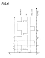
- the apparatus according to the invention aims at a jet of continuous dissection, but also a discontinuous stream formed periodic pulse trains of fire, one of which example of waveforms is represented taking place in time in Figure 6 and described below as well that single shot pulse sequences for special applications.
- Figure 1 shows in the form of a diagram synoptic constitution by its functions of the distributor according to the invention.
- a central unit UC controls and manages the entire operation of the device. She is connected to the general power supply ALIM and to different peripherals including a keyboard KEYBOARD, a memory MEMPRO program, a CICOP network for the exploitation of pneumatic controls of handpieces according to the in-service program and a CICP operating circuit a command by one or more pedal (s) CP.
- ALIM general power supply
- peripherals including a keyboard KEYBOARD, a memory MEMPRO program, a CICOP network for the exploitation of pneumatic controls of handpieces according to the in-service program and a CICP operating circuit a command by one or more pedal (s) CP.
- the central unit UC controls and manages the operation of the control assemblies of each of the two basic pathways, the No. 1 jet dissection pathway high pressure referenced HP jet and the No. 2 way of flow wash with adjustable flow referenced jet DEBIT.
- command sets are means of command in closing-opening of flows in fluidic connections from the device to the parts to hand.
- the command sets in the example represented are two electromechanical sets ESCA1 and ESCA2 respectively for each of the No. 1 and n ° 2.
- these engines can be for example of the DC type said variable frequency.
- Position detectors such as 19 and 20 are mounted for each track in the vicinity of the cams. They inform the central unit UC by the lines DECP01 and DECP02 on the cam positions of the two lanes n ° 1 and n ° 2.
- Cams are for example like those represented in the form of disks full circular circular hollow sector 21 or 22, fixed or adjustable angular opening.
- the song of disk actuates on a closing-opening means Sterile duct ordered either directly either via a moving part 23.
- a moving part 23 can be a lever, a finger, a blade, a rod or other animated movement alternative between a closed position and a position of release of the conduit.
- the cam can operate directly or indirectly a finger or a lever acting in pinching or crushing on the flexible duct in which the liquid passes under pressure or in flow or the gaseous fluid in depression of the suction path to realize pulses periodicals of the impulse regime.
- these are mounted for the same path on the same tree provided with structures longitudinal for example a splined shaft.
- each cam corresponds to an inactive state of the actuating piece on the conduit therefore to a passage of the fluid. That sector is fixed or adjustable so as to be able to modify the duration of action of the jet.
- the repetition frequency of the periodic phenomenon is given by the central unit UC from pre-established and recorded operating programs in MEMPRO corresponding to optimal values that emerge from representative trials of typical cases use. We thus determine relations cyclical according to the medical specialties and surgical procedures and the particular modes of intervention.
- One of the originalities of the sets of closing-opening command is to be able to pass in a steady state mode or only for the liquid jet under pressure also for suction with limited angular displacement of the tree common example fluted on which are mounted the cams with or without a point shift of these between they.
- On the apparatus according to the invention can be connect special handpieces with different types of manual controls and in particular pneumatic controls based on one or more discontinuity (s) of pressure or depression used as control signal for the device according to the invention.
- ducts connected to the source of pressure or depression are used to initiate a change in pressure or depression by a digital action of the user in order to serve as a control signal.
- An annex module MOPET concerns the routes of pneumatic controls of handpieces.
- This module pass a plurality of 1 to n ducts from the SOSPI suction source intended for be connected as control lines pneumatic handpieces with this type of ordered.
- Each control line line features a sensor or detector, DEP1, DEP2, ..., DEPn, sensitive to a variation of pressure and / or flow and connected via CICOP circuit to the unit Central UC.
- the pressure discontinuity signals are interpreted by the central unit UC and executed according to the internal program.
- sensors or detectors it can be electrical, magnetic, resistive contacts or others, sensors and sensors sensitive to pressure, but also flow-sensitive elements. The modification of these or the signal that they can to emit will result in a command pulse.
- the number of successive pulses can correspond to a command code or a dimming in the intensity of the commanded quantity.
- the number of pneumatic control ducts is not limited. It matches the needs of the parts the total number of which determines the capacity of the the apparatus according to the invention.
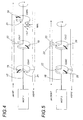
- the command set of this channel acts on a high-pressure flexible duct jet HP and on a ASPI1 flexible suction duct and on a set MAL air through a FILT filter ensuring the release of the suction.
- the command set of this route is consists of a MOT1 DC motor told to variable frequency resulting in the same tree, for example fluted example, three cams actuating devices closing and releasing a liquid conduit high pressure HP jet and suction ASPI1.
- the cams are each specialized. We distinguishes a first high liquid jet cam pressure CJL1 which controls the high-pressure fire, a CDA1 suction cam which controls the suction and a CMAL vent cam that controls the venting periodical MAL on the suction pipe ASPI1.
- Each cam has a solid angular sector and a recessed area. Full sector controls a device closing the conduit for example to push.
- the ESCA1 command set of the way of dissection may include only the two CJL1 cams and CDA1 allowing a periodic continuation of the shot without intermediate loosening of the fabric, that is to say without periodic venting MAL.
- the control unit can operate in continuous jet or pulsed jet.
- he is a fixed position of the cams in a given configuration.
- it is a continuous rotation of the MOT1 engine at a constant speed given causing a diet impulse determined by the speed of rotation of the motor, by the respective positions of the cams angularly offset and by the angular aperture of the recessed areas of the cams.
- the cams When starting the camera, the cams are in an open position, that is, their sector angular hollow is in front of the ducts, then the MOT1 motor is rotated at low speed and then reaches the speed corresponding to the frequency of the selected diet.
- the device allows a continuous regime on the Dissection route. It then works on command manually by occasional angular displacements and limited cams between a closed position and an open position of the corresponding conduit.
- This path is intended for all applications requiring a flow rather than a pressure. This is washing, but also rinsing, of the irrigation of the natural cavities of the human body during surgical procedures and all other applications of this type in the fields of surgery and medicine in general.
- the command set of this channel acts on a jet duct Flexible flow of liquid transport sterile under low pressure depending on the flow rate imposed by the handpiece used and on a flexible conduit aspirator ASPI2 connected to the suction source.
- the control assembly is formed of an engine DC MOT2 with variable frequency actuating the common shaft 18, for example fluted, carrying two CJL2 and CDA2 cams integral with this tree and angularly offset between them.
- the cams are arranged, for example in phase opposition, i.e. offset by 180 ° angle.
- the MOT2 engine is not used in rotation continues as the MOT1 engine, but in command of limited angular displacement between a position opening of one of the ducts and a position correlative wash with suction closure then suction with closure of the washing jet.
- the cams are circular and have a full angular sector followed by a angular sector hollowed out according to an angular opening determined fixed or adjustable.
- the cams operate in pushed by their singing a mechanical device shutter for example a guided push element: rod, bar ..., coming into contact with crush with the flexible duct facing towards a closure almost total and then an opening during the passage of recessed area.
- a mechanical device shutter for example a guided push element: rod, bar ...
- Position detectors of the cam or presence in a given area of the full sector or hollow sector are planned to inform the unit center on position and deviation or excursion angular to order. These detectors are represented in the figures in the form of stirrups 20 fixed by relative to the body of each cam.
- An action on the pneumatic control of a handpiece or on the CP pedal causes the rotation MOT2 motor until the complete opening of the duct ASPI2 suction and motor shutdown when the recessed area of the CDA2 depression cam is located at the control pushbutton. At the same time, FLOW liquid pipe DEBIT remains closed.
- a new command action will cause the MOT2 motor limited rotation until presentation of the recessed area of the CJL2 cam of the liquid jet of washing at the control pusher allowing so again the passage of the sterile wash liquid or rinsing. At the same time, the depression leads closes and stays closed.
- cams will present a central opening of shape complement to adjust to the splines. It is a grooved tree for every group of cams or a single splined shaft for all the cams.
- connection interface For safety and convenience, we can provide on the outlet side of the ducts a connection interface. It can be a wall or a pivoting panel (not shown) forming a door sentence bearing the bases of connection themselves connected to the ends of flexible ducts of the appliance on which the cams.
- This wall allows, when folded and locked, to cut any flow in the ducts power supply and therefore an untimely exit from liquid while the handpiece (s) are not still connected.
- the wall of the door condemns the passage of any flow of the ducts in the apparatus to level of their ends before the fittings of junction for example by pinching or folding of ducts. This conviction persists until the opening of the door.
- the apparatus according to the invention is a device multifunctional and multipurpose. However, it has been designed especially to implement on its way No. 1 of high pressure the process of generating a jet sterile pulsed-aspirated liquid, subject to protection parallel to the name of the applicant.
- the process described in this protection parallel, is characterized in that it implements a pressurized liquid path and a pneumatic path suction and in that we order the shot periodic pressure jet during application periodic aspiration.
- the process is completed in that one periodically performs a neutralization of Vacuum aspiration just after closing suction pipe for example by venting the suction duct and for higher speeds frequency a periodic discharge of pressure residual on the pressure lane.
- the shot is done with some delay compared to the beginning of aspiration.
- Shooting is preferably done in the first half of the pulse width of aspiration and preferably stops before the start from the second half.
- the venting takes place after the cut off the suction and preferably but not obligatorily just after this break.
- the breather is short and follows immediately the end of aspiration.
- the frequency of recurrence of the diet pulse and pulse width can vary. These variations depend on the application surgical procedure, ie the type of procedure, organ or targeted tissue as well as depth of intervention in the human body.
Landscapes
- Health & Medical Sciences (AREA)
- Heart & Thoracic Surgery (AREA)
- Life Sciences & Earth Sciences (AREA)
- General Health & Medical Sciences (AREA)
- Surgery (AREA)
- Veterinary Medicine (AREA)
- Engineering & Computer Science (AREA)
- Biomedical Technology (AREA)
- Public Health (AREA)
- Animal Behavior & Ethology (AREA)
- Anesthesiology (AREA)
- Hematology (AREA)
- Vascular Medicine (AREA)
- Nuclear Medicine, Radiotherapy & Molecular Imaging (AREA)
- Pulmonology (AREA)
- Medical Informatics (AREA)
- Molecular Biology (AREA)
- Surgical Instruments (AREA)
- Infusion, Injection, And Reservoir Apparatuses (AREA)
- External Artificial Organs (AREA)
Description
- une voie de distribution de liquide sous pression reliée à une pièce à main de dissection pour un fonctionnement en régime pulsé-aspiré ou continu ;
- une voie de distribution de liquide sous débit reliée à une pièce à main de lavage-rinçage ou d'irrigation pour un fonctionnement en régime continu à commande manuelle ;
- un module de commande engendrant un régime impulsionnel périodique de fermeture-ouverture des flux sur la voie de pression selon des séquences prédéterminées ;
- des fonctions spécifiques permettant à la pièce à main d'être commandée manuellement par une discontinuité pneumatique.
- un conduit de distribution du liquide stérile sous pression relié à une pièce à main de dissection ;
- un conduit de dépression relié à la pièce à main de dissection ;
- des moyens séquentiels synchronisés de fermeture-ouverture périodique de la dépression agissant sur la voie de dépression ;
- des moyens synchronisés avec les premiers de mise à l'air périodique de la dépression, agissant sur la voie de dépression ;
- des moyens synchronisés de fermeture-ouverture périodique du liquide sous pression de dissection.
- un conduit de distribution du liquide stérile selon un débit réglable relié à une pièce à main de lavage-rinçage ou d'irrigation ;
- un conduit de dépression réglable relié à la même pièce à main de lavage-rinçage ;
- des moyens de réglage du débit du liquide stérile et de la dépression ;
- des moyens de commande manuelle de fermeture-ouverture du flux de liquide ;
- des moyens de commande manuelle de fermeture-ouverture de la dépression liés aux moyens de commande précédents pour le liquide.
- on dispose de deux voies pouvant fonctionner simultanément indépendamment l'une de l'autre reliée chacune à une pièce à main spécifique dont l'usage peut être simultané ou successif dans le cadre d'un travail sur un même champ opératoire,
- les deux voies peuvent distribuer le fluide de travail et aspirer en régime pulsé ou continu indépendamment l'une de l'autre,
- les séquences programmées produisant les formes d'ondes adaptées des régimes impulsionnels sont préenregistrées et spécifiques d'une application donnée. Elles constituent l'optimum pour cette application,
- les branchements et la disposition des conduits sont facilités,
- la stérilité est garantie à tous les niveaux,
- il est prévu un circuit spécial pour mettre en oeuvre les commandes de fonctionnement des pièces à main à partir de la variation pneumatique d'un fluide,
- les moyens mécaniques assurent les interruptions des flux des fluides dans des conditions stériles,
- il est possible de relier les deux voies à une pièce à main mixte unique,
- l'appareil permet de réaliser un tir par impulsions périodiques de faible durée ou un tir unique d'une seule impulsion,
- le tir périodique de faible durée s'effectue sur un tissu tendu par l'aspiration,
- on contrôle mieux la profondeur de l'incision,
- on bénéficie d'une meilleure visibilité du travail de dissection effectué et du champ opératoire.
- la figure 1 : une vue synoptique générale de l'appareil de distribution selon l'invention ;
- la figure 2 : une vue schématique illustrant le principe sur les deux voies de base de l'appareil selon l'invention ;
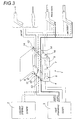
- la figure 3 : une vue générale schématique montrant l'appareil dans un montage d'utilisation avec les générateurs et les pièces à main ;
- les figures 4 et 5 : des vues schématiques de détail des deux voies de base avec les ensembles de commande correspondants ;
- la figure 6 : un graphique montrant un exemple de déroulement dans le temps des actions périodiques de commande des trois variables de la voie de dissection.
- phase 1 : début de l'aspiration,
- phase 2 : tir du jet sous pression pendant une courte durée à l'intérieur de l'impulsion d'aspiration,
- phase 3 : poursuite de l'aspiration après le tir,
- phase 4 : mise à l'air pendant la coupure de l'aspiration,
- phase 5 : poursuite de la coupure de l'aspiration jusqu'à la prochaine période.
- fréquence de récurrence : 1 Hz
- largeur d'impulsion de tir : 100 ms
- largeur d'impulsion d'aspiration : 400 ms
- repos d'aspiration : 600 ms
- largeur d'impulsion de mise à l'air : 300 ms
- décalage entre la fin de l'impulsion d'aspiration et la mise à l'air : faible.
Claims (25)
- Appareil pour la génération de jets pulsés de liquide avec aspiration parallèle sur au moins deux voies à partir d'un liquide stérile de travail, les deux voies pouvant être reliées à au moins une pièce à main d'intervention chirurgicale ou médicale, appareil pouvant être raccordé à une source de liquide stérile sous pression (SOSPE) et à une source de dépression (SOSPI) caractérisé en ce que :les au moins deux voies de liquide stérile de travail, sont d'une part une voie dite voie sous pression (HP) avec aspiration parallèle pour des travaux de dissection, et d'autre part une voie dite voie sous débit (DEBIT) avec aspiration parallèle pour des travaux de lavage-rinçage ou d'irrigation, chacune de cesdites voies pouvant être raccordée à une pièce à main spécifique, l'une éjectant un ou des jets de liquide sous pression et sortant de l'autre pièce à main un jet en débit, ou les deux voies pouvant être raccordées à une pièce à main mixte de dissection et de lavage-rinçage,chacune de cesdites au moins deux voies est constituée de deux conduits, l'un dit conduit d'amenée de liquide et l'autre dit conduit de dépression,chacune de cesdites au moins deux voies comporte des moyens de commande pour commander en fermeture-ouverture chacun des conduits desdites voies afin de permettre un fonctionnement de l'appareil en régime périodique à fréquence réglable ou prédéterminée ou en régime continu,l'appareil comprend une mémoire (MEMPRO) dans laquelle sont enregistrés des modes de fonctionnement préétablis en liaison avec une unité centrale (UC) pour la génération de jets pulsés ou continus à partir de commandes manuelles (6) pouvant être initiées par l'utilisateur.
- Appareil générateur selon la revendication 1 caractérisé en ce que ladite voie sous pression comporte une commande de mise à l'air périodique de l'aspiration (CMAL) après la coupure de cette aspiration.
- Appareil générateur selon la revendication 1 caractérisé en ce que les moyens de commande de fonctionnement de chacun des conduits de ladite voie sous pression peuvent être synchronisés entre eux pendant l'utilisation pour la génération de jets pulsés-aspirés.
- Appareil générateur selon la revendication 3 caractérisé en ce que ladite voie sous pression comporte une commande de mise à l'air périodique de l'aspiration (CMAL) après la coupure de cette aspiration.
- Appareil générateur selon l'une quelconque des revendications précédentes caractérisé en ce que les moyens de commande des flux (ESCA1, ESCA2) sont électromécaniques.
- Appareil générateur selon la revendication 5 caractérisé en ce que les moyens de commande des flux (ESCA1, ESCA2) sont formés de deux ensembles distincts constitués chacun d'au moins deux cames montées décalées angulairement entre elles sur un arbre commun (17, 18) et actionnées par un moteur électrique (MOT1) pour ladite voie sous pression et par un moteur électrique (MOT2) pour ladite voie sous débit.
- Appareil générateur selon la revendication 6 caractérisé en ce que les cames sont circulaires et présentent au moins un secteur angulaire plein et un secteur angulaire vide ou évidé (21, 22).
- Appareil générateur selon la revendication 7 caractérisé en ce que le secteur évidé (21) ou (22) est d'angle d'ouverture réglable.
- Appareil générateur selon l'une quelconque des revendications 7 ou 8 caractérisé en ce que chaque came est adaptée pour actionner en mouvement par le passage entre le secteur évidé (21, 22) et le secteur plein et inversement un élément mobile (23) qui assure par son déplacement, la fermeture puis l'ouverture du flux dans un conduit de liquide ou dans un conduit de dépression correspondant (ASPI1, ASPI2).
- Appareil selon l'une quelconque des revendications de 6 à 8 caractérisé en ce que l'arbre commun (17, 18) de chaque groupe de cames ou l'arbre commun (17, 18) à toutes les cames est cannelé.
- Appareil générateur selon l'une quelconque des revendications précédentes caractérisé en ce que lesdits conduits d'amenée de liquide desdites voies sous pression et sous débit (ASPI1, ASPI2) sont souples et en ce que la fermeture est réalisée par un moyen d'écrasement desdits conduits d'amenée de liquide ou de dépression.
- Appareil générateur selon l'une quelconque des revendications de 1 à 10 caractérisé en ce que lesdits conduits d'amenée de liquide ou de dépression desdites voies sous pression et sous débit (ASPI1) ou (ASPI2) sont souples et en ce que la fermeture est réalisée par un moyen de pincement desdits conduits d'amenée de liquide ou de dépression.
- Appareil générateur selon la revendication 6 caractérisé en ce que la voie du liquide sous pression comporte trois cames décalées angulairement entre elles dont une came (CJL1) de fermeture-ouverture du conduit d'amenée de liquide sous pression, une came (CDA1) de fermeture-ouverture du conduit de dépression et une came (CMAL) de mise à l'air périodique de ce conduit de dépression au rythme des jets pulsés pour l'obtention d'un jet pulsé-aspiré suivi d'une détente provoquant le relâchement du tissu.
- Appareil générateur selon la revendication 13 caractérisé en ce que la mise à l'air (MAL) s'effectue à travers un filtre (FILT).
- Appareil générateur selon la revendication 13 caractérisé en ce que ladite voie sous pression ne comprend pas de mise à l'air (MAL).
- Appareil générateur selon la revendication 6 caractérisé en ce que ladite voie sous débit comporte deux cames décalées entre elles dont une came de fermeture-ouverture (CJL2) dudit conduit d'amenée de liquide et une came de fermeture-ouverture (CDA2) dudit conduit de dépression (ASPI2).
- Appareil générateur selon la revendication 16 caractérisé en ce que les cames (CJL2, CDA2) sont portées par le même arbre et décalées angulairement de 180°.
- Appareil générateur selon l'une quelconque des revendications précédentes de 6 à 10 et de 13 à 17 caractérisé en ce que les cames sont équipées d'au moins un détecteur (19, 20) ou d'au moins un capteur de position.
- Appareil générateur selon la revendication 1 caractérisé en ce que les moyens de commande (ESCA1) de ladite voie sous pression sont prévus pour la génération d'un jet continu ou d'un jet pulsé-aspiré périodique à caractéristiques réglables avec mise à l'air périodique (MAL) au rythme de la pulsation.
- Appareil générateur selon l'une quelconque des revendications précédentes de 5 à 18 caractérisé en ce que ladite voie sous débit fonctionnant en continu avec aspiration simultanée ou successive comporte une commande de déplacement angulaire limité des cames.
- Appareil générateur selon la revendication 1 en combinaison avec au moins une pièce à main pour sa commande manuelle de fonctionnement par l'utilisateur par discontinuité de pression ou de dépression.
- Appareil générateur selon la revendication 21 caractérisé en ce que les commandes manuelles (6) des pièces à main sont des conduits de dépression adaptés pour relier la source de dépression (SOSPI) aux pièces à main en passant par ou à côté d'un capteur ou d'un détecteur correspondant (DEP1, DEP2,..DEPn) sensible à la pression ou à un débit.
- Appareil générateur selon la revendication 1 en combinaison avec une commande manuelle qui est au moins une pédale (CP).
- Appareil générateur selon la revendication 1 caractérisé en ce que lesdits conduits d'amenée de liquide sortent de l'appareil par une interface de sécurité assurant le raccordement sous la forme d'un panneau pivotant portant les socles des prises de raccordement, ce panneau pivotant formant porte de condamnation permet lorsqu'il est rabattu et verrouillé, d'arrêter tout passage dans les conduits d'amenée de liquide pendant l'utilisation de l'appareil.
- Appareil générateur selon la revendication 24 caractérisé en ce que le passage de fluide dans lesdits conduits d'amenée de liquide dans lesdites voies sous pression et sous débit est arrêté par pincement ou repliement de ces conduits suite au rabattement par pivotement du panneau pivotant formant porte de condamnation.
Applications Claiming Priority (3)
| Application Number | Priority Date | Filing Date | Title |
|---|---|---|---|
| FR9808183 | 1998-06-24 | ||
| FR9808183A FR2780268B1 (fr) | 1998-06-24 | 1998-06-24 | Appareil de distribution a deux voies d'un liquide sterile de travail selon des sequences predeterminees pour des applications chirurgicales ou medicales a l'aide d'au moins une piece a main |
| PCT/FR1999/001511 WO1999066848A1 (fr) | 1998-06-24 | 1999-06-23 | Appareil de distribution a deux voies d'un liquide sterile de travail pour des applications medicales |
Publications (2)
| Publication Number | Publication Date |
|---|---|
| EP1089666A1 EP1089666A1 (fr) | 2001-04-11 |
| EP1089666B1 true EP1089666B1 (fr) | 2005-05-11 |
Family
ID=9527951
Family Applications (1)
| Application Number | Title | Priority Date | Filing Date |
|---|---|---|---|
| EP99957140A Expired - Lifetime EP1089666B1 (fr) | 1998-06-24 | 1999-06-23 | Appareil de distribution a deux voies d'un liquide sterile de travail pour des applications medicales |
Country Status (9)
| Country | Link |
|---|---|
| US (1) | US6322533B1 (fr) |
| EP (1) | EP1089666B1 (fr) |
| JP (1) | JP2003524439A (fr) |
| AT (1) | ATE295124T1 (fr) |
| AU (1) | AU4271299A (fr) |
| DE (1) | DE69925272T8 (fr) |
| ES (1) | ES2242431T3 (fr) |
| FR (1) | FR2780268B1 (fr) |
| WO (1) | WO1999066848A1 (fr) |
Families Citing this family (20)
| Publication number | Priority date | Publication date | Assignee | Title |
|---|---|---|---|---|
| DE19912844A1 (de) | 1999-03-22 | 2000-09-28 | Saphir Medical Products Gmbh | Verwendung eines Schneidegerätes, welches ein Fluid als Schneidemedium einsetzt, zur chirurgischen Behandlung |
| US6375635B1 (en) | 1999-05-18 | 2002-04-23 | Hydrocision, Inc. | Fluid jet surgical instruments |
| US6511493B1 (en) | 2000-01-10 | 2003-01-28 | Hydrocision, Inc. | Liquid jet-powered surgical instruments |
| US6451017B1 (en) | 2000-01-10 | 2002-09-17 | Hydrocision, Inc. | Surgical instruments with integrated electrocautery |
| DE10033283A1 (de) * | 2000-07-07 | 2002-01-24 | Pein Andreas Medizintech Gmbh | Verwendung eines flüssigen Medikamentes zur Behandlung von Dissektionsebenen Resektionsflächen an einer biologischen Struktur und zur gleichzeitigen Trennung der biologischen Struktur und Hochdruckflüssigkeitsstrahleinrichtung zur Durchführung des Verfahrens |
| DE60221239T2 (de) | 2001-04-27 | 2008-04-10 | HydroCision, Inc., Billerica | Hochdruckeinwegpumpenkassette zur anwendung auf medizinischem gebiet |
| WO2003045259A1 (fr) | 2001-11-21 | 2003-06-05 | Hydrocision Inc. | Instruments chirurgicaux a jet de liquide comprenant des ouvertures de canaux alignees sur le faisceau de jets |
| DE10233053B4 (de) * | 2002-07-19 | 2005-02-24 | W.O.M. World Of Medicine Ag | Vorrichtung zum Durchspülen einer Körperhöhle |
| US8162966B2 (en) | 2002-10-25 | 2012-04-24 | Hydrocision, Inc. | Surgical devices incorporating liquid jet assisted tissue manipulation and methods for their use |
| US10363061B2 (en) | 2002-10-25 | 2019-07-30 | Hydrocision, Inc. | Nozzle assemblies for liquid jet surgical instruments and surgical instruments for employing the nozzle assemblies |
| US7846126B2 (en) * | 2003-07-14 | 2010-12-07 | Abbott Medical Optics, Inc. | System and method for modulated surgical procedure irrigation and aspiration |
| DE102004057366B4 (de) * | 2004-11-27 | 2009-04-09 | Erbe Elektromedizin Gmbh | Einrichtung für ein Wasserstrahlchirurgiegerät |
| US9254144B2 (en) | 2007-03-30 | 2016-02-09 | Covidien Lp | Methods and apparatus for thrombectomy system |
| JP5115088B2 (ja) | 2007-08-10 | 2013-01-09 | セイコーエプソン株式会社 | 手術具 |
| JP2012152423A (ja) * | 2011-01-27 | 2012-08-16 | Seiko Epson Corp | 流体噴射装置およびその制御方法、並びに手術装置 |
| WO2012124653A1 (fr) * | 2011-03-17 | 2012-09-20 | オリンパスメディカルシステムズ株式会社 | Dispositif d'émission de liquide ainsi que dispositif de traitement pour soins médicaux |
| JP5585713B2 (ja) * | 2013-10-28 | 2014-09-10 | セイコーエプソン株式会社 | 流体噴射装置 |
| JP5773039B2 (ja) * | 2014-07-09 | 2015-09-02 | セイコーエプソン株式会社 | 制御装置、流体噴射装置及び流体噴射方法 |
| US10492821B2 (en) | 2016-06-24 | 2019-12-03 | Hydrocision, Inc. | Selective tissue removal treatment device |
| US10485568B2 (en) | 2016-06-24 | 2019-11-26 | Hydrocision, Inc. | Selective tissue removal treatment device |
Family Cites Families (29)
| Publication number | Priority date | Publication date | Assignee | Title |
|---|---|---|---|---|
| FR1378042A (fr) | 1963-05-25 | 1964-11-13 | Vanne télécommandée ou à action directe et son appareillage pour aspiration médicochirurgicale | |
| US4205677A (en) | 1978-02-27 | 1980-06-03 | Engstrom William R | Cardiotomy suction control system and valve |
| DE3019115C2 (de) | 1980-05-20 | 1982-10-28 | Aesculap-Werke Ag Vormals Jetter & Scheerer, 7200 Tuttlingen | Instrument zur Ablösung eines Blutpfropfens |
| US4655197A (en) * | 1982-12-01 | 1987-04-07 | Snyder Laboratories, Inc. | Lavage system with variable frequency, flow rate and pressure |
| US4519385A (en) | 1982-12-01 | 1985-05-28 | Snyder Laboratories, Inc. | Lavage handpiece |
| US4702733A (en) * | 1985-11-22 | 1987-10-27 | Innovative Surgical Products, Inc. | Foot actuated pinch valve and high vacuum source for irrigation/aspiration handpiece system |
| US4759349A (en) | 1986-02-24 | 1988-07-26 | Vitalmetrics, Inc. | Surgical instrument having a heat sink for irrigation, aspiration, and illumination |
| US4676779A (en) * | 1986-03-12 | 1987-06-30 | Mayoral Armando Gamboa | Medical aspirator system |
| DE3715418A1 (de) | 1986-05-08 | 1987-11-12 | Olympus Optical Co | Lithotom |
| CH676661A5 (fr) | 1988-06-16 | 1991-02-28 | Claude F Dr Rausis | |
| US5322506A (en) * | 1989-07-31 | 1994-06-21 | C. R. Bard, Inc. | Irrigation system with high flow bypass for use with endoscopic procedure |
| CA2048120A1 (fr) | 1990-08-06 | 1992-02-07 | William J. Drasler | Methode et appareil de thrombectomie |
| CA2048239A1 (fr) * | 1990-11-08 | 1992-05-09 | William J. Drasler | Appareil a atherectomie a jet d'eau |
| DE4200976C2 (de) * | 1992-01-16 | 1995-08-24 | Andreas Pein | Vorrichtung zum Trennen einer biologischen Struktur, insbesondere des menschlichen Gewebes |
| US5308673A (en) | 1992-05-07 | 1994-05-03 | Minnesota Mining And Manufacturing Company | Stitchbonded absorbent articles and method of making same |
| AU5666694A (en) | 1992-11-13 | 1994-06-08 | William J. Drasler | Thrombectomy and tissue removal method and device |
| FR2706276A1 (fr) * | 1993-06-09 | 1994-12-23 | Philibert Marc | Bistouri à jet de liquide. |
| CA2127637C (fr) | 1993-07-26 | 2006-01-03 | Scott Bair | Instrument chirurgical de coupure a jet de liquide |
| US5735815A (en) | 1993-07-26 | 1998-04-07 | Sentinel Medical, Inc. | Method of using fluid jet surgical cutting tool |
| WO1996001079A1 (fr) | 1994-07-01 | 1996-01-18 | Scimed Life Systems, Inc. | Dispositif intravasculaire utilisant un fluide pour extraire le materiau occlusif |
| US5605537A (en) * | 1994-08-08 | 1997-02-25 | Ivey; Jack L. | Endoscopic device |
| CA2220689A1 (fr) | 1995-05-10 | 1996-11-14 | Cardiogenesis Corporation | Systeme de traitement ou de diagnostic pour le tissu cardiaque |
| US5871462A (en) | 1995-06-07 | 1999-02-16 | Hydrocision, Inc. | Method for using a fluid jet cutting system |
| FR2737103B1 (fr) | 1995-07-24 | 1997-10-03 | Saphir Medical Sa | Instrument chirurgical a jet de liquide, tel que bistouri a jet de liquide, a usage unique |
| US6152918A (en) | 1996-04-05 | 2000-11-28 | Eclipse Surgical Technologies, Inc. | Laser device with auto-piercing tip for myocardial revascularization procedures |
| FR2750053B1 (fr) * | 1996-06-21 | 1999-01-15 | Saphir Medical Sa | Generateur-distributeur bi-fonction de debit et/ou de pression |
| US6063069A (en) | 1997-05-19 | 2000-05-16 | Micro Therapeutics Inc. | Method and apparatus for power lysis of a thrombus |
| US6030399A (en) | 1997-06-04 | 2000-02-29 | Spectrx, Inc. | Fluid jet blood sampling device and methods |
| IL136643A0 (en) | 1997-12-31 | 2001-06-14 | Hydrocision Inc | Fluid jet cutting system for cardiac applications |
-
1998
- 1998-06-24 FR FR9808183A patent/FR2780268B1/fr not_active Expired - Fee Related
-
1999
- 1999-06-23 WO PCT/FR1999/001511 patent/WO1999066848A1/fr not_active Ceased
- 1999-06-23 DE DE69925272T patent/DE69925272T8/de not_active Expired - Fee Related
- 1999-06-23 AT AT99957140T patent/ATE295124T1/de not_active IP Right Cessation
- 1999-06-23 US US09/338,804 patent/US6322533B1/en not_active Expired - Fee Related
- 1999-06-23 ES ES99957140T patent/ES2242431T3/es not_active Expired - Lifetime
- 1999-06-23 AU AU42712/99A patent/AU4271299A/en not_active Abandoned
- 1999-06-23 EP EP99957140A patent/EP1089666B1/fr not_active Expired - Lifetime
- 1999-06-23 JP JP2000555538A patent/JP2003524439A/ja active Pending
Also Published As
| Publication number | Publication date |
|---|---|
| DE69925272T8 (de) | 2006-04-27 |
| JP2003524439A (ja) | 2003-08-19 |
| DE69925272T2 (de) | 2006-02-23 |
| DE69925272D1 (de) | 2005-06-16 |
| AU4271299A (en) | 2000-01-10 |
| ES2242431T3 (es) | 2005-11-01 |
| WO1999066848A1 (fr) | 1999-12-29 |
| FR2780268A1 (fr) | 1999-12-31 |
| EP1089666A1 (fr) | 2001-04-11 |
| US6322533B1 (en) | 2001-11-27 |
| FR2780268B1 (fr) | 2000-09-29 |
| ATE295124T1 (de) | 2005-05-15 |
Similar Documents
| Publication | Publication Date | Title |
|---|---|---|
| WO1999066848A1 (fr) | Appareil de distribution a deux voies d'un liquide sterile de travail pour des applications medicales | |
| EP2575648B1 (fr) | Générateur de jets pulses moyenne et haute pression d'un liquide en vue d'applications médicales et chirurgicales | |
| EP0238378B1 (fr) | Appareil d'injection ou de prélèvement de substances | |
| US11166702B2 (en) | Quick cycle biopsy system | |
| EP1087707B1 (fr) | Piece a main de commande pneumatique d'un appareil chirurgical | |
| EP0915715B1 (fr) | Générateur-distributeur bi-fonctionde liquide notamment stérile | |
| EP0538200B1 (fr) | Appareil d'obturation par le vide de canaux radiculaires dentaires | |
| EP0521119B1 (fr) | Equipement pour nettoyer des cavites | |
| FR2806617A1 (fr) | Instrument dentaire rotatif et procedes d'utilisation associes | |
| US9234516B2 (en) | Fluid ejection device and medical device | |
| CN102151164A (zh) | 液体喷射装置 | |
| EP0094470A1 (fr) | Appareil portable de traitement dentaire | |
| US6428507B1 (en) | Method and device for rinsing | |
| FR2657489A1 (fr) | Dispositif, tel que generateur de plasma, a circulation sequentielle de fluides. | |
| FR2800271A1 (fr) | Appareil de phacoemulsification | |
| JP4158021B2 (ja) | 歯科用幹線管路循環式給水及び残留水排出システム | |
| WO2021038177A1 (fr) | Dispositif chirurgical comportant une tige présentant à son extrémité distale un manchon déformable entourant ladite tige | |
| JP2004359340A (ja) | 液体充填ノズルおよび充填方法 | |
| EP4477374A1 (fr) | Système d'impression 3d avec dérivation | |
| FR2873287A1 (fr) | Perfectionnement aux appareillages chirurgicaux de type phacoemulsificateurs bi-manuels | |
| EP1164947A1 (fr) | Appareil chirurgical a jet de liquide sous pression pour la revascularisation transmyocardiale | |
| FR2710125A1 (fr) | Procédé et dispositif de distribution séquentielle de fluides. | |
| JP2024065297A (ja) | 医療用装置、および洗浄方法 | |
| JP2014061231A (ja) | ポンプ装置 |
Legal Events
| Date | Code | Title | Description |
|---|---|---|---|
| PUAI | Public reference made under article 153(3) epc to a published international application that has entered the european phase |
Free format text: ORIGINAL CODE: 0009012 |
|
| 17P | Request for examination filed |
Effective date: 20010116 |
|
| AK | Designated contracting states |
Kind code of ref document: A1 Designated state(s): AT BE CH CY DE DK ES FI GB GR IE IT LI LU MC NL PT SE |
|
| 17Q | First examination report despatched |
Effective date: 20031008 |
|
| RAP1 | Party data changed (applicant data changed or rights of an application transferred) |
Owner name: ESCHMANN HOLDINGS LIMITED |
|
| GRAP | Despatch of communication of intention to grant a patent |
Free format text: ORIGINAL CODE: EPIDOSNIGR1 |
|
| GRAS | Grant fee paid |
Free format text: ORIGINAL CODE: EPIDOSNIGR3 |
|
| GRAA | (expected) grant |
Free format text: ORIGINAL CODE: 0009210 |
|
| AK | Designated contracting states |
Kind code of ref document: B1 Designated state(s): AT BE CH CY DE DK ES FI GB GR IE IT LI LU MC NL PT SE |
|
| PG25 | Lapsed in a contracting state [announced via postgrant information from national office to epo] |
Ref country code: NL Free format text: LAPSE BECAUSE OF FAILURE TO SUBMIT A TRANSLATION OF THE DESCRIPTION OR TO PAY THE FEE WITHIN THE PRESCRIBED TIME-LIMIT Effective date: 20050511 Ref country code: IE Free format text: LAPSE BECAUSE OF FAILURE TO SUBMIT A TRANSLATION OF THE DESCRIPTION OR TO PAY THE FEE WITHIN THE PRESCRIBED TIME-LIMIT Effective date: 20050511 Ref country code: FI Free format text: LAPSE BECAUSE OF FAILURE TO SUBMIT A TRANSLATION OF THE DESCRIPTION OR TO PAY THE FEE WITHIN THE PRESCRIBED TIME-LIMIT Effective date: 20050511 Ref country code: AT Free format text: LAPSE BECAUSE OF FAILURE TO SUBMIT A TRANSLATION OF THE DESCRIPTION OR TO PAY THE FEE WITHIN THE PRESCRIBED TIME-LIMIT Effective date: 20050511 |
|
| REG | Reference to a national code |
Ref country code: GB Ref legal event code: FG4D Free format text: NOT ENGLISH |
|
| REG | Reference to a national code |
Ref country code: CH Ref legal event code: EP |
|
| REG | Reference to a national code |
Ref country code: IE Ref legal event code: FG4D Free format text: LANGUAGE OF EP DOCUMENT: FRENCH |
|
| REF | Corresponds to: |
Ref document number: 69925272 Country of ref document: DE Date of ref document: 20050616 Kind code of ref document: P |
|
| PG25 | Lapsed in a contracting state [announced via postgrant information from national office to epo] |
Ref country code: LU Free format text: LAPSE BECAUSE OF NON-PAYMENT OF DUE FEES Effective date: 20050623 Ref country code: CY Free format text: LAPSE BECAUSE OF FAILURE TO SUBMIT A TRANSLATION OF THE DESCRIPTION OR TO PAY THE FEE WITHIN THE PRESCRIBED TIME-LIMIT Effective date: 20050623 |
|
| PG25 | Lapsed in a contracting state [announced via postgrant information from national office to epo] |
Ref country code: MC Free format text: LAPSE BECAUSE OF NON-PAYMENT OF DUE FEES Effective date: 20050630 Ref country code: LI Free format text: LAPSE BECAUSE OF NON-PAYMENT OF DUE FEES Effective date: 20050630 Ref country code: CH Free format text: LAPSE BECAUSE OF NON-PAYMENT OF DUE FEES Effective date: 20050630 Ref country code: BE Free format text: LAPSE BECAUSE OF NON-PAYMENT OF DUE FEES Effective date: 20050630 |
|
| PG25 | Lapsed in a contracting state [announced via postgrant information from national office to epo] |
Ref country code: SE Free format text: LAPSE BECAUSE OF FAILURE TO SUBMIT A TRANSLATION OF THE DESCRIPTION OR TO PAY THE FEE WITHIN THE PRESCRIBED TIME-LIMIT Effective date: 20050811 Ref country code: GR Free format text: LAPSE BECAUSE OF FAILURE TO SUBMIT A TRANSLATION OF THE DESCRIPTION OR TO PAY THE FEE WITHIN THE PRESCRIBED TIME-LIMIT Effective date: 20050811 Ref country code: DK Free format text: LAPSE BECAUSE OF FAILURE TO SUBMIT A TRANSLATION OF THE DESCRIPTION OR TO PAY THE FEE WITHIN THE PRESCRIBED TIME-LIMIT Effective date: 20050811 |
|
| GBT | Gb: translation of ep patent filed (gb section 77(6)(a)/1977) |
Effective date: 20050818 |
|
| PG25 | Lapsed in a contracting state [announced via postgrant information from national office to epo] |
Ref country code: PT Free format text: LAPSE BECAUSE OF FAILURE TO SUBMIT A TRANSLATION OF THE DESCRIPTION OR TO PAY THE FEE WITHIN THE PRESCRIBED TIME-LIMIT Effective date: 20051019 |
|
| NLV1 | Nl: lapsed or annulled due to failure to fulfill the requirements of art. 29p and 29m of the patents act | ||
| REG | Reference to a national code |
Ref country code: ES Ref legal event code: FG2A Ref document number: 2242431 Country of ref document: ES Kind code of ref document: T3 |
|
| REG | Reference to a national code |
Ref country code: IE Ref legal event code: FD4D |
|
| REG | Reference to a national code |
Ref country code: CH Ref legal event code: PL |
|
| PLBE | No opposition filed within time limit |
Free format text: ORIGINAL CODE: 0009261 |
|
| STAA | Information on the status of an ep patent application or granted ep patent |
Free format text: STATUS: NO OPPOSITION FILED WITHIN TIME LIMIT |
|
| 26N | No opposition filed |
Effective date: 20060214 |
|
| BERE | Be: lapsed |
Owner name: ESCHMANN HOLDINGS LTD Effective date: 20050630 |
|
| PGFP | Annual fee paid to national office [announced via postgrant information from national office to epo] |
Ref country code: ES Payment date: 20090629 Year of fee payment: 11 |
|
| PGFP | Annual fee paid to national office [announced via postgrant information from national office to epo] |
Ref country code: GB Payment date: 20090612 Year of fee payment: 11 Ref country code: DE Payment date: 20090606 Year of fee payment: 11 |
|
| PGFP | Annual fee paid to national office [announced via postgrant information from national office to epo] |
Ref country code: IT Payment date: 20090627 Year of fee payment: 11 |
|
| GBPC | Gb: european patent ceased through non-payment of renewal fee |
Effective date: 20100623 |
|
| PG25 | Lapsed in a contracting state [announced via postgrant information from national office to epo] |
Ref country code: IT Free format text: LAPSE BECAUSE OF NON-PAYMENT OF DUE FEES Effective date: 20100623 |
|
| PG25 | Lapsed in a contracting state [announced via postgrant information from national office to epo] |
Ref country code: DE Free format text: LAPSE BECAUSE OF NON-PAYMENT OF DUE FEES Effective date: 20110101 |
|
| REG | Reference to a national code |
Ref country code: ES Ref legal event code: FD2A Effective date: 20110718 |
|
| PG25 | Lapsed in a contracting state [announced via postgrant information from national office to epo] |
Ref country code: GB Free format text: LAPSE BECAUSE OF NON-PAYMENT OF DUE FEES Effective date: 20100623 Ref country code: ES Free format text: LAPSE BECAUSE OF NON-PAYMENT OF DUE FEES Effective date: 20110706 |
|
| PG25 | Lapsed in a contracting state [announced via postgrant information from national office to epo] |
Ref country code: ES Free format text: LAPSE BECAUSE OF NON-PAYMENT OF DUE FEES Effective date: 20100624 |