EP1087517A1 - Motor control device - Google Patents
Motor control device Download PDFInfo
- Publication number
- EP1087517A1 EP1087517A1 EP99921192A EP99921192A EP1087517A1 EP 1087517 A1 EP1087517 A1 EP 1087517A1 EP 99921192 A EP99921192 A EP 99921192A EP 99921192 A EP99921192 A EP 99921192A EP 1087517 A1 EP1087517 A1 EP 1087517A1
- Authority
- EP
- European Patent Office
- Prior art keywords
- electromagnetic force
- stator
- rotating electrical
- control device
- activation
- Prior art date
- Legal status (The legal status is an assumption and is not a legal conclusion. Google has not performed a legal analysis and makes no representation as to the accuracy of the status listed.)
- Granted
Links
Images


Classifications
-
- H—ELECTRICITY
- H02—GENERATION; CONVERSION OR DISTRIBUTION OF ELECTRIC POWER
- H02P—CONTROL OR REGULATION OF ELECTRIC MOTORS, ELECTRIC GENERATORS OR DYNAMO-ELECTRIC CONVERTERS; CONTROLLING TRANSFORMERS, REACTORS OR CHOKE COILS
- H02P6/00—Arrangements for controlling synchronous motors or other dynamo-electric motors using electronic commutation dependent on the rotor position; Electronic commutators therefor
- H02P6/10—Arrangements for controlling torque ripple, e.g. providing reduced torque ripple
-
- H—ELECTRICITY
- H02—GENERATION; CONVERSION OR DISTRIBUTION OF ELECTRIC POWER
- H02P—CONTROL OR REGULATION OF ELECTRIC MOTORS, ELECTRIC GENERATORS OR DYNAMO-ELECTRIC CONVERTERS; CONTROLLING TRANSFORMERS, REACTORS OR CHOKE COILS
- H02P6/00—Arrangements for controlling synchronous motors or other dynamo-electric motors using electronic commutation dependent on the rotor position; Electronic commutators therefor
Definitions
- Present invention relates to a control device of a rotating electrical machinery and especially relates to the rotating electrical machinery which is improved so as to reduce electromagnetic oscillation in a diameter direction of a stator of a permanent magnet rotating electrical machinery and undesired sound caused by the electromagnetic oscillation.
- Permanent magnet rotating electrical machinery usually has a stator and a rotor.
- Magnetomotive force distribution of the stator winding is formed so as to superimpose a space harmonic wave on a sign wave (fundamental wave) and is varied in time in proportion to a stator winding current.
- a magnetic flux density of the magnetic field that the rotor provides in the air gap contains the ripple in the same way and changes in time because being turned.
- the magnetic flux density of the air gap is provided by composing the magnetic flux that the stator forms and the magnetic flux that the rotor forms, the magnetic flux density in this air gap is distributed so as to superimpose the harmonic component on the fundamental wave component, and changes in time.
- phase current correction means to correct so as to increase or decrease upto a maximum value of the sign wave within a range of ⁇ 30 degree of an electrical angle where magnitude of each phase current becomes maximum
- a control device of a synchronism motor prepared with a balancing means which let a total of the phase current balance are disclosed, for example, in Japanese Patent Laid-open No. 8-331884 and U.S.A. patent 4,240,020.
- a circular ring oscillation of the stator may be pointed out besides the torque ripple in a rotational direction thereof.
- the stator When space degree and frequency of the electromagnetic force harmonic component in the diameter direction, accords to resonance mode and frequency of the stator, the stator produces a resonance so as to occur a big undesired sound. Because the torque ripple is time variation of the electromagnetic force in a tangent direction, the conventional control device to reduce the torque ripple in the rotation direction which is performed up to now, cannot reduce the undesired sound caused by the magnetic force in the diameter direction.
- An object of the present invention is to reduce the oscillation generated by a drift of the electromagnetic force in the diameter direction of the stator in the rotating electrical machinery.
- Figure 1 is a circuitry block diagram of a control device of a permanent magnet rotating electrical machinery in the first embodiment of the present invention.
- the rotor 2 has a rotor core 19 that is provided around a shaft 20 and a permanent magnet 18 forming a magnetic pole around the rotor core 19.
- stator 21 has a stator core 17, a winding slot 17a formed in the stator core 17, a stator winding 3 wounded in this winding slot 17a so as to generate a rotational magnetic field, and a temperature sensor 22 to detect temperature of the stator core 17.
- 17b is a yoke part of the stator core 17
- 17c is a teeth part.
- a control device for controlling this permanent magnet rotating electrical machinery 1 will be explained using figure 1 in the next.
- a position detecting circuit 14 obtains and outputs a position information ⁇ based on a magnetic pole position detecting signal of the rotor 2 output from the position sensor 6 and a rotating speed detecting signal output from the encoder 7.
- the sign wave generating circuitry 10 generates a sign wave fundamental wave form (activation current wave form) signal Iav which is same-phase with an induced voltage of the stator winding 3 or is shifted the phase when needed, based on the position information ⁇ output from the position sensor 6.
- the electromagnetic force drift memory 13 stores the drift information of the electromagnetic force to cause circular ring oscillation of the stator 21.
- this electromagnetic force drift information begins to be read according to the position information ⁇ , and it is supplied to a correction coefficient generating circuitry 12.
- t shows a time
- the correction coefficient varies with the time
- the multiplier 23 calculates a torque reference Tmod finished the correction by multiplying the correction coefficient ⁇ (t) into the mean torque reference Tav generated by the speed control circuitry (ASR) 16.
- the phase current control circuit (ACR) 9a, 9b, 9c which controls current of each phase of the stator winding 3, controls the activation current of the each phase by supplying a control signal obtained proportional to the current reference Isa, Isb, Isc and the current detecting signal Ifa, Ifb, Ifc from the current detecting device 8a, 8b, 8c, to the inverter 4, thereby the rotational magnetic field that met to the rotation position of the rotor 2 is generated.
- Figure 5 shows an electromagnetic force harmonic component of the zero space degree.
- Figure 7 shows a current wave form in one phase of the stator winding 3.
- the biggest component is the zero time degree further.
- the component of zero time degree is the dc component that does not depend to the time, it acts toward the center direction with the static force, accordingly, the component of the zero time degree does not make a contribution to the oscillation.
- the sixth and the twelfth time degrees became a main component to generate the circular ring oscillation.
- the electromagnetic force drift is shown in a case that DC component of the electromagnetic force harmonic component (component of the zero time degree) and the oscillation of the electromagnetic force in the twelfth time degree are added together by considering the phase.
- F 0,0 and F 0,12 respectively means amplitudes of the electromagnetic force harmonic components respectively in the zero space degree and the zero time degree, and the zero space degree and the twelfth time degree.
- the code ⁇ 0,12 means the phase of the electromagnetic force harmonic component in the zero space degree and the twelfth time degree.
- the activation current wave form of the stator winding 3 becomes a sign wave fundamental wave form to show it in figure 7.
- the electromagnetic force harmonic component in the zero space degree and the zero time degree, and the zero space degree and the twelfth time degree is varied with the activation current of the stator winding 3.
- ⁇ ( t ) 1 - ⁇ F 0,12 F 0,0 sin(12 ⁇ t + ⁇ 0,12 )
- the electromagnetic force harmonic component of the twelfth degree mentioned above is calculated, and the variation of the electromagnetic force harmonic component for this adjustment variables ⁇ is shown in figure 8.
- a resonance frequency to be provided by an electromagnetic analysis or an experiment the electromagnetic force harmonic component which should be reduced, the time degree, the amplitude, and the phase of the harmonic component of the current, and the adjustment variables, are stored by a form such as a table etc.
- the harmonic component of the electromagnetic force has periodicity of 180/n degree in electrical angle.
- the data of the electromagnetic force harmonic are stored relating to a current-carrying section of 180/n degree in the electrical angle, they are read out repeatedly and are used to correct it in all section.
- the present embodiment has an effect as that the oscillation by the circular ring oscillation of the stator 21 and the undesired sound thereby may be reduced.
- the correction coefficient ⁇ (t) is multiplyed with a mean torque reference value Tav by a multiplier 23 so as to correct the amplitude component of the activation current, thereby to obtain a corrected torque reference Tmod, however, the corrected torque reference Tmod may be obtain by adding the correction component being equivalent to the multiplication to the mean torque reference value Tav.
- the correction signal from the correction coefficient generating circuitry 12 is added to the mean torque reference Tav so that the amplitude component of the activation current is corrected indirectly, however the correction signal from this correction coefficient generating circuitry 12 may be added directly to a two phase-three phase conversion circuitry 11, thereby the activation current is corrected as shown in figure 7.
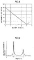
- Figure 9 exemplifies a frequency characteristic of the oscillation amplitude.
- variable speed motor If it is done in this way, in the variable speed motor, the oscillation and teh undesired sound can be reduced in the resonance frequency, furthermore, processing load of the control system is reduced by omitting control to correct the electromagnetic force drift in the non-resonance region, it becomes possible to utilize redundant throughput for other control processings.
- slot number n spp of the stator core 17 per every pole every phase of the stator 21, is "4".
- Phase belt of the stator winding 3 of three phase is 60 degree in the electrical angle.
- the winding slot number in this phase belt is equal to n spp and it is four.
- the harmonic component of the electromagnetic force has a periodicity of 180/n degree in the electrical angle.
- the periodicity arises in every phase belt. Accordingly, if the search coils 30a to 30d is provided on four stator winding slot in one phase belt, the harmonic component of the electromagnetic force necessary for the correction control processing can be grasped by a sufficient accuracy.
- This each search coil 30 (30a to 30d) is wound more than one turn so as to surround a teeth part 17c as hown in figure 11.
- Figure 12 shows a step for the signal processing to calculate the electromagnetic force based on a variation of the magnetic flux interlinkaged with the teeth part 17c.
- this induced voltage is in proportion to a time variation of the magnetic flux which interlinkages to each teeth part 17c
- the magnetic flux density can be obtained by integrating this induced voltage signal with the time. This integral can be obtained based on digital quantity or may be used an integrating circuit.
- the electromagnetic force in the diameter direction of the stator is in proportion to square of the magnetic flux density approximately in the diameter direction, the electromagnetic force can be calculated by operating the magnetic flux density signal into square.
- Electromagnetic force data of these each teeth part 17c are developed between space, and the harmonic component of the electromagnetic force is calculated by performing an electromagnetic force harmonic operation furthermore.
- the harmonic component of the electromagnetic force that the resonance mode and the frequency accord with a dc component is extracted. These signal processing is performed in an electromagnetic force oerating unit 40 shown in figure 13.
- the correction coefficient ⁇ (t) is generated from the correction coefficient generating circuitry 12, and the amplitude component of the activation current wave form flown in the stator winding 3 is corrected by means for multiplying it to the sign wave fundamental wave form.
- an element for detecting a mechanical drift can be used as an electromagnetic force drift detecting means.
- An acceleration sensor for detecting the oscillation around the stator core or a microphone for measuring the undesired sound is provided, thereby it becomes possible to take out the harmonic component of the electromagnetic force so as to process it, by a processing technique same as the electromagnetic signal processing as mentioned above.
- the electromagnetic force harmonic component can be calculated correcponding to aged deterioration of the electric motor and the load machine, there is an effect to reduce the oscillation and the undesired sound furthermore.
Landscapes
- Engineering & Computer Science (AREA)
- Power Engineering (AREA)
- Control Of Motors That Do Not Use Commutators (AREA)
- Motor Or Generator Frames (AREA)
- Control Of Electric Motors In General (AREA)
- Control Of Ac Motors In General (AREA)
Abstract
Description
- Present invention relates to a control device of a rotating electrical machinery and especially relates to the rotating electrical machinery which is improved so as to reduce electromagnetic oscillation in a diameter direction of a stator of a permanent magnet rotating electrical machinery and undesired sound caused by the electromagnetic oscillation. Permanent magnet rotating electrical machinery usually has a stator and a rotor.
- The stator has a stator core formed plural winding slots respectively keeping a same interval and a stator winding which is wound in the winding slot mentioned above.
- Magnetomotive force distribution of the stator winding is formed so as to superimpose a space harmonic wave on a sign wave (fundamental wave) and is varied in time in proportion to a stator winding current.
- Moreover in an inner diameter side of the stator, an opening part of the winding slot and a teeth part of the stator core are disposed alternately keeoing a same interval, and a magnetism permeance distribution of the stator becomes to containe ripplehaving a cycle made by the winding slot of the stator core
- Magnetic flux density of the magnetic field that the stator forms in the air gap is detemined by a product of a magnetomotive force distribution of this stator and a magnetism permeance of said stator, and this magnetic flux density contains a space harmonic component.
- Moreover, the rotor has a permanent magnet fixed by being inserted in a groove provided in the rotor core keeping a cirtain interval.
- Accordingly, a magnetic flux density of the magnetic field that the rotor provides in the air gap, contains the ripple in the same way and changes in time because being turned.
- As the magnetic flux density of the air gap is provided by composing the magnetic flux that the stator forms and the magnetic flux that the rotor forms, the magnetic flux density in this air gap is distributed so as to superimpose the harmonic component on the fundamental wave component, and changes in time.
- Because a torque acting on the rotor is an angle differentiation of a magnetic energy saved in the air gap, a ripple occurs to a torque generated by the ripple of the magnetic flux density of this air gap.
- This torque ripple sometimes causes a case as that a big oscillation in permanent magnet rotating electrical machinery and an undesired sound thereby appears.
- In order to reduce the ripple of the torque by controlling the stator winding current, a phase current correction means to correct so as to increase or decrease upto a maximum value of the sign wave within a range of ±30 degree of an electrical angle where magnitude of each phase current becomes maximum, and a control device of a synchronism motor prepared with a balancing means which let a total of the phase current balance are disclosed, for example, in Japanese Patent Laid-open No. 8-331884 and U.S.A. patent 4,240,020.
- By using these means, a method how to correct decreasing of the torque in a rotational direction occured in the transposition of the phase current is suggested.
- As a cause of the electromagnetic undesired Sound of the rotating electrical machinery, a circular ring oscillation of the stator may be pointed out besides the torque ripple in a rotational direction thereof.
- The electromagnetic force of the diameter direction acting on the stator causes the circular ring oscillation of this stator, and it is propagated to a stator frame of a stator periphery so as to vibrate said stator frame to the diameter direction and to generate the undesired sound.
- When space degree and frequency of the electromagnetic force harmonic component in the diameter direction, accords to resonance mode and frequency of the stator, the stator produces a resonance so as to occur a big undesired sound. Because the torque ripple is time variation of the electromagnetic force in a tangent direction, the conventional control device to reduce the torque ripple in the rotation direction which is performed up to now, cannot reduce the undesired sound caused by the magnetic force in the diameter direction.
- An object of the present invention is to reduce the oscillation generated by a drift of the electromagnetic force in the diameter direction of the stator in the rotating electrical machinery.
- In a control device of a rotating electrical machinery comprising, an inverter disposed between a stator winding and a direct current power supply of said rotating electrical machinery having a rotor formed a stator and the magnetic pole provided a stator winding on a stator core, an activation waveform generating circuit to occur an activation current wave form signal that met a magnetic pole position of said rotor, and a current control circuit to control the inverter so as to supply said activation electric current to the stator winding based on said activation current wave form signal and a stator winding current detecting signal, the present invention is characterised by comprising
- an electromagnetic force drift memory for memorizing a drift information of the electromagnetic force in diameter direction of the stator to act on the stator core having a stator winding thereon, and
- an activation waveform correction means to correct an amplitude of said activation current wave form signal based on an electromagnetic force drift information which is read from said electromagnetic force drift memory according to the magnetic pole position of the rotor.
-
- Futhermore, the present invention is characterised by comprising
- an electromagnetic force drift detecting means for detecting a drift of the electromagnetic force in a diameter direction of the stator to act on the stator core having a stator winding thereon,
- an electromagnetic force harmonic operation device to calculate an electromagnetic force harmonic component on the basis of a signal detected by said electromagnetic force drift detecting means,
- a correction information generating circuitry to occur a correction information to correct an electromagnetic force drift in the diameter direction of the stator by reading out the electromagnetic force harmonic component from the electromagnetic force harmonic operation device according to the magnetic pole position of the rotor, and
- an activation waveform correction means to correct the amplitude of the activation current wave form signal based on the correction information.
-
-
- Figure 1 is a circuitry block diagram of a control device of the permanent magnet rotating electrical machinery as the first embodiment of the present invention.
- Figure 2 is a vertical sectional view of the permanent magnet rotating electrical machinery in the first embodiment.
- Figure 3 is a vertical sectional front elevation view of the permanent magnet rotating electrical machinery shown to figure 2.
- Figure 4 is a view for showing a oscillation mode of space zero degree in the first embodiment.
- Figure 5 is a view to show an electromagnetic force harmonic component of the space zero degree in the first embodiment.
- Figure 6 is a view to show time change of electromagnetic force harmonic component in the first embodiment.
- Figure 7 shows a current wave form flowing through one phase of the stator winding in the first embodiment.
- Figure 8 is a characteristic figure showing change of the electromagnetic force for adjustment variables in the first embodiment.
- Figure 9 is a frequency characteristic figure of oscillation amplitude in the first embodiment.
- Figure 10 is a layout drawing of a search coil in the second embodiment of the present invention.
- Figure 11 is a view of a search coil winding in the second embodiment.
- Figure 12 is a block diagram showing a flow of signal processing in the second embodiment.
- Figure 13 is a circuitry block diagram of a control device of a permanent magnet rotating electrical machinery in the second embodiment.
-
- Referring to the drawings, the best mode of the embodiment to enforce the present invention will be explained as follows.
- Figure 1 is a circuitry block diagram of a control device of a permanent magnet rotating electrical machinery in the first embodiment of the present invention.
- Figure 2 is a vertical section side view of the permanent magnet rotating electrical machinery in this embodiment, and figure 3 is a vertical section front elevation of the above. In figure 2 and figure 3, reference numerall is a permanent magnet rotating electrical machinery, 2 a rotor, 21 a stator.
- The rotor 2 has a rotor core 19 that is provided around a shaft 20 and a permanent magnet 18 forming a magnetic pole around the rotor core 19.
- On the shaft 20 furthermore, a position sensor 6 to detect magnetic pole position of the rotor 2 and an encoder 7 to detect the rotating speed are installed. On the other hand, stator 21 has a stator core 17, a winding slot 17a formed in the stator core 17, a stator winding 3 wounded in this winding slot 17a so as to generate a rotational magnetic field, and a temperature sensor 22 to detect temperature of the stator core 17.
- Further, 17b is a yoke part of the stator core 17, and 17c is a teeth part.
- A control device for controlling this permanent magnet rotating electrical machinery 1 will be explained using figure 1 in the next.
- This control device prepares is provided a speed control function, and an example activated with a current wave form of a sign wave is explained.
- Most of a control system performing arithmetic processing is constituted so as to utilize a microcomputer, and the control processing function of the above is indicated as a control circuit here.
- An inverter 4 receives an initial power from a direct current power supply 5, and supplies a stator winding current (activation current) to a stator winding 3 of the permanent rotating electrical machinery 1.
- A position detecting circuit 14 obtains and outputs a position information based on a magnetic pole position detecting signal of the rotor 2 output from the position sensor 6 and a rotating speed detecting signal output from the encoder 7. The speed control circuitry (ASR) 16 inputs a velocity reference ωs and a real velocity ωf obtained by converting a position information from the position detecting circuit 14 with a F/V converter 15, calculates a difference
- The sign wave generating circuitry 10 generates a sign wave fundamental wave form (activation current wave form) signal Iav which is same-phase with an induced voltage of the stator winding 3 or is shifted the phase when needed, based on the position information output from the position sensor 6.
- The electromagnetic force drift memory 13 stores the drift information of the electromagnetic force to cause circular ring oscillation of the stator 21.
- Then, this electromagnetic force drift information begins to be read according to the position information , and it is supplied to a correction coefficient generating circuitry 12.
- The correction coefficient generating circuitry 12 generates a correction coefficient β(t) which seems to deny a drift of the electromagnetic force harmonic component as the main reason of the circular ring oscillation in a diameter idrection of the stator 21, that is, the amplitude component of the activation current.
- Here, t shows a time , and the correction coefficient varies with the time.
- Because, as the amount of the circular ring oscillation of the stator 21, is influenced by the temperature of the stator core 17, the correction coefficient generating circuitry 12 obtains the correction coefficient β(t) by adding the stator core temperature information Th detected by the temperature sensor 22.
- The multiplier 23 calculates a torque reference Tmod finished the correction by multiplying the correction coefficient β(t) into the mean torque reference Tav generated by the speed control circuitry (ASR) 16.
- The 2 phase -3 phase conversion circuitry 11 inputs the corrected torque reference Tmod and the sign wave fundamental wave form signal Iav and generates a current reference Isa, Isb, Isc for the activation current to flow to the winding of each phase of the stator winding 3.
- The phase current control circuit (ACR) 9a, 9b, 9c which controls current of each phase of the stator winding 3, controls the activation current of the each phase by supplying a control signal obtained proportional to the current reference Isa, Isb, Isc and the current detecting signal Ifa, Ifb, Ifc from the current detecting device 8a, 8b, 8c, to the inverter 4, thereby the rotational magnetic field that met to the rotation position of the rotor 2 is generated.
- Such drift of the electromagnetic force in the permanent magnet rotating electrical machinery 1 will be explained referring to figure 4 and figure 5.
- Figure 4 shows an oscillation mode of the stator 21 by the electromagnetic force harmonic of the zero space degree which occurs a big undesired sound with the lowest degree.
- The oscillation mode of the zero space degree means a mode in which a node or antinode of the oscillation does not exist.
- That is, in this oscillation mode, the stator 21 expands and contracts in a diameter direction uniformly. Figure 5 shows an electromagnetic force harmonic component of the zero space degree.
- In the next, a relationship of the stator winding current and the electromagnetic force in the diameter direction will be explained using figure 6 and figure 7.
- The value of the electromagnetic force in the diameter direction of the stator 21 can be obtained from a relative position of the rotor 2 for the stator 21 and the value of the stator winding current.
- Figure 7 shows a current wave form in one phase of the stator winding 3.
- In this embodiment, when the sign wave electric current is flowed in the stator winding 3, an electromagnetic force harmonic component of a time degree as shown to figure 5 occurs with the oscillation mode shown to figure 4.
- The biggest component is the zero time degree further. However, because the component of zero time degree is the dc component that does not depend to the time, it acts toward the center direction with the static force, accordingly, the component of the zero time degree does not make a contribution to the oscillation.
- In this embodiment, the sixth and the twelfth time degrees became a main component to generate the circular ring oscillation.
- When the frequency of the electromagnetic force harmonic accords to the resonance frequency in the oscillation mode of stator 21, the stator 21 does resonance so as to produce the big oscillation and occur the undesired sound.
- Here, an example in which the component of the twelfth time degree cxcitates the resonance, will be explained.
- However, the fundamental frequency of the activation current wave form is treated as a standard of the time degree.
- In figure 6, the electromagnetic force drift is shown in a case that DC component of the electromagnetic force harmonic component (component of the zero time degree) and the oscillation of the electromagnetic force in the twelfth time degree are added together by considering the phase.
- This electromagnetic force drift can be expressed in the next equation (1).
- Here, F 0,0 and F 0,12 respectively means amplitudes of the electromagnetic force harmonic components respectively in the zero space degree and the zero time degree, and the zero space degree and the twelfth time degree.
- The code α0,12 means the phase of the electromagnetic force harmonic component in the zero space degree and the twelfth time degree.
- These amplitude and phase can be demanded by an experiment or a harmonic analysis of the numerical analysis.
- The activation current wave form of the stator winding 3 becomes a sign wave fundamental wave form to show it in figure 7.
- The electromagnetic force harmonic component in the zero space degree and the zero time degree, and the zero space degree and the twelfth time degree is varied with the activation current of the stator winding 3.
- In the electromagnetic force drift shown in figure 6, when electromagnetic exciting force is big, the torque reference is made to be small, and on the contrary, when the electromagnetic exciting force is small, the torque reference is made to be big, thereby, the electromagnetic force is controlled to be constant and the oscillation and the undesired sound can be reduced.
- An example to make the electromagnetic force F 0,0 as the constant value will be explained.
- First of all, the correction coefficient β(t) which seems to be satisfied with the next equation (2) is obtained.
- By forming current references Isa, Isb, Isc which transformes the sign wave fundamental wave form (signal Iav) with the correction coefficient β(t), the amplitude of the activation current is controlled as a waveform which is corrected as shown in figure 7, thereby, the drift of the electromagnetic force in the diameter direction of stator by time degree the twelfth component is suppressed, and the electromagnetic force may be kept to be F 0,0.
- Here, the correction coefficient β(t) can be expressed in the next equation (3).

- Here, because F 0,12 is fully small comparing it with F 0,0 and a next equation (4) is provided.
- Practically, because of an affection of a magnetic saturation of the core of the stator 21 and the rotor 2, the equation (4) is not corrected enough.
- Therefore, it is desirable to use an adjustment variables γ which are variables considering affection of the magnetic saturation further to the correction coefficient β(t).
- Then the correction coefficient β(t) may be expressed in the following equation (5).
- By using the adjustment variables γ as a parameter, the electromagnetic force harmonic component of the twelfth degree mentioned above is calculated, and the variation of the electromagnetic force harmonic component for this adjustment variables γ is shown in figure 8.
- When the djustment variables γ are zero, a condition as that any correction is not made on at all is shown.
- In this embodiment, the case of γ =4 can reduces a ratio of the electromagnetic force to be 1 % in comparison with the case of γ =0 (100 %).
- Accordingly, the oscillation and the undesired sound to originate in this electromagnetic force harmonic component becomes possible to be reduced largely.
- In an electromagnetic force drift memory 13, a resonance frequency to be provided by an electromagnetic analysis or an experiment, the electromagnetic force harmonic component which should be reduced, the time degree, the amplitude, and the phase of the harmonic component of the current, and the adjustment variables, are stored by a form such as a table etc.
- In the permanent magnet rotating electrical machinery which is prepared with a stator winding of n phase, the harmonic component of the electromagnetic force has periodicity of 180/n degree in electrical angle.
- Accordingly, if the data of the electromagnetic force harmonic are stored relating to a current-carrying section of 180/n degree in the electrical angle, they are read out repeatedly and are used to correct it in all section.
- According to the present embodiment, it has an effect as that the oscillation by the circular ring oscillation of the stator 21 and the undesired sound thereby may be reduced.
- Moreover, the embodiment using the twelfth time degree is described as above, however, the oscillation and undesired sound in other time degrees, can be reduced in the same way.
- Moreover, the correction coefficient β(t) is multiplyed with a mean torque reference value Tav by a multiplier 23 so as to correct the amplitude component of the activation current, thereby to obtain a corrected torque reference Tmod, however, the corrected torque reference Tmod may be obtain by adding the correction component being equivalent to the multiplication to the mean torque reference value Tav.
- Moreover, in figure 1, the correction signal from the correction coefficient generating circuitry 12 is added to the mean torque reference Tav so that the amplitude component of the activation current is corrected indirectly, however the correction signal from this correction coefficient generating circuitry 12 may be added directly to a two phase-three phase conversion circuitry 11, thereby the activation current is corrected as shown in figure 7.
- As an example applied this embodiment next, a case applied to a variable speed motor will be explained.
- Figure 9 exemplifies a frequency characteristic of the oscillation amplitude.
- In this example, plural resonance frequencies f1, f2 exist in the motor.
- When a revolutional speed of the motor is changed and the frequency of the electromagnetic force harmonic component becomes to be close to the resonance frequency f1, f2, the correction function means mentioned above is operated, and when it is driven with an other frequency domain, the correction function means is stopped.
- If it is done in this way, in the variable speed motor, the oscillation and teh undesired sound can be reduced in the resonance frequency, furthermore, processing load of the control system is reduced by omitting control to correct the electromagnetic force drift in the non-resonance region, it becomes possible to to utilize redundant throughput for other control processings.
- In next, as a second embodiment of the present invention, an example of a permanent magnet rotating electrical machinery of three phase four pole will be explained.
- Figure 10 shows a vertical sectional front view of the stator core of the three phase four pole permanent magnet rotating electrical machinery.
- In this embodiment, slot number n spp of the stator core 17 per every pole every phase of the stator 21, is "4". Phase belt of the stator winding 3 of three phase is 60 degree in the electrical angle.
- The winding slot number in this phase belt is equal to n spp and it is four.
- Moreover, as mentioned above, the harmonic component of the electromagnetic force has a periodicity of 180/n degree in the electrical angle.
- That is, the periodicity arises in every phase belt. Accordingly, if the search coils 30a to 30d is provided on four stator winding slot in one phase belt, the harmonic component of the electromagnetic force necessary for the correction control processing can be grasped by a sufficient accuracy.
- This each search coil 30 (30a to 30d) is wound more than one turn so as to surround a teeth part 17c as hown in figure 11.
- Figure 12 shows a step for the signal processing to calculate the electromagnetic force based on a variation of the magnetic flux interlinkaged with the teeth part 17c.
- Moreover, a circuitry block of the control device corresponding to this signal processing is shown to figure 13.
- Relating to the permanent magnet rotating electrical machinery and the control device thereof shown to figure 13, an equal or equivalent component part with the embodiment shown in figure 1, is omitted to be described repeatly by attaching the same reference code.
- Refering to the rotation position information signal and by using a signal of one set point as a trigger, an induced voltage of the search coil 30a to 30d of each teeth part 17c is measured.
- Because this induced voltage is in proportion to a time variation of the magnetic flux which interlinkages to each teeth part 17c, the magnetic flux density can be obtained by integrating this induced voltage signal with the time. This integral can be obtained based on digital quantity or may be used an integrating circuit.
- Because the electromagnetic force in the diameter direction of the stator is in proportion to square of the magnetic flux density approximately in the diameter direction, the electromagnetic force can be calculated by operating the magnetic flux density signal into square.
- Electromagnetic force data of these each teeth part 17c are developed between space, and the harmonic component of the electromagnetic force is calculated by performing an electromagnetic force harmonic operation furthermore.
- The harmonic component of the electromagnetic force that the resonance mode and the frequency accord with a dc component is extracted. These signal processing is performed in an electromagnetic force oerating unit 40 shown in figure 13.
- Based on this operation result, the correction coefficient β(t) is generated from the correction coefficient generating circuitry 12, and the amplitude component of the activation current wave form flown in the stator winding 3 is corrected by means for multiplying it to the sign wave fundamental wave form.
- Further, in this embodiment, an element for detecting a mechanical drift can be used as an electromagnetic force drift detecting means.
- An acceleration sensor for detecting the oscillation around the stator core or a microphone for measuring the undesired sound is provided, thereby it becomes possible to take out the harmonic component of the electromagnetic force so as to process it, by a processing technique same as the electromagnetic signal processing as mentioned above.
- According to this embodiment, because the electromagnetic force harmonic component can be calculated correcponding to aged deterioration of the electric motor and the load machine, there is an effect to reduce the oscillation and the undesired sound furthermore.
- According to the present invention as stated above, there is a remarkable effect as that the oscillation of the diameter direction generated by the electromagnetic force of the rotating electrical machinery can be reduced, and the undesired sound to originate in this oscillation is reduced.
Claims (8)
- A control device for a rotating electrical machinery having a stator that put stator winding for stator core and a rotor formed a magnetic pole thereon, comprising an inverter provided among said stator winding and a direct current power supply, an activation waveform generating circuitry for generating an activation current wave form signal corresponding to a magnetic pole position of said rotor, and a current control circuit for controlling said inverter so as to flow an activation current into said stator winding based on said activation current wave form signal and a detecting signal to detect a current flown in said stator windin, said control device further comprisingan electromagnetic force drift memory for storing drift information of said electromagnetic force in a diameter direction of said stator acting on said stator core having said stator winding, andan activation waveform correction means for correcting an amplitude of said activation current wave form signal based on an electromagnetic force drift information read from said electromagnetic force drift memory according to said magnetic pole position of said rotor.
- A control device for a rotating electrical machinery having a stator that put stator winding for stator core and a rotor formed a magnetic pole thereon, comprising an inverter provided among said stator winding and a direct current power supply, an activation waveform generating circuitry for generating an activation current wave form signal corresponding to a magnetic pole position of said rotor, and a current control circuit for controlling said inverter so as to flow an activation current into said stator winding based on said activation current wave form signal and a detecting signal to detect a current flown in said stator windin, said control device further comprisingan electromagnetic force drift detecting means for detecting a drift of the electromagnetic force in a diameter direction of the stator to act on the stator core having a stator winding thereon,an electromagnetic force harmonic operation device to calculate an electromagnetic force harmonic component on the basis of a signal detected by said electromagnetic force drift detecting means,a correction information generating circuitry to occur a correction information to correct an electromagnetic force drift in the diameter direction of the stator by reading out the electromagnetic force harmonic component from the electromagnetic force harmonic operation device according to the magnetic pole position of the rotor, andan activation waveform correction means to correct the amplitude of the activation current wave form signal based on the correction information.
- A control device for a rotating electrical machinery as defined in claim 1 or 2, whereinsaid activation current wave form is a sign wave.
- A control device for a rotating electrical machinery as defined in one of claims 1 to 3, whereina space degree of harmonic component of said electromagnetic force is zero.
- 4. A control device for a rotating electrical machinery as defined in one of claims 1, 3 to 4, whereinsaid rotating electrical machinery has a stator winding of n phase, anda section to store said harmonic component of said electromagnetic force is180/ n in an electrical angle.
- A control device for a rotating electrical machinery as defined in one of claims 2 to 5, whereinsaid electromagnetic force drift detecting means is one of an electric signal detection element, an oscillation detecting elementand an undesired sound measurement element.
- A control device for a rotating electrical machinery as defined in one of claims 1 to 6, whereincorrection of said activation current wave form is performed by limitting within a resonance region.
- A control device for a rotating electrical machinery as defined in one of claims 1 to 7, whereina correction characteristic of said activation current wave form is changed according to temperature of said rotating electrical machinery.
Applications Claiming Priority (3)
| Application Number | Priority Date | Filing Date | Title |
|---|---|---|---|
| JP14994198 | 1998-05-29 | ||
| JP14994198A JP3366858B2 (en) | 1998-05-29 | 1998-05-29 | Control device for rotating electric machine |
| PCT/JP1999/002635 WO1999063654A1 (en) | 1998-05-29 | 1999-05-19 | Motor control device |
Publications (3)
| Publication Number | Publication Date |
|---|---|
| EP1087517A1 true EP1087517A1 (en) | 2001-03-28 |
| EP1087517A4 EP1087517A4 (en) | 2003-06-04 |
| EP1087517B1 EP1087517B1 (en) | 2006-03-01 |
Family
ID=15485926
Family Applications (1)
| Application Number | Title | Priority Date | Filing Date |
|---|---|---|---|
| EP99921192A Expired - Lifetime EP1087517B1 (en) | 1998-05-29 | 1999-05-19 | Motor control device |
Country Status (5)
| Country | Link |
|---|---|
| US (1) | US6404152B1 (en) |
| EP (1) | EP1087517B1 (en) |
| JP (1) | JP3366858B2 (en) |
| DE (1) | DE69930114T2 (en) |
| WO (1) | WO1999063654A1 (en) |
Cited By (4)
| Publication number | Priority date | Publication date | Assignee | Title |
|---|---|---|---|---|
| EP1211798A3 (en) * | 2000-11-22 | 2002-09-25 | Nissan Motor Co., Ltd. | Motor control apparatus and motor control method |
| EP1292011A2 (en) * | 2001-09-10 | 2003-03-12 | Nissan Motor Co., Ltd. | Motor control for reducing high harmonic currents |
| WO2004055967A1 (en) * | 2002-10-17 | 2004-07-01 | Denso Corporation | Ac rotary electric machine magnetic noise reduction method, motor control device and ac rotary electric machine using the same |
| DE102004001932A1 (en) * | 2004-01-14 | 2005-08-11 | Minebea Co., Ltd. | Method for controlling an electronically commutated motor and motor control |
Families Citing this family (23)
| Publication number | Priority date | Publication date | Assignee | Title |
|---|---|---|---|---|
| JP3499786B2 (en) * | 1999-11-25 | 2004-02-23 | 株式会社日立製作所 | Ultra-high-speed permanent magnet rotating electric machine system |
| US6774592B2 (en) * | 2001-12-03 | 2004-08-10 | Delphi Technologies, Inc. | Method and system for controlling a permanent magnet machine |
| JP3721368B2 (en) * | 2003-05-23 | 2005-11-30 | ファナック株式会社 | Motor control device |
| JP4239886B2 (en) * | 2004-04-14 | 2009-03-18 | 株式会社デンソー | Magnetic sound control method for AC rotating electric machine |
| JP2005304237A (en) | 2004-04-14 | 2005-10-27 | Denso Corp | Magnetic sound control method of ac rotary electric machine |
| JP2007043889A (en) * | 2005-06-27 | 2007-02-15 | Denso Corp | Motor controller |
| JP2007295672A (en) * | 2006-04-21 | 2007-11-08 | Denso Corp | Motor control device |
| CN100461615C (en) * | 2005-06-27 | 2009-02-11 | 株式会社电装 | Motor control apparatus |
| DE102006028331B4 (en) * | 2005-06-27 | 2019-02-14 | Denso Corporation | Motor controller |
| JP4789720B2 (en) | 2006-07-07 | 2011-10-12 | 三洋電機株式会社 | Motor control device |
| US8183814B2 (en) | 2008-07-24 | 2012-05-22 | Ewald Franz Fuchs | Alternating current machine with increased torque above and below rated speed for hybrid electric propulsion systems |
| JP2012115044A (en) * | 2010-11-25 | 2012-06-14 | Okuma Corp | Magnetic pole position correction method for motor |
| JP5703956B2 (en) * | 2011-05-18 | 2015-04-22 | 株式会社デンソー | Rotating machine control device and manufacturing method thereof |
| US8344669B1 (en) * | 2012-04-02 | 2013-01-01 | Etagen, Inc. | Methods and systems for controlling a multiphase electromagnetic machine |
| JP5648654B2 (en) * | 2012-04-23 | 2015-01-07 | 株式会社デンソー | Rotating machine control device |
| CN204068791U (en) * | 2014-03-25 | 2014-12-31 | 睿能机电有限公司 | A kind of electromagnetic torque pulsation suppression device of brshless DC motor |
| JP6459878B2 (en) * | 2015-09-28 | 2019-01-30 | 株式会社デンソー | Control device for rotating electrical machine |
| JP6485330B2 (en) * | 2015-11-10 | 2019-03-20 | 株式会社デンソー | Motor control device |
| DE102017101866B4 (en) | 2016-02-01 | 2022-06-02 | Denso Corporation | Control device for a rotating electrical machine |
| JP6841018B2 (en) * | 2016-02-01 | 2021-03-10 | 株式会社デンソー | Rotating machine control device |
| JP6833077B2 (en) * | 2018-02-08 | 2021-02-24 | 三菱電機株式会社 | Control device for multi-group multi-phase rotary machine and drive device for multi-group multi-phase rotary machine |
| US10637386B2 (en) * | 2018-07-26 | 2020-04-28 | Enedym Inc. | Torque ripple reduction in switched reluctance machine |
| JP7323329B2 (en) * | 2019-05-13 | 2023-08-08 | 日立Astemo株式会社 | Motor control device, electric power steering system, electric brake system, electric vehicle system |
Citations (2)
| Publication number | Priority date | Publication date | Assignee | Title |
|---|---|---|---|---|
| US5298841A (en) * | 1990-04-18 | 1994-03-29 | Hitachi, Ltd. | Apparatus for controlling the speed of a moving object |
| JPH1094217A (en) * | 1996-09-12 | 1998-04-10 | Ebara Corp | Control system for permanent magnet rotating electric machine generating radial force |
Family Cites Families (12)
| Publication number | Priority date | Publication date | Assignee | Title |
|---|---|---|---|---|
| US4088934A (en) * | 1976-10-04 | 1978-05-09 | General Electric Company | Means for stabilizing an a-c electric motor drive system |
| JPS5413919A (en) | 1977-07-04 | 1979-02-01 | Hitachi Ltd | Preventive controller for torque pulsation |
| US4724373A (en) * | 1986-02-20 | 1988-02-09 | Wisconsin Alumni Research Foundation | Method and apparatus for flux and torque sensing in electrical machines |
| JPH01318579A (en) * | 1988-06-16 | 1989-12-25 | Secoh Giken Inc | Reluctance type therr-phase motor |
| JPH02106192A (en) * | 1988-10-13 | 1990-04-18 | Secoh Giken Inc | Reluctance motor |
| JPH0817585B2 (en) * | 1989-02-06 | 1996-02-21 | 株式会社日立製作所 | Torque control device |
| US5334923A (en) * | 1990-10-01 | 1994-08-02 | Wisconsin Alumni Research Foundation | Motor torque control method and apparatus |
| US5134349A (en) * | 1991-05-28 | 1992-07-28 | Kruse David L | Two-phase brushless dc motor controller |
| JPH06327285A (en) * | 1993-05-17 | 1994-11-25 | Matsushita Electric Ind Co Ltd | Motor speed controller |
| KR950015957A (en) * | 1993-11-12 | 1995-06-17 | 이대원 | Vector control method and apparatus of induction motor |
| JP3137560B2 (en) | 1995-05-29 | 2001-02-26 | トヨタ自動車株式会社 | Synchronous motor controller |
| JPH10234196A (en) * | 1997-02-19 | 1998-09-02 | Toshiba Corp | Device for drive brushless motor |
-
1998
- 1998-05-29 JP JP14994198A patent/JP3366858B2/en not_active Expired - Lifetime
-
1999
- 1999-05-19 EP EP99921192A patent/EP1087517B1/en not_active Expired - Lifetime
- 1999-05-19 US US09/463,654 patent/US6404152B1/en not_active Expired - Fee Related
- 1999-05-19 DE DE69930114T patent/DE69930114T2/en not_active Expired - Fee Related
- 1999-05-19 WO PCT/JP1999/002635 patent/WO1999063654A1/en active IP Right Grant
Patent Citations (2)
| Publication number | Priority date | Publication date | Assignee | Title |
|---|---|---|---|---|
| US5298841A (en) * | 1990-04-18 | 1994-03-29 | Hitachi, Ltd. | Apparatus for controlling the speed of a moving object |
| JPH1094217A (en) * | 1996-09-12 | 1998-04-10 | Ebara Corp | Control system for permanent magnet rotating electric machine generating radial force |
Non-Patent Citations (3)
| Title |
|---|
| PATENT ABSTRACTS OF JAPAN vol. 1998, no. 09, 31 July 1998 (1998-07-31) & JP 10 094217 A (EBARA CORP;FUKAO TADASHI; CHIBA AKIRA), 10 April 1998 (1998-04-10) * |
| See also references of WO9963654A1 * |
| VERMA S P ET AL: "Electromagnetic acoustic noise and vibrations of synchronous machines: the problems, causes and reduction" ICEMA. INTERNATIONAL CONFERENCE ON ELECTRICAL MACHINES IN AUSTRALIA PROCEEDINGS, INTERNATIONAL CONFERENCE ON ELECTRICAL MACHINES IN AUSTRALIA, ADELAIDE, SA, AUSTRALIA, 14-16 SEPT. 1993, pages 199-204 vol.1, XP002225127 1993, The Levels, SA, Australia, Univ. South Australia, Australia * |
Cited By (8)
| Publication number | Priority date | Publication date | Assignee | Title |
|---|---|---|---|---|
| EP1211798A3 (en) * | 2000-11-22 | 2002-09-25 | Nissan Motor Co., Ltd. | Motor control apparatus and motor control method |
| US6674262B2 (en) | 2000-11-22 | 2004-01-06 | Nissan Motor Co., Ltd. | Motor control apparatus and motor control method |
| EP1292011A2 (en) * | 2001-09-10 | 2003-03-12 | Nissan Motor Co., Ltd. | Motor control for reducing high harmonic currents |
| EP1292011A3 (en) * | 2001-09-10 | 2005-02-02 | Nissan Motor Co., Ltd. | Motor control for reducing high harmonic currents |
| WO2004055967A1 (en) * | 2002-10-17 | 2004-07-01 | Denso Corporation | Ac rotary electric machine magnetic noise reduction method, motor control device and ac rotary electric machine using the same |
| US7151354B2 (en) | 2002-10-17 | 2006-12-19 | Denso Corporation | Magnetic noise reduction method for AC rotary electric machine, and motor control apparatus and AC rotary electric machine apparatus using the same |
| DE102004001932A1 (en) * | 2004-01-14 | 2005-08-11 | Minebea Co., Ltd. | Method for controlling an electronically commutated motor and motor control |
| DE102004001932B4 (en) * | 2004-01-14 | 2009-10-01 | Minebea Co., Ltd. | Method for controlling an electronically commutated motor and motor control |
Also Published As
| Publication number | Publication date |
|---|---|
| WO1999063654A8 (en) | 2000-02-10 |
| JP3366858B2 (en) | 2003-01-14 |
| DE69930114T2 (en) | 2006-09-28 |
| DE69930114D1 (en) | 2006-04-27 |
| US6404152B1 (en) | 2002-06-11 |
| JPH11341864A (en) | 1999-12-10 |
| EP1087517A4 (en) | 2003-06-04 |
| WO1999063654A1 (en) | 1999-12-09 |
| EP1087517B1 (en) | 2006-03-01 |
Similar Documents
| Publication | Publication Date | Title |
|---|---|---|
| EP1087517A1 (en) | Motor control device | |
| EP0768750B1 (en) | Switched-reluctance rotary machine | |
| EP0895344B1 (en) | A method of controlling a torque ripple of a motor having interior permanent magnets and a controller using the same method | |
| US5691613A (en) | Method for determining a rotor position of a rotary motor or linear motor, and circuit arrangement for carrying out the method | |
| JP4364871B2 (en) | Phase advance angle optimization for brushless motor control | |
| US6650083B2 (en) | Speed control apparatus of synchronous reluctance motor and method thereof | |
| KR20010066851A (en) | Active reduction of torque irregularities in rotating machines | |
| Hurst et al. | Speed sensorless field-oriented control of induction machines using current harmonic spectral estimation | |
| EP0756778A1 (en) | Method and apparatus for controlling induction motors | |
| EP2988411A1 (en) | Motor drive control apparatus and motor drive control method | |
| US20090261765A1 (en) | Synchronous motor, encoderless motor system and a method for operating an encoderless motor system with a synchronous motor | |
| JP5795980B2 (en) | Electric motor control device | |
| US8664902B2 (en) | Polyphase AC motor, driving device and driving method therefor | |
| US5847535A (en) | Active electronic damping for step motor | |
| JPH1155986A (en) | Controller for permanent magnet electric rotating machine | |
| JP4117554B2 (en) | Motor control device | |
| US5886493A (en) | Synchronous machine excitation control device for absorbing harmonics superposed onto fundamental current | |
| Langheck et al. | NVH optimization in PMSM through harmonic current injection with optimum current trajectory | |
| Antonello et al. | Torque ripple minimization in hybrid stepper motors using acceleration measurements | |
| US6229277B1 (en) | Method and apparatus for the damping of motor vibrations | |
| JPH08331884A (en) | Synchronous motor controller | |
| JPH03245755A (en) | Brushless self-excitation synchronous electric motor | |
| JPH0716000A (en) | Unbalanced load compensation power generating system | |
| JP2012050192A (en) | Motor drive controller | |
| EP4148973A1 (en) | Motor control device |
Legal Events
| Date | Code | Title | Description |
|---|---|---|---|
| PUAI | Public reference made under article 153(3) epc to a published international application that has entered the european phase |
Free format text: ORIGINAL CODE: 0009012 |
|
| 17P | Request for examination filed |
Effective date: 20000707 |
|
| AK | Designated contracting states |
Kind code of ref document: A1 Designated state(s): DE FR GB IT |
|
| A4 | Supplementary search report drawn up and despatched |
Effective date: 20030425 |
|
| 17Q | First examination report despatched |
Effective date: 20031031 |
|
| GRAP | Despatch of communication of intention to grant a patent |
Free format text: ORIGINAL CODE: EPIDOSNIGR1 |
|
| GRAS | Grant fee paid |
Free format text: ORIGINAL CODE: EPIDOSNIGR3 |
|
| GRAA | (expected) grant |
Free format text: ORIGINAL CODE: 0009210 |
|
| RAP1 | Party data changed (applicant data changed or rights of an application transferred) |
Owner name: HITACHI, LTD. |
|
| AK | Designated contracting states |
Kind code of ref document: B1 Designated state(s): DE FR GB IT |
|
| REG | Reference to a national code |
Ref country code: GB Ref legal event code: FG4D |
|
| REF | Corresponds to: |
Ref document number: 69930114 Country of ref document: DE Date of ref document: 20060427 Kind code of ref document: P |
|
| ET | Fr: translation filed | ||
| PLBE | No opposition filed within time limit |
Free format text: ORIGINAL CODE: 0009261 |
|
| STAA | Information on the status of an ep patent application or granted ep patent |
Free format text: STATUS: NO OPPOSITION FILED WITHIN TIME LIMIT |
|
| 26N | No opposition filed |
Effective date: 20061204 |
|
| PGFP | Annual fee paid to national office [announced via postgrant information from national office to epo] |
Ref country code: DE Payment date: 20080606 Year of fee payment: 10 |
|
| PGFP | Annual fee paid to national office [announced via postgrant information from national office to epo] |
Ref country code: IT Payment date: 20080423 Year of fee payment: 10 |
|
| PGFP | Annual fee paid to national office [announced via postgrant information from national office to epo] |
Ref country code: GB Payment date: 20080424 Year of fee payment: 10 |
|
| GBPC | Gb: european patent ceased through non-payment of renewal fee |
Effective date: 20090519 |
|
| REG | Reference to a national code |
Ref country code: FR Ref legal event code: ST Effective date: 20100129 |
|
| PG25 | Lapsed in a contracting state [announced via postgrant information from national office to epo] |
Ref country code: FR Free format text: LAPSE BECAUSE OF NON-PAYMENT OF DUE FEES Effective date: 20090602 |
|
| PGFP | Annual fee paid to national office [announced via postgrant information from national office to epo] |
Ref country code: FR Payment date: 20080423 Year of fee payment: 10 |
|
| PG25 | Lapsed in a contracting state [announced via postgrant information from national office to epo] |
Ref country code: GB Free format text: LAPSE BECAUSE OF NON-PAYMENT OF DUE FEES Effective date: 20090519 |
|
| PG25 | Lapsed in a contracting state [announced via postgrant information from national office to epo] |
Ref country code: DE Free format text: LAPSE BECAUSE OF NON-PAYMENT OF DUE FEES Effective date: 20091201 |
|
| PG25 | Lapsed in a contracting state [announced via postgrant information from national office to epo] |
Ref country code: IT Free format text: LAPSE BECAUSE OF NON-PAYMENT OF DUE FEES Effective date: 20090519 |