EP1087146A2 - Impeller for fan, fan using the same, and air conditioner using the same - Google Patents
Impeller for fan, fan using the same, and air conditioner using the same Download PDFInfo
- Publication number
- EP1087146A2 EP1087146A2 EP00119461A EP00119461A EP1087146A2 EP 1087146 A2 EP1087146 A2 EP 1087146A2 EP 00119461 A EP00119461 A EP 00119461A EP 00119461 A EP00119461 A EP 00119461A EP 1087146 A2 EP1087146 A2 EP 1087146A2
- Authority
- EP
- European Patent Office
- Prior art keywords
- blade
- impeller
- hub
- fan
- representative
- Prior art date
- Legal status (The legal status is an assumption and is not a legal conclusion. Google has not performed a legal analysis and makes no representation as to the accuracy of the status listed.)
- Granted
Links
Images


Classifications
-
- F—MECHANICAL ENGINEERING; LIGHTING; HEATING; WEAPONS; BLASTING
- F04—POSITIVE - DISPLACEMENT MACHINES FOR LIQUIDS; PUMPS FOR LIQUIDS OR ELASTIC FLUIDS
- F04D—NON-POSITIVE-DISPLACEMENT PUMPS
- F04D29/00—Details, component parts, or accessories
- F04D29/26—Rotors specially for elastic fluids
- F04D29/32—Rotors specially for elastic fluids for axial flow pumps
- F04D29/38—Blades
- F04D29/384—Blades characterised by form
Definitions
- the present invention relates to an impeller used in a fan, a fan using the impeller, and an air conditioner using the same.
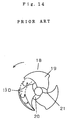
- FIG. 15 A plan of an impeller of a conventional mixed flow fan is shown in Fig. 15, and a rotation locus diagram of the impeller is given in Fig. 15.
- the gas flows in the impeller in inclination toward the rotary shaft.
- the impeller 18 of the mixed flow fan comprises a truncated conical hub 20, and a plurality of blades 19 disposed in the hub 20.
- the rotation locus of the impeller 18 is shown in Fig. 14.
- the fan comprises this impeller 18, a casing accommodating the impeller 18, a rotary shaft coupled to the hub 20, and a motor. As the impeller 18 is rotated by the motor, a blowing action takes place.
- the aspect ratio b/L or the ratio of the chord length L of the blade at the representative square mean radius position of the vanes 19 and the representative actual length b in the radial direction of the blades is 1 or less, that is, in a range of b/L ⁇ 1 , the number of blades 19 required for obtaining a sufficient static pressure is at least three or more.
- the front edge 21 of the blades 19 has a logarithmic spiral or similar curve.
- a blade end vortex 19D occurs in the arrow direction near the outer circumference of the rotating blades 19.
- the blade end vortex 19D was separated from the blade 19, and had a large effect on the influent air state of the succeeding blade 19. That is, the succeeding blade 19 had a large effect on the blade end vortex 19D generated and separated from the preceding vane, and the succeeding blade 19 worked pneumatically while receiving a largely disturbed influent air. Therefore, due to the effects of the blade end vortex 19D, there was a limit in reduction of noise and improvement of static pressure characteristic.
- the impeller for fan of the invention comprises a hub, and two blades disposed in the hub, in which each blade has a shape with an aspect ratio (b/L) defined in a range of b/L ⁇ 1 where "L” is the chord length of the blade at a representative square mean radius position of each blade of the two blades and "b" is the representative actual length in the radial direction of each blade.
- the two blades are disposed symmetrically to the center of the hub.
- the fan of the invention comprises a motor, and an impeller connected to the motor, in which the impeller has the same fan as the above impeller.
- the air conditioner of the invention comprises an indoor unit, an outdoor unit, and a piping installed between the indoor unit and outdoor unit, in which the outdoor unit has a heat exchanger and a fan, the fan has a motor and an impeller connected to the motor, and the impeller has the same fan as the above impeller.
- the impeller having two blades is smaller in volume than the impeller having three or more blades, so that the manufacturing cost of the impeller is lowered.
- the impeller for fan in an embodiment of the invention comprises a hub, and two blades disposed in the hub, in which each blade has a shape with an aspect ratio (b/L) defined in a range of b/L ⁇ 1 where "L” is the chord length of the blade at a representative square mean radius position of each blade of the two blades and "b" is the representative actual length in the radial direction of each blade.
- the individual blades are mutually disposed symmetrically to the center of the hub.
- the impeller having two blades has a smaller volume than the impeller having three blades or four blades.
- the portion from around the representative square mean radius position of the blade to the position at the outer circumference has a concave curve shape to the windward side
- the portion from around the representative square mean radius position of the blade to the position at the hub side has a convex curve shape to the windward side.
- the blade since the blade has a concave curve shape, the blade itself becomes a stream-line body in the rotating direction of the blade. Therefore, in the case of two blades, the blade rotating noise or "nZ" sound becomes lower than the sound pressure level of the turbulent flow noise. As a result, generation of abnormal sound in the entire impeller is prevented. Further, actual auditory sense is improved.
- one point of triangular auxiliary blade is overlapped on the intersection of the front edge of the blade and the outer circumference, and one side of the triangular auxiliary blade is formed in tight contact with the front edge.
- the triangular auxiliary vane is disposed in the blade as the principal blade.
- the blade end vortex is generated conically on the negative pressure surface of the blade, and this blade end vortex is separated and flows away in the midst of the blade.
- the triangular vane has an action of defining the generation of blade end vortex at its leading end. Accordingly, the triangular blade defines the state of generation of the blade end vortex on the negative pressure surface near the outer circumference of the blade, and the state of the blade end vortex separating from the blade and flowing away. Therefore the triangular blade has an action of minimizing the effect of the blade end vortex on the blade rotating behind.
- the influent air state of the blade rotating behind can be kept in the smooth and optimum state having a further smaller turbulent flow.
- the succeeding blade is less influenced by the effect of the blade end vortex, and the influent air into the blade is most smooth, and separation, decline of speed and other unstable phenomena in the succeeding blades are less likely to occur.
- the fan having such impeller is installed in the outdoor unit of the air conditioner having a heat exchanger.
- the outdoor unit operates quietly. Further, the manufacturing cost is low. The design is easier and it is more advantageous.
- Fig. 1 to Fig. 9 show the impeller for fan of an exemplary embodiment of the invention.
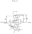
- Fig. 1 is a rotation locus diagram of impeller used in a mixed flow blower.
- Fig. 2 is a plan of the impeller for the mixed flow fan.
- Fig. 3 is a development by cutting off the impeller for the fan at a representative square mean radius position, and developing it. In Fig. 3, the blade is a thick blade.
- Fig. 4 is a development by cutting off the impeller for the fan at a representative square mean radius position, and developing it, in which a thin blade of a specific thickness is applied as the blade.
- Fig. 5 is a schematic diagram showing an operating status of the impeller used in the fan.
- Fig. 1 is a rotation locus diagram of impeller used in a mixed flow blower.
- Fig. 2 is a plan of the impeller for the mixed flow fan.
- Fig. 3 is a development by cutting off the impeller for the fan at a
- FIG. 6 is a characteristic diagram of characteristic experiment showing the performance of the impeller for the fan, in which the axis of abscissas denotes the aspect ratio b/L, and the axis of ordinates represents the air flow volume at blowing noise 41 dB.
- Fig. 7 is a characteristic diagram comparing the static pressure characteristics between an impeller for fan having two blades in the exemplary embodiment of the invention, and an impeller for fan having three blades in a prior art.
- Fig. 8 is a rotation locus diagram of the impeller for fan when used in an axial flow fan.
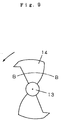
- Fig. 9 is a plan of the impeller for the axial flow fan.
- the impeller 1 used in the mixed flow fan comprises a truncated conical hub 3, and two blades 2 disposed on the outer circumference of the hub 3.
- the two blades 2 mutually have an identical shape, and the blades 2 are installed at mutually facing positions. That is, the blades 2 are disposed at mutually symmetrical positions to the center of the hub 3.
- the blades 2 are defined by the aspect ratio b/L where L is the chord length of the blade at the representative square mean radius position of the blade and b is the representative actual length in the radial direction of the blade.
- the aspect ratio is equal to 1 or less. That is, the aspect ratio is specified in a range of b/L ⁇ 1 .
- two blades 2 having the aspect ratio defined in this range are disposed.
- the length "L” defined above is the chord length of the blade at this position of representative square mean radius "Rr”.
- Fig. 1 the central line of the impeller 1 is 31C-31C, and the apex of the cone passing the representative square mean radius "Rr" is "P1".
- the development by cutting off the blade 2 along the line 32A-32A of the cone is shown in Fig. 3 and Fig. 4.
- the chord length of the blade 2 is "L”.
- the line 32A-32A is seen in curve 32A-32A in the plan in Fig. 2.
- the representative actual length "b" in the radial direction of the blade 2 is the actual length in the span direction of the blade 2 linking the position of the representative hub radius "r" and the position of the representative radius "R".
- the shaft of the motor 12 is fixed to the hub 3, and they are accommodated in a proper casing 11.
- a blowing action is generated as indicated by arrow.
- the majority of the air In Fig. 1 flows in from the front edge 4 of the blade 2, and flows out from the rear edge 5.
- the impeller 1 works pneumatically.
- the ratio b/L of the chord length L at the representative square mean radius position of the impeller 1 for the mixed flow fan and the representative actual length "b" in the radial direction of the blade is the aspect ratio.
- Fig. 6 is a characteristic diagram showing the relation between the aspect ratio b/L of the impeller having two blades, and the air flow rate at blowing noise 41 dB.
- Fig. 6 is based on the data of the experiment of the impeller 1 having a diameter ( ⁇ ) of 415 mm.
- the impeller 1 for mixed flow fan of this exemplary embodiment has two blades 2 disposed in the hub 3.
- the aspect ratio b/L of the chord length "L" of the blade 2 at the representative square mean radius position of the blade 2 and the representative actual length b in the radial direction of the blade 2 is set in a range of b/L ⁇ 1 , and the impeller 1 has two blades having the specified aspect ratio.
- the chord length of the outer side of the blade is longer than the chord length of the hub side.
- Fig. 7 shows a characteristic curve of static pressure characteristic comparing two blades and three blades in the axial flow fan.
- the impeller for axial flow fan with diameter of 415 mm is operated at a rotating speed of 712 rpm, and the static pressure characteristic is shown at the opening air flow rate point of 29.5 m 3 /min.
- the opening air flow rate point is the air flow rate when the static pressure is 0.
- the impeller having two blades shows a stronger static pressure than the impeller having three blades.
- the impeller having two blades and the impeller having three blades show the same static pressure.
- the impeller having three blades shows a slightly stronger static pressure than the impeller having two blades.
- the fan used in the air conditioner is operated, in heating mode, usually in a range from the opening air flow rate point nearly to the air flow rate point Q2.
- the impeller having two blades is smaller in occupying volume than the impeller having three blades or four blades. Hence, the manufacturing cost of the impeller is lower.
- Fig. 1 the center line of the impeller is line 31C-31C
- the apex of the line 32A-32A of the cone passing the representative square mean radius "Rr” is "P1”
- Fig. 3 shows the blade having a thick blade 7.
- the front edge 4 of the blade 7 in the sectional shape of the blade 7 is an arc
- the rear edge 5 has a pointed end.
- the blade 7 has a pressure surface 9 and a negative pressure surface 8.
- each blade has a circular front edge 4 and a sharp rear edge 5, and the shape from the rear edge to the front edge is gradually increased in thickness.
- Fig. 4 shows the blade having a thin blade 10.
- the blade 10 has a thin section of a uniform thickness. That is, the shape from the rear edge to the front edge nearly has a same thickness.
- the blade 10 has a pressure surface 9a and a negative pressure surface 8a.
- the pressure surface 9a is positioned at the windward side
- the negative pressure surface 8b is positioned at the windward side.
- an impeller 15 As an impeller for fan in other exemplary embodiment of the invention, an axial flow fan is explained.
- a rotation locus diagram of the impeller in the axial flow fan is shown in Fig. 8, and its plan is given in Fig. 9.
- an impeller 15 has two blades 14.
- the position at the representative square mean radius "Rr" is indicated by line 34B-34B.
- the aspect ratio b/L of the chord length "L" of the blade 14 at the representative square mean radius position of the blade 14 and the representative actual length b in the radial direction of the blade 14 is set in a range of b/L ⁇ 1 .
- Two blades having the aspect ratio set in the specified range are installed in a hub 13.
- the impeller for the axial flow fan having such constitution has the same action and effect as the impeller for the mixed flow fan.
- Fig. 10 is a sectional view in radial direction of the impeller for mixed flow blower in this exemplary embodiment of the invention.
- Fig. 10 the radial sectional view along line 35B-35B in Fig. 2 is shown, but the vanes of the impeller of this exemplary embodiment 2 are different from the blades of the impeller in exemplary embodiment 1.
- Fig. 11 is a diagram showing results of experiment of noise spectrum of impeller for mixed flow fan in exemplary embodiment 2 of the invention.
- the impeller of exemplary embodiment 2 is same as the impeller of exemplary embodiment 1, except that only the shape of the blades is different.
- the parts having the same fan and same action and effect as in exemplary embodiment 1 are identified with same reference numerals, and detailed description is omitted, and different points are mainly explained.
- the shape from around the line 36A-36A passing the representative square mean radius "Rr" of the blade 2 to the position at the tip 6 side is a concave curve shape 2a toward the windward side
- the shape from around the line 36A-36A passing the representative square mean radius Rr to the position of the hub 3 side is a convex curve shape 2b toward the windward side.
- Two blades 2 having such shape are disposed in the hub 3. These two blades 2 are disposed symmetrically to the center of the hub 3.
- Each blade 2 has a negative pressure surface 8b and a pressure surface 9b.
- the impeller 16 has two blades 2 having such shape. The impeller 16 is used in the mixed flow fan.
- Fig. 11 shows the noise spectrum measured when the impeller for mixed flow fan shown in Fig. 10 is operating at a rotating speed of 720 rpm and the air flow rate is 29.8 m 3 /min.
- the impeller 16 including the blades 2 has a diameter of 415 mm.
- the blade has a circular front edge and a pointed rear edge.
- the sound pressure level near 1 kHz is a turbulent flow noise.
- the 1nZ sound, and its higher harmonics of 2nZ, 3nZ and 4nZ sound are rotating noise.
- the sound pressure level of turbulent flow noise near 1 kHz it is clearly known from Fig. 11 that the sound pressure level is lower in the rotating noise of the blade, that is, 1nZ sound, and its higher harmonics of 2nZ, 3nZ and 4nZ sound.
- Fig. 12 is a plan of the impeller for mixed flow fan in exemplary embodiment 3 of the invention.
- the impeller of exemplary embodiment 3 is same as the impeller of exemplary embodiment 1, except that only the shape of the blades is different.
- the parts having the same fan and same action and effect as in exemplary embodiment 1 are identified with same reference numerals, and detailed description is omitted, and different points are mainly explained.
- a triangular auxiliary blade 17 is overlapped with the intersection of the front edge 4 and tip 6 of the blade 2 as the principal blade, and one side of the triangular auxiliary blade 17 is disposed in tight contact with the front edge 4 of the blade 2.
- Two blades 2 having such triangular auxiliary blade 17 are disposed in the hub 3.
- the blades 2 are disposed symmetrically to the center of the hub 3.
- an impeller 40 for mixed flow fan is composed.
- the vane end vortex 33D is generated conically on the negative pressure surface of the blade 2, and this blade end vortex 33D is separated and flows away in the midst of the blade.
- the leading end of the triangular auxiliary blade 17 has an action of defining the generation of blade end vortex 33D. Accordingly, it defines the basic points of the state of generation of the blade end vortex 33D on the negative pressure surface near the tip 6 of the blade 2, and the state thereof separating from the blade 2 and flowing away. Therefore it minimizes the effect of the blade end vortex 33D on the vane 2 rotating behind.
- the influent air state of the blade 2 rotating behind can be kept in the smooth and optimum state having a further smaller turbulent flow.
- the succeeding blade 2 is less influenced by the effect of the blade end vortex 33D, and the influent air into the blade is most smooth, and separation of air, decline of speed and other unstable phenomena in the blades 2 are less likely to occur.
- the blade noise is further suppressed and the static pressure is further enhanced.
- an air conditioner 50 comprises an indoor unit 51 installed indoors, an outdoor unit 52 installed outdoors, and a circulation piping 53 installed between the indoor unit 51 and outdoor unit 52.
- the indoor unit 51, outdoor unit 52, and circulation piping 53 compose a refrigeration cycle of refrigerant.
- the outdoor unit 52 includes a heat exchanger 54 and a fan 55.
- the fan 55 has an impeller 56.
- the impeller 56 the impeller 1, impeller 15, impeller 16 or impeller 40 explained in exemplary embodiment 1 is used.
- the fan 55 has a blowing action for heat exchange of the heat exchanger 54.
- the fan 55 sends wind into the heat exchanger 54.
- the fan 55 has a function of moving the near around the heat exchanger 54 by force.
- the noise generated from the fan 55 is extremely lower than in the air conditioner using the conventional fan. Further, the blowing performance and heat exchange performance are enhanced. Moreover, the manufacturing cost is lower.
- the two blades are mutually free from effects of blade end vortex of the other blade, and the influent air coming into each blade is less turbulent and more smooth, and separation at blade, decline of speed and other unstable phenomena are less likely to occur.
- the noise generated by the blade is extremely small.
- the static pressure is improved.
- the volume occupied by the impeller is decreased, and the manufacturing cost is saved.
- the blade rotating noise of "nZ" sound and its higher harmonics are lower than the sound pressure level of turbulent flow noise, and generation of abnormal noise is prevented in the entire impeller. Further, the actual sensory feel is satisfactory.
- the blade has a triangular auxiliary blade, these effects are much more enhanced.
- the noise released from the outdoor unit is much lower than in the conventional air conditioner.
- the blowing performance and heat exchange performance of the air conditioner are improved.
- a more inexpensive air conditioner is obtained.
Abstract
Description
- The present invention relates to an impeller used in a fan, a fan using the impeller, and an air conditioner using the same.
- A plan of an impeller of a conventional mixed flow fan is shown in Fig. 15, and a rotation locus diagram of the impeller is given in Fig. 15. In the impeller used in such mixed flow fan, the gas flows in the impeller in inclination toward the rotary shaft. That is, in Fig. 15, the impeller 18 of the mixed flow fan comprises a truncated conical hub 20, and a plurality of blades 19 disposed in the hub 20. The rotation locus of the impeller 18 is shown in Fig. 14. The fan comprises this impeller 18, a casing accommodating the impeller 18, a rotary shaft coupled to the hub 20, and a motor. As the impeller 18 is rotated by the motor, a blowing action takes place. When the aspect ratio b/L, or the ratio of the chord length L of the blade at the representative square mean radius position of the vanes 19 and the representative actual length b in the radial direction of the blades is 1 or less, that is, in a range of
- In the conventional configuration, however, when the aspect ratio is 1 or less (that is, in a range of
- Further, as the number of blades 19 increases, the volume occupied by the impeller increases, and the manufacturing cost of the impeller is raised.
- It is hence an object of the invention to reduce the noise of the impeller for fan, enhance the static pressure, and lower the manufacturing cost of the impeller.
- The impeller for fan of the invention comprises a hub, and two blades disposed in the hub, in which each blade has a shape with an aspect ratio (b/L) defined in a range of
- Preferably, the two blades are disposed symmetrically to the center of the hub.
- The fan of the invention comprises a motor, and an impeller connected to the motor, in which the impeller has the same fan as the above impeller.
- The air conditioner of the invention comprises an indoor unit, an outdoor unit, and a piping installed between the indoor unit and outdoor unit, in which the outdoor unit has a heat exchanger and a fan, the fan has a motor and an impeller connected to the motor, and the impeller has the same fan as the above impeller.
- In this constitution, since the pitch of the two blades is sufficiently wide, the blade end vortex of air generated on the negative pressure surface near the outer circumference of the rotating blade is separated from the blade and flows away, thereby reducing the effect given to the influent air state of the other blade rotating behind. As a result, the disturbance of the influent air flow on each blade is decreased. The influent air getting into each blade is smooth. Therefore, air separation, decline of speed, and other unstable phenomena in the succeeding blade in rotation are less likely to occur. Hence, the noise is lower and the static pressure is enhanced in the blades.
- Further, the impeller having two blades is smaller in volume than the impeller having three or more blades, so that the manufacturing cost of the impeller is lowered.
-
- Fig. 1 is a rotation locus diagram of impeller in a mixed flow fan using an impeller for fan in an embodiment of the invention.
- Fig. 2 is a plan of the impeller for fan in the embodiment of the invention.
- Fig. 3 is a development of a blade by cutting off the impeller for fan in the embodiment of the invention at a representative square mean radius position, developing it, and applying a thick blade.
- Fig. 4 is a development of a blade by cutting off the impeller for fan in the embodiment of the invention at a representative square mean radius position, developing it, and applying a thin blade having a specific thickness.
- Fig. 5 is a schematic diagram showing an operating status of the impeller for fan in the embodiment of the invention.
- Fig. 6 is a characteristic diagram showing the relation between the aspect ratio b/L of the impeller for fan in the embodiment of the invention and the air flow volume at blowing noise 41 dB.
- Fig. 7 is a characteristic diagram comparing the experimental values of static pressure characteristics, between an impeller having two vanes in the impeller for fan in the embodiment of the invention, and an impeller having three blades of a conventional impeller for fan.
- Fig. 8 is a rotation locus diagram of the impeller in embodiment 1 by employing the impeller for fan in the embodiment of the invention in an axial flow fan.
- Fig. 9 is a plan of the impeller using the impeller for fan in the embodiment of the invention in an axial flow fan.
- Fig. 10 is a sectional view in radial direction of the impeller in embodiment 2 by employing the impeller for fan in the embodiment of the invention in a mixed flow fan.
- Fig. 11 is a diagram showing results of experiment of noise spectrum of impeller for fan in embodiment 2.
- Fig. 12 is a plan showing the behavior of blade end vortex of impeller in embodiment 3 by employing the impeller for fan in the embodiment of the invention in a mixed flow fan.
- Fig. 13 is a schematic diagram of an air conditioner using the fan having the impeller in the embodiment of the invention.
- Fig. 14 is a plan of a conventional impeller for fan.
- Fig. 15 is a rotation locus diagram of the conventional impeller for fan.
-
-
- 1, 15, 16, 40
- Impeller
- 2, 14
- Blade
- 2a
- Concave curve shape
- 2b
- Convex curve shape
- 3, 13
- Hub
- 4
- Front edge
- 5
- Rear edge
- 6
- Tip
- 7
- Thick blade
- 8, 8a, 8b
- Negative pressure surface
- 9, 9a
- Pressure surface
- 10
- Thin blade
- 11
- Casing
- 12
- Motor
- 17
- Triangular auxiliary blade
- 33D
- Blade end vortex
- 50
- Air conditioner
- 51
- Indoor unit
- 52
- Outdoor unit
- 53
- Piping
- 54
- Heat exchanger
- 55
- Fan
- 56
- Impeller
- L
- Chord length of blade at representative square mean radius position of blade
- b
- Representative actual length in radial direction of blade
- b/L
- Aspect ratio
- The impeller for fan in an embodiment of the invention comprises a hub, and two blades disposed in the hub, in which each blade has a shape with an aspect ratio (b/L) defined in a range of
- Preferably, the individual blades are mutually disposed symmetrically to the center of the hub.
- In this constitution, since the pitch of the blades is sufficiently wide, the blade end vortex of air generated on the negative pressure surface near the outer circumference of the rotating blade is separated from the blade and flows away, thereby reducing the effect given to the influent air state of the blade rotating behind. Thus, the two blades do not have effects of the blade end vortex mutually. As a result, the disturbance of the influent air flow on each blade is decreased, and a smooth influent air gets into each blade. Therefore, air separation, decline of speed, and other unstable phenomena in each blade are less likely to occur.
- Further, the impeller having two blades has a smaller volume than the impeller having three blades or four blades.
- Preferably, in the radial section of each blade, the portion from around the representative square mean radius position of the blade to the position at the outer circumference has a concave curve shape to the windward side, and the portion from around the representative square mean radius position of the blade to the position at the hub side has a convex curve shape to the windward side.
- In this constitution, since the blade has a concave curve shape, the blade itself becomes a stream-line body in the rotating direction of the blade. Therefore, in the case of two blades, the blade rotating noise or "nZ" sound becomes lower than the sound pressure level of the turbulent flow noise. As a result, generation of abnormal sound in the entire impeller is prevented. Further, actual auditory sense is improved.
- Preferably, one point of triangular auxiliary blade is overlapped on the intersection of the front edge of the blade and the outer circumference, and one side of the triangular auxiliary blade is formed in tight contact with the front edge. Thus, the triangular auxiliary vane is disposed in the blade as the principal blade.
- In this constitution, starting from the leading end of the triangular blade, the blade end vortex is generated conically on the negative pressure surface of the blade, and this blade end vortex is separated and flows away in the midst of the blade. The triangular vane has an action of defining the generation of blade end vortex at its leading end. Accordingly, the triangular blade defines the state of generation of the blade end vortex on the negative pressure surface near the outer circumference of the blade, and the state of the blade end vortex separating from the blade and flowing away. Therefore the triangular blade has an action of minimizing the effect of the blade end vortex on the blade rotating behind. Hence, even in the impeller having two blades sufficiently wide in the pitch between blades, the influent air state of the blade rotating behind can be kept in the smooth and optimum state having a further smaller turbulent flow. The succeeding blade is less influenced by the effect of the blade end vortex, and the influent air into the blade is most smooth, and separation, decline of speed and other unstable phenomena in the succeeding blades are less likely to occur.
- Preferably, the fan having such impeller is installed in the outdoor unit of the air conditioner having a heat exchanger.
- In this constitution, the outdoor unit operates quietly. Further, the manufacturing cost is low. The design is easier and it is more advantageous.
- Exemplary embodiments of the invention are described below while referring to Fig. 1 to Fig. 13.
- Fig. 1 to Fig. 9 show the impeller for fan of an exemplary embodiment of the invention. Fig. 1 is a rotation locus diagram of impeller used in a mixed flow blower. Fig. 2 is a plan of the impeller for the mixed flow fan. Fig. 3 is a development by cutting off the impeller for the fan at a representative square mean radius position, and developing it. In Fig. 3, the blade is a thick blade. Fig. 4 is a development by cutting off the impeller for the fan at a representative square mean radius position, and developing it, in which a thin blade of a specific thickness is applied as the blade. Fig. 5 is a schematic diagram showing an operating status of the impeller used in the fan. Fig. 6 is a characteristic diagram of characteristic experiment showing the performance of the impeller for the fan, in which the axis of abscissas denotes the aspect ratio b/L, and the axis of ordinates represents the air flow volume at blowing noise 41 dB. Fig. 7 is a characteristic diagram comparing the static pressure characteristics between an impeller for fan having two blades in the exemplary embodiment of the invention, and an impeller for fan having three blades in a prior art. Fig. 8 is a rotation locus diagram of the impeller for fan when used in an axial flow fan. Fig. 9 is a plan of the impeller for the axial flow fan.
- In Fig. 1, the impeller 1 used in the mixed flow fan comprises a truncated conical hub 3, and two blades 2 disposed on the outer circumference of the hub 3. The two blades 2 mutually have an identical shape, and the blades 2 are installed at mutually facing positions. That is, the blades 2 are disposed at mutually symmetrical positions to the center of the hub 3. The blades 2 are defined by the aspect ratio b/L where L is the chord length of the blade at the representative square mean radius position of the blade and b is the representative actual length in the radial direction of the blade. The aspect ratio is equal to 1 or less. That is, the aspect ratio is specified in a range of
- The constitution is further described below.
- The hub 3 is a trapezoidal body having a circular section. Supposing the minimum radius of the circular shape of the hub 3 to be r1, and the maximum radius thereof to be r2, the representative hub radius "r" is defined as
- Supposing the distance from the center of the hub to the largest leading end of the blade to be R2 and the distance from the center of the hub to the smallest leading end of the blade to be "R1", the representative radius "R" of the impeller is defined as
- The representative square mean radius "Rr" is defined as
- In Fig. 1, the central line of the impeller 1 is 31C-31C, and the apex of the cone passing the representative square mean radius "Rr" is "P1". The development by cutting off the blade 2 along the line 32A-32A of the cone is shown in Fig. 3 and Fig. 4. The chord length of the blade 2 is "L".
- The line 32A-32A is seen in curve 32A-32A in the plan in Fig. 2. In Fig. 1, the representative actual length "b" in the radial direction of the blade 2 is the actual length in the span direction of the blade 2 linking the position of the representative hub radius "r" and the position of the representative radius "R".
- As shown In Fig. 5, the shaft of the motor 12 is fixed to the hub 3, and they are accommodated in a proper casing 11. As the impeller 1 is rotated by the motor 12, a blowing action is generated as indicated by arrow. At this time, the majority of the air In Fig. 1 flows in from the front edge 4 of the blade 2, and flows out from the rear edge 5. Thus, the impeller 1 works pneumatically.
- In Fig. 1, the ratio b/L of the chord length L at the representative square mean radius position of the impeller 1 for the mixed flow fan and the representative actual length "b" in the radial direction of the blade is the aspect ratio.
- Fig. 6 is a characteristic diagram showing the relation between the aspect ratio b/L of the impeller having two blades, and the air flow rate at blowing noise 41 dB. Fig. 6 is based on the data of the experiment of the impeller 1 having a diameter (⊘) of 415 mm.
- As clear from Fig. 6, when the aspect ratio is in a range of
- The impeller 1 for mixed flow fan of this exemplary embodiment has two blades 2 disposed in the hub 3. The aspect ratio b/L of the chord length "L" of the blade 2 at the representative square mean radius position of the blade 2 and the representative actual length b in the radial direction of the blade 2 is set in a range of
- In this constitution, in the impeller with the vanes having an aspect ratio in a range of
- Since the effect of the blade end vortex 33D due to the preceding rotating blade on the succeeding blade 2 is small, unstable phenomena such as separation and decline of speed hardly occur in the succeeding blade 2. As a result, the static pressure characteristic of the impeller 1 is improved. Fig. 7 shows a characteristic curve of static pressure characteristic comparing two blades and three blades in the axial flow fan. In Fig. 7, the impeller for axial flow fan with diameter of 415 mm is operated at a rotating speed of 712 rpm, and the static pressure characteristic is shown at the opening air flow rate point of 29.5 m3/min. The opening air flow rate point is the air flow rate when the static pressure is 0. In the range from the opening air flow rate point to the air flow rate point Q1, the impeller having two blades shows a stronger static pressure than the impeller having three blades. In the range from the air flow rate point Q1 to the air flow rate point Q2, the impeller having two blades and the impeller having three blades show the same static pressure. In the range from the air flow rate point Q2 to the closing air flow rate point (where air flow rate is 0), the impeller having three blades shows a slightly stronger static pressure than the impeller having two blades. The fan used in the air conditioner is operated, in heating mode, usually in a range from the opening air flow rate point nearly to the air flow rate point Q2. Only in the heating operation when frosting on the heat exchanger is extremely promoted, it is operated in the range from the air flow rate point Q2 to the closing air flow rate point (air flow rate being 0), and defrosting operation does not take place so often. Therefore, the performance in the range from the air flow rate point Q2 to the closing air flow rate point in the fan used in the air conditioner is not so important for designing of the apparatus. Thus, in the range from the air flow rate point Q2 to the closing air flow rate point (air flow rate being 0), the performance of the impeller having three blades showing slightly stronger static pressure than the impeller having two blades is not important for the fan used in the air conditioner.
- Further, the impeller having two blades is smaller in occupying volume than the impeller having three blades or four blades. Hence, the manufacturing cost of the impeller is lower.
- In Fig. 1, the center line of the impeller is line 31C-31C, the apex of the line 32A-32A of the cone passing the representative square mean radius "Rr" is "P1", and the development of the blade cut off along the line 32A-32A of the cone is shown in Fig. 3 and Fig. 4. Fig. 3 shows the blade having a thick blade 7. In Fig. 3, the front edge 4 of the blade 7 in the sectional shape of the blade 7 is an arc, and the rear edge 5 has a pointed end. The blade 7 has a pressure surface 9 and a negative pressure surface 8. In Fig. 3, each blade has a circular front edge 4 and a sharp rear edge 5, and the shape from the rear edge to the front edge is gradually increased in thickness.
- Fig. 4 shows the blade having a thin blade 10. In Fig. 4, the blade 10 has a thin section of a uniform thickness. That is, the shape from the rear edge to the front edge nearly has a same thickness. The blade 10 has a pressure surface 9a and a negative pressure surface 8a. The pressure surface 9a is positioned at the windward side, and the negative pressure surface 8b is positioned at the windward side.
- As an impeller for fan in other exemplary embodiment of the invention, an axial flow fan is explained. A rotation locus diagram of the impeller in the axial flow fan is shown in Fig. 8, and its plan is given in Fig. 9. In Fig. 8 and Fig. 9, an impeller 15 has two blades 14. Herein, the position at the representative square mean radius "Rr" is indicated by line 34B-34B. In this impeller 15 for axial flow fan, too, the aspect ratio b/L of the chord length "L" of the blade 14 at the representative square mean radius position of the blade 14 and the representative actual length b in the radial direction of the blade 14 is set in a range of
- The impeller for the axial flow fan having such constitution has the same action and effect as the impeller for the mixed flow fan.
- Fig. 10 is a sectional view in radial direction of the impeller for mixed flow blower in this exemplary embodiment of the invention. In Fig. 10, the radial sectional view along line 35B-35B in Fig. 2 is shown, but the vanes of the impeller of this exemplary embodiment 2 are different from the blades of the impeller in exemplary embodiment 1. Fig. 11 is a diagram showing results of experiment of noise spectrum of impeller for mixed flow fan in exemplary embodiment 2 of the invention.
- The impeller of exemplary embodiment 2 is same as the impeller of exemplary embodiment 1, except that only the shape of the blades is different. The parts having the same fan and same action and effect as in exemplary embodiment 1 are identified with same reference numerals, and detailed description is omitted, and different points are mainly explained.
- The shape from around the line 36A-36A passing the representative square mean radius "Rr" of the blade 2 to the position at the tip 6 side is a concave curve shape 2a toward the windward side, and the shape from around the line 36A-36A passing the representative square mean radius Rr to the position of the hub 3 side is a convex curve shape 2b toward the windward side. Two blades 2 having such shape are disposed in the hub 3. These two blades 2 are disposed symmetrically to the center of the hub 3. Each blade 2 has a negative pressure surface 8b and a pressure surface 9b. The impeller 16 has two blades 2 having such shape. The impeller 16 is used in the mixed flow fan.
- In this constitution, since the shape from around the line 36A-36A passing the representative square mean radius "Rr" of the blade 2 to the position at the outer peripheral side is a concave curve shape toward the windward side, the blade 2 itself becomes a stream-line body in the rotating direction of the impeller 16. Therefore, in the case of two blades, the rotating noise of the blade 2 or "nZ" sound becomes lower than the sound pressure level of the turbulent flow noise. As a result, generation of abnormal sound in the entire impeller 16 is prevented, and further, actual auditory sense is improved. Such effects are understood from the noise spectrum in Fig. 11.
- Fig. 11 shows the noise spectrum measured when the impeller for mixed flow fan shown in Fig. 10 is operating at a rotating speed of 720 rpm and the air flow rate is 29.8 m3/min. The impeller 16 including the blades 2 has a diameter of 415 mm. The blade has a circular front edge and a pointed rear edge.
- The sound pressure level near 1 kHz is a turbulent flow noise. The 1nZ sound, and its higher harmonics of 2nZ, 3nZ and 4nZ sound are rotating noise. As compared with the sound pressure level of turbulent flow noise near 1 kHz, it is clearly known from Fig. 11 that the sound pressure level is lower in the rotating noise of the blade, that is, 1nZ sound, and its higher harmonics of 2nZ, 3nZ and 4nZ sound.
- In exemplary embodiment 2, the impeller used in the mixed flow fan is explained, but the same effects are obtained in the impeller used in the axial flow fan.
- Fig. 12 is a plan of the impeller for mixed flow fan in exemplary embodiment 3 of the invention. The impeller of exemplary embodiment 3 is same as the impeller of exemplary embodiment 1, except that only the shape of the blades is different. The parts having the same fan and same action and effect as in exemplary embodiment 1 are identified with same reference numerals, and detailed description is omitted, and different points are mainly explained.
- In Fig. 12, one point of a triangular auxiliary blade 17 is overlapped with the intersection of the front edge 4 and tip 6 of the blade 2 as the principal blade, and one side of the triangular auxiliary blade 17 is disposed in tight contact with the front edge 4 of the blade 2. Two blades 2 having such triangular auxiliary blade 17 are disposed in the hub 3. The blades 2 are disposed symmetrically to the center of the hub 3. Thus, an impeller 40 for mixed flow fan is composed.
- In this constitution, starting from the leading end of the triangular auxiliary blade 17, the vane end vortex 33D is generated conically on the negative pressure surface of the blade 2, and this blade end vortex 33D is separated and flows away in the midst of the blade. The leading end of the triangular auxiliary blade 17 has an action of defining the generation of blade end vortex 33D. Accordingly, it defines the basic points of the state of generation of the blade end vortex 33D on the negative pressure surface near the tip 6 of the blade 2, and the state thereof separating from the blade 2 and flowing away. Therefore it minimizes the effect of the blade end vortex 33D on the vane 2 rotating behind. Hence, even in the case of vanes with the aspect ratio in a range of
- In exemplary embodiment 3, the impeller used in the mixed flow fan is explained, but the same effects are obtained in the impeller used in the axial flow fan.
- An air conditioner in an exemplary embodiment of the invention is shown in Fig. 13. In Fig. 13, an air conditioner 50 comprises an indoor unit 51 installed indoors, an outdoor unit 52 installed outdoors, and a circulation piping 53 installed between the indoor unit 51 and outdoor unit 52. The indoor unit 51, outdoor unit 52, and circulation piping 53 compose a refrigeration cycle of refrigerant.
- The outdoor unit 52 includes a heat exchanger 54 and a fan 55. The fan 55 has an impeller 56. As the impeller 56, the impeller 1, impeller 15, impeller 16 or impeller 40 explained in exemplary embodiment 1 is used. The fan 55 has a blowing action for heat exchange of the heat exchanger 54.
- That is, the fan 55 sends wind into the heat exchanger 54. The fan 55 has a function of moving the near around the heat exchanger 54 by force.
- In the air conditioner 50 of this exemplary embodiment, the noise generated from the fan 55 is extremely lower than in the air conditioner using the conventional fan. Further, the blowing performance and heat exchange performance are enhanced. Moreover, the manufacturing cost is lower.
- Specifically, the two blades are mutually free from effects of blade end vortex of the other blade, and the influent air coming into each blade is less turbulent and more smooth, and separation at blade, decline of speed and other unstable phenomena are less likely to occur. As a result, the noise generated by the blade is extremely small. The static pressure is improved. The volume occupied by the impeller is decreased, and the manufacturing cost is saved.
- Moreover, the blade rotating noise of "nZ" sound and its higher harmonics are lower than the sound pressure level of turbulent flow noise, and generation of abnormal noise is prevented in the entire impeller. Further, the actual sensory feel is satisfactory.
- Further, since the blade has a triangular auxiliary blade, these effects are much more enhanced.
- In the constitution of the air conditioner of the invention, the noise released from the outdoor unit is much lower than in the conventional air conditioner. The blowing performance and heat exchange performance of the air conditioner are improved. In addition, a more inexpensive air conditioner is obtained.
Claims (25)
- An impeller for fan comprising:a hub (3, 13), and two blades (2, 14) disposed in said hub,
wherein each blade of the two blades has a shape with an aspect ratio (b/L) defined in a range of " - The impeller for fan of claim 1,
wherein in the radial section of each blade, the portion from around the representative square mean radius position of the blade to the position at the outer circumference has a concave (2a) curve shape to the windward side, andthe portion from around the representative square mean radius position of the blade to the position at the hub side has a convex (2b) curve shape to the windward side. - The impeller for fan of claim 1,
wherein the each blade has a triangular auxiliary blade (17), andone point of said auxiliary blade is overlapped on the intersection of the front edge of the blade and the outer circumference, and one side of the auxiliary blade is formed in tight contact with the front edge. - The impeller for fan of claim 1,
wherein the chord length of the outer circumference side of each blade is longer than the chord length of the hub side. - The impeller for fan of any one of claims 1, 2, 3 or 4,
wherein said blades are disposed symmetrically to the center of the hub each other. - The impeller for fan of any one of claims 1, 2, 3 or 4,
wherein each blade has a circular front edge (4) and a sharp rear edge (5), andthe shape from the rear edge to the front edge is gradually increased in thickness. - The impeller for fan of any one of claims 1, 2, 3 or 4,
wherein each blade has a circular front edge (4) and a sharp rear edge (5), andthe shape from the rear edge to the front edge is nearly same in thickness. - The impeller for fan of any one of claims 1, 2, 3 or 4,
wherein said hub is a trapezoidal body having a circular section,supposing the minimum radius of the circular shape of said hub to be "r1", and the maximum radius thereof to be "r2", the representative hub radius "r" is defined as "further supposing the distance from the center of said hub to the largest leading end of said blade to be "R2" and the distance from the center of said hub to the smallest leading end of said blade to be "R1", the representative radius "R" of the impeller is defined as "the representative square mean radius "Rr" is defined as "the "L" is the chord length of the blade at this position of representative square mean radius "Rr", and the "b" is the length in the span direction of said blade linking the position of the representative hub radius "r" and the position of the representative radius "R". - The impeller for fan of any one of claims 1, 2, 3 or 4,
wherein said blades rotate to admit air from the front edge (4) of the each blade and discharge from the rear edge (5), anda blade end vortex (33D) generated on the negative pressure surface (8, 8a, 8b) of the each blade is separated from the blade and flows away. - The impeller for fan of any one of claims 1, 2, 3 or 4, being used in an outdoor unit of an air conditioner.
- A fan comprising:a motor (12), andan impeller (1, 15, 16, 40) connected to said motor,said impeller having a hub (3), and two blades (2) disposed in said hub,
wherein each blade of said two blades has a shape with an aspect ratio (b/L) defined in a range of " - The fan of claim 11,
wherein in the radial section of each blade,the portion from around the representative square mean radius position of the blade to the position at the outer circumference has a concave (2a) curve shape to the windward side, andthe portion from around the representative square mean radius position of the blade to the position at the hub side has a convex (2b) curve shape to the windward side. - The fan of claim 11,
wherein said each blade has a triangular auxiliary blade (17), andone point of said auxiliary blade is overlapped on the intersection of the front edge of the blade and the outer circumference, and one side of the auxiliary blade is formed in tight contact with the front edge. - The fan of claim 11,
wherein the chord length of the outer circumference side of each blade is longer than the chord length of the hub side. - The fan of any one of claims 11, 12, 13 or 14,
wherein said impeller has a mixed flow fan. - The fan of any one of claims 11, 12, 13 or 14,
wherein said impeller has an axial flow fan. - The fan of any one of claims 11, 12, 13 or 14,
wherein said hub is a trapezoidal body having a circular section,supposing the minimum radius of the circular shape of said hub to be "r1", and the maximum radius thereof to be "r2", the representative hub radius "r" is defined as "further supposing the distance from the center of said hub to the largest leading end of said blade to be "R2" and the distance from the center of said hub to the smallest leading end of said blade to be "R1", the representative radius "R" of the impeller is defined as "the representative square mean radius "Rr" is defined as "said "L" is the chord length of the blade at this position of representative square mean radius "Rr", and said "b" is the length in the span direction of said blade linking the position of the representative hub radius "r" and the position of the representative radius "R". - The fan of any one of claims 11, 12, 13 or 14, being used in an outdoor unit of an air conditioner.
- An air conditioner comprising:an indoor unit (51),an outdoor unit (52), anda piping (53) installed between said indoor unit and outdoor unit,wherein each blade of said two blades is disposed symmetrically to the center of the hub each other, and(a) said outdoor unit having a heat exchanger (54) and a fan (55),(b) said fan having a motor (12) and an impeller (1, 15, 16, 40) connected to said motor, and(c) said impeller having a hub (3) and two blades (2) disposed in said hub,said each blade has a shape with an aspect ratio (b/L) defined in a range of "
- The air conditioner of claim 19,
wherein in the radial section of each blade, the portion from around the representative square mean radius position of the blade to the position at the outer circumference has a concave (2a) curve shape to the windward side, andthe portion from around the representative square mean radius position of the blade to the position at the hub side has a convex (2b) curve shape to the windward side. - The air conditioner of claim 19,
wherein said each blade has a triangular auxiliary blade (17), andone point of said auxiliary blade is overlapped on the intersection of the front edge of the blade and the outer circumference, and one side of the auxiliary blade is formed in tight contact with the front edge. - The air conditioner of claim 19,
wherein the chord length of the outer circumference side of said each blade is longer than the chord length of the hub side. - The air conditioner of any one of claims 19, 20, 21 or 22, wherein said fan has a mixed flow fan.
- The air conditioner of any one of claims 19, 20, 21 or 22, wherein said fan has an axial flow fan.
- The air conditioner of any one of claims 19, 20, 21 or 22,
wherein said hub is a trapezoidal body having a circular section,supposing the minimum radius of the circular shape of said hub to be "r1", and the maximum radius thereof to be "r2", the representative hub radius "r" is defined as "further supposing the distance from the center of said hub to the largest leading end of said blade to be "R2" and the distance from the center of said hub to the smallest leading end of said blade to be "R1", the representative radius "R" of the impeller is defined as "the representative square mean radius "Rr" is defined assaid "L" is the chord length of the blade at this position of representative square mean radius "Rr", and said "b" is the length in the span direction of said blade linking the position of the representative hub radius "r" and the position of the representative radius "R".
Applications Claiming Priority (2)
| Application Number | Priority Date | Filing Date | Title |
|---|---|---|---|
| JP27083099A JP3743222B2 (en) | 1999-09-24 | 1999-09-24 | Blower impeller and air conditioner |
| JP27083099 | 1999-09-24 |
Publications (3)
| Publication Number | Publication Date |
|---|---|
| EP1087146A2 true EP1087146A2 (en) | 2001-03-28 |
| EP1087146A3 EP1087146A3 (en) | 2002-04-03 |
| EP1087146B1 EP1087146B1 (en) | 2008-08-27 |
Family
ID=17491616
Family Applications (1)
| Application Number | Title | Priority Date | Filing Date |
|---|---|---|---|
| EP20000119461 Expired - Lifetime EP1087146B1 (en) | 1999-09-24 | 2000-09-15 | Impeller for fan, fan using the same, and air conditioner using the same |
Country Status (5)
| Country | Link |
|---|---|
| EP (1) | EP1087146B1 (en) |
| JP (1) | JP3743222B2 (en) |
| CN (1) | CN1297751C (en) |
| ES (1) | ES2312316T3 (en) |
| MY (1) | MY131508A (en) |
Cited By (5)
| Publication number | Priority date | Publication date | Assignee | Title |
|---|---|---|---|---|
| GB2372785A (en) * | 2001-01-11 | 2002-09-04 | Lg Electronics Inc | Three-bladed axial flow fan for the condenser of a refrigerator |
| EP1512918A3 (en) * | 2003-09-05 | 2010-03-24 | LG Electronics Inc. | Axial flow fan |
| US9682348B2 (en) | 2011-12-06 | 2017-06-20 | Enevor Inc. | Impeller apparatus and dispersion method |
| US9863423B2 (en) | 2014-04-14 | 2018-01-09 | Enevor Inc. | Conical impeller and applications thereof |
| CN110513329A (en) * | 2019-09-30 | 2019-11-29 | 广东美的制冷设备有限公司 | Axial-flow windwheel and air conditioner with it |
Families Citing this family (27)
| Publication number | Priority date | Publication date | Assignee | Title |
|---|---|---|---|---|
| KR100487339B1 (en) * | 2002-11-18 | 2005-05-03 | 엘지전자 주식회사 | axial flow fan |
| JP4492060B2 (en) * | 2003-08-06 | 2010-06-30 | パナソニック株式会社 | Blower impeller |
| JP4572617B2 (en) * | 2004-07-30 | 2010-11-04 | パナソニック株式会社 | Blower impeller for air conditioning |
| JP4572633B2 (en) * | 2004-09-08 | 2010-11-04 | パナソニック株式会社 | Blower impeller for air conditioning |
| JP4529613B2 (en) * | 2004-09-22 | 2010-08-25 | パナソニック株式会社 | Blower impeller |
| JP4521867B2 (en) * | 2004-10-19 | 2010-08-11 | 日立アプライアンス株式会社 | Air conditioner outdoor unit |
| JP4747784B2 (en) * | 2005-10-31 | 2011-08-17 | パナソニック株式会社 | Axial blower impeller |
| JP4802694B2 (en) * | 2005-12-13 | 2011-10-26 | パナソニック株式会社 | Blower impeller and air conditioner |
| JP4749175B2 (en) * | 2006-02-14 | 2011-08-17 | シャープ株式会社 | Propeller fan and fluid feeder |
| JP4749176B2 (en) * | 2006-02-14 | 2011-08-17 | シャープ株式会社 | Propeller fan and fluid feeder |
| JP4797776B2 (en) * | 2006-04-24 | 2011-10-19 | パナソニック株式会社 | Mixed flow blower impeller and air conditioner |
| JP4910534B2 (en) * | 2006-07-21 | 2012-04-04 | パナソニック株式会社 | Blower impeller |
| JP2007107530A (en) * | 2006-11-16 | 2007-04-26 | Toshiba Kyaria Kk | Axial flow fan |
| CN100584365C (en) * | 2006-12-01 | 2010-01-27 | 朱炜 | Pharmaceutical composition for treating acne |
| JP4967883B2 (en) * | 2007-07-23 | 2012-07-04 | パナソニック株式会社 | Mixed flow blower impeller and air conditioner |
| JP4967882B2 (en) * | 2007-07-23 | 2012-07-04 | パナソニック株式会社 | Mixed flow blower impeller and air conditioner |
| JP2012107538A (en) * | 2010-11-16 | 2012-06-07 | Panasonic Corp | Axial-flow fan or diagonal-flow fan, and air conditioner mounted outdoor unit with the same |
| JP6058276B2 (en) * | 2012-04-10 | 2017-01-11 | シャープ株式会社 | Propeller fan, fluid feeder and mold |
| CN104641121B (en) * | 2012-09-28 | 2016-08-31 | 大金工业株式会社 | Propeller type fan and possess the air conditioner of this propeller type fan |
| EP3085966B1 (en) * | 2013-12-20 | 2020-05-20 | Mitsubishi Electric Corporation | Axial flow fan |
| JP6143725B2 (en) * | 2014-10-06 | 2017-06-07 | シャープ株式会社 | Propeller fan, fluid feeder and mold |
| JP5905985B1 (en) * | 2015-08-18 | 2016-04-20 | 山洋電気株式会社 | Axial flow fan and serial type axial flow fan |
| JP6068720B2 (en) * | 2016-07-29 | 2017-01-25 | シャープ株式会社 | Electric fan or circulator propeller fan, electric fan or circulator, and mold |
| CN106762823A (en) * | 2016-12-28 | 2017-05-31 | 东莞市卓奇电子科技有限公司 | Multiple flow passages axle stream wind focuses on impeller |
| CN107013487B (en) * | 2017-05-31 | 2023-03-24 | 广东美的制冷设备有限公司 | Oblique flow wind wheel and air conditioner with same |
| CN108869358B (en) * | 2018-07-09 | 2023-09-01 | 广东美的环境电器制造有限公司 | Fan with fan body |
| EP4130487A4 (en) * | 2020-03-24 | 2023-05-03 | Mitsubishi Electric Corporation | Axial fan, blowing device, and refrigeration cycle device |
Family Cites Families (6)
| Publication number | Priority date | Publication date | Assignee | Title |
|---|---|---|---|---|
| US1807397A (en) * | 1927-05-20 | 1931-05-26 | Westinghouse Electric & Mfg Co | Propeller type pump or fan |
| US4138859A (en) * | 1977-11-02 | 1979-02-13 | General Electric Company | Split heat pump outdoor fan arrangement |
| CN86209370U (en) * | 1986-11-26 | 1988-02-10 | 南昌电扇厂 | Energy-saving electric fan |
| GB2198190A (en) * | 1986-11-28 | 1988-06-08 | Frank L Cook | Air turbulence blades for ceiling fans |
| JPH0660638B2 (en) * | 1987-10-07 | 1994-08-10 | 松下電器産業株式会社 | Mixed flow impeller |
| FR2723150B1 (en) * | 1994-07-29 | 1996-09-06 | Morin Philippe | FAN PROPELLER BLADE |
-
1999
- 1999-09-24 JP JP27083099A patent/JP3743222B2/en not_active Expired - Lifetime
-
2000
- 2000-09-15 EP EP20000119461 patent/EP1087146B1/en not_active Expired - Lifetime
- 2000-09-15 MY MYPI20004291 patent/MY131508A/en unknown
- 2000-09-15 ES ES00119461T patent/ES2312316T3/en not_active Expired - Lifetime
- 2000-09-22 CN CNB001288504A patent/CN1297751C/en not_active Expired - Fee Related
Non-Patent Citations (1)
| Title |
|---|
| None |
Cited By (6)
| Publication number | Priority date | Publication date | Assignee | Title |
|---|---|---|---|---|
| GB2372785A (en) * | 2001-01-11 | 2002-09-04 | Lg Electronics Inc | Three-bladed axial flow fan for the condenser of a refrigerator |
| GB2372785B (en) * | 2001-01-11 | 2004-05-05 | Lg Electronics Inc | Fan for condenser of refrigerator |
| EP1512918A3 (en) * | 2003-09-05 | 2010-03-24 | LG Electronics Inc. | Axial flow fan |
| US9682348B2 (en) | 2011-12-06 | 2017-06-20 | Enevor Inc. | Impeller apparatus and dispersion method |
| US9863423B2 (en) | 2014-04-14 | 2018-01-09 | Enevor Inc. | Conical impeller and applications thereof |
| CN110513329A (en) * | 2019-09-30 | 2019-11-29 | 广东美的制冷设备有限公司 | Axial-flow windwheel and air conditioner with it |
Also Published As
| Publication number | Publication date |
|---|---|
| EP1087146B1 (en) | 2008-08-27 |
| CN1289897A (en) | 2001-04-04 |
| MY131508A (en) | 2007-08-30 |
| EP1087146A3 (en) | 2002-04-03 |
| ES2312316T3 (en) | 2009-03-01 |
| CN1297751C (en) | 2007-01-31 |
| JP3743222B2 (en) | 2006-02-08 |
| JP2001090693A (en) | 2001-04-03 |
Similar Documents
| Publication | Publication Date | Title |
|---|---|---|
| EP1087146B1 (en) | Impeller for fan, fan using the same, and air conditioner using the same | |
| CN100374732C (en) | Blower impeller | |
| CN100438799C (en) | Hair dryer | |
| JP3507758B2 (en) | Multi-wing fan | |
| JP3960776B2 (en) | Blower impeller for air conditioning | |
| JPH01302045A (en) | Airconditioner | |
| US20050186077A1 (en) | Blower fan structure | |
| JPH0849698A (en) | Axial fan | |
| JPH09195988A (en) | Multiblade blower | |
| CN110914553A (en) | Impeller, blower and air conditioner | |
| JP2978150B2 (en) | Air conditioner indoor unit | |
| JPS6360240B2 (en) | ||
| JPH06193593A (en) | Impeller for centrifugal blower | |
| JPH06249195A (en) | Impeller of axial blower | |
| JPH10311296A (en) | Blower | |
| JP4233359B2 (en) | Blower impeller for air conditioner | |
| GB2393220A (en) | Centrifugal fan with noise reducing plate | |
| JPS6361800A (en) | Axial fan | |
| JP3520017B2 (en) | Cross flow fan | |
| WO2020024401A1 (en) | Oblique flow fan | |
| CN114412835B (en) | Crescent forward and backward air supply impeller without disassembly | |
| JP3161127B2 (en) | Blower | |
| JP2005133683A (en) | Blower impeller | |
| JPH1183062A (en) | Indoor unit for air conditioner | |
| JPH1030590A (en) | Centrifugal blower |
Legal Events
| Date | Code | Title | Description |
|---|---|---|---|
| PUAI | Public reference made under article 153(3) epc to a published international application that has entered the european phase |
Free format text: ORIGINAL CODE: 0009012 |
|
| AK | Designated contracting states |
Kind code of ref document: A2 Designated state(s): ES GR IT Kind code of ref document: A2 Designated state(s): AT BE CH CY DE DK ES FI FR GB GR IE IT LI LU MC NL PT SE |
|
| AX | Request for extension of the european patent |
Free format text: AL;LT;LV;MK;RO;SI |
|
| PUAL | Search report despatched |
Free format text: ORIGINAL CODE: 0009013 |
|
| AK | Designated contracting states |
Kind code of ref document: A3 Designated state(s): AT BE CH CY DE DK ES FI FR GB GR IE IT LI LU MC NL PT SE |
|
| AX | Request for extension of the european patent |
Free format text: AL;LT;LV;MK;RO;SI |
|
| 17P | Request for examination filed |
Effective date: 20020607 |
|
| AKX | Designation fees paid |
Free format text: ES GR IT |
|
| REG | Reference to a national code |
Ref country code: DE Ref legal event code: 8566 |
|
| 17Q | First examination report despatched |
Effective date: 20071005 |
|
| GRAP | Despatch of communication of intention to grant a patent |
Free format text: ORIGINAL CODE: EPIDOSNIGR1 |
|
| GRAC | Information related to communication of intention to grant a patent modified |
Free format text: ORIGINAL CODE: EPIDOSCIGR1 |
|
| GRAS | Grant fee paid |
Free format text: ORIGINAL CODE: EPIDOSNIGR3 |
|
| GRAA | (expected) grant |
Free format text: ORIGINAL CODE: 0009210 |
|
| AK | Designated contracting states |
Kind code of ref document: B1 Designated state(s): ES GR IT |
|
| RAP2 | Party data changed (patent owner data changed or rights of a patent transferred) |
Owner name: PANASONIC CORPORATION |
|
| REG | Reference to a national code |
Ref country code: GR Ref legal event code: EP Ref document number: 20080403067 Country of ref document: GR |
|
| REG | Reference to a national code |
Ref country code: ES Ref legal event code: FG2A Ref document number: 2312316 Country of ref document: ES Kind code of ref document: T3 |
|
| PLBE | No opposition filed within time limit |
Free format text: ORIGINAL CODE: 0009261 |
|
| STAA | Information on the status of an ep patent application or granted ep patent |
Free format text: STATUS: NO OPPOSITION FILED WITHIN TIME LIMIT |
|
| 26N | No opposition filed |
Effective date: 20090528 |
|
| PGFP | Annual fee paid to national office [announced via postgrant information from national office to epo] |
Ref country code: ES Payment date: 20150810 Year of fee payment: 16 |
|
| PGFP | Annual fee paid to national office [announced via postgrant information from national office to epo] |
Ref country code: GR Payment date: 20150812 Year of fee payment: 16 |
|
| PGFP | Annual fee paid to national office [announced via postgrant information from national office to epo] |
Ref country code: IT Payment date: 20150925 Year of fee payment: 16 |
|
| REG | Reference to a national code |
Ref country code: GR Ref legal event code: ML Ref document number: 20080403067 Country of ref document: GR Effective date: 20170411 |
|
| PG25 | Lapsed in a contracting state [announced via postgrant information from national office to epo] |
Ref country code: GR Free format text: LAPSE BECAUSE OF NON-PAYMENT OF DUE FEES Effective date: 20170411 |
|
| PG25 | Lapsed in a contracting state [announced via postgrant information from national office to epo] |
Ref country code: IT Free format text: LAPSE BECAUSE OF NON-PAYMENT OF DUE FEES Effective date: 20160915 |
|
| PG25 | Lapsed in a contracting state [announced via postgrant information from national office to epo] |
Ref country code: ES Free format text: LAPSE BECAUSE OF NON-PAYMENT OF DUE FEES Effective date: 20160916 |
|
| REG | Reference to a national code |
Ref country code: ES Ref legal event code: FD2A Effective date: 20181121 |