EP1086504B1 - Brennstoffzelle - Google Patents
Brennstoffzelle Download PDFInfo
- Publication number
- EP1086504B1 EP1086504B1 EP99919165A EP99919165A EP1086504B1 EP 1086504 B1 EP1086504 B1 EP 1086504B1 EP 99919165 A EP99919165 A EP 99919165A EP 99919165 A EP99919165 A EP 99919165A EP 1086504 B1 EP1086504 B1 EP 1086504B1
- Authority
- EP
- European Patent Office
- Prior art keywords
- layers
- fuel cell
- layer
- electrodes
- ply
- Prior art date
- Legal status (The legal status is an assumption and is not a legal conclusion. Google has not performed a legal analysis and makes no representation as to the accuracy of the status listed.)
- Expired - Lifetime
Links
Images
Classifications
-
- H—ELECTRICITY
- H01—ELECTRIC ELEMENTS
- H01M—PROCESSES OR MEANS, e.g. BATTERIES, FOR THE DIRECT CONVERSION OF CHEMICAL ENERGY INTO ELECTRICAL ENERGY
- H01M4/00—Electrodes
- H01M4/86—Inert electrodes with catalytic activity, e.g. for fuel cells
-
- H—ELECTRICITY
- H01—ELECTRIC ELEMENTS
- H01M—PROCESSES OR MEANS, e.g. BATTERIES, FOR THE DIRECT CONVERSION OF CHEMICAL ENERGY INTO ELECTRICAL ENERGY
- H01M8/00—Fuel cells; Manufacture thereof
- H01M8/10—Fuel cells with solid electrolytes
- H01M8/1004—Fuel cells with solid electrolytes characterised by membrane-electrode assemblies [MEA]
-
- H—ELECTRICITY
- H01—ELECTRIC ELEMENTS
- H01M—PROCESSES OR MEANS, e.g. BATTERIES, FOR THE DIRECT CONVERSION OF CHEMICAL ENERGY INTO ELECTRICAL ENERGY
- H01M4/00—Electrodes
- H01M4/86—Inert electrodes with catalytic activity, e.g. for fuel cells
- H01M4/8605—Porous electrodes
-
- H—ELECTRICITY
- H01—ELECTRIC ELEMENTS
- H01M—PROCESSES OR MEANS, e.g. BATTERIES, FOR THE DIRECT CONVERSION OF CHEMICAL ENERGY INTO ELECTRICAL ENERGY
- H01M8/00—Fuel cells; Manufacture thereof
- H01M8/10—Fuel cells with solid electrolytes
-
- H—ELECTRICITY
- H01—ELECTRIC ELEMENTS
- H01M—PROCESSES OR MEANS, e.g. BATTERIES, FOR THE DIRECT CONVERSION OF CHEMICAL ENERGY INTO ELECTRICAL ENERGY
- H01M2300/00—Electrolytes
- H01M2300/0017—Non-aqueous electrolytes
- H01M2300/0065—Solid electrolytes
- H01M2300/0082—Organic polymers
-
- H—ELECTRICITY
- H01—ELECTRIC ELEMENTS
- H01M—PROCESSES OR MEANS, e.g. BATTERIES, FOR THE DIRECT CONVERSION OF CHEMICAL ENERGY INTO ELECTRICAL ENERGY
- H01M8/00—Fuel cells; Manufacture thereof
- H01M8/02—Details
- H01M8/0289—Means for holding the electrolyte
-
- H—ELECTRICITY
- H01—ELECTRIC ELEMENTS
- H01M—PROCESSES OR MEANS, e.g. BATTERIES, FOR THE DIRECT CONVERSION OF CHEMICAL ENERGY INTO ELECTRICAL ENERGY
- H01M8/00—Fuel cells; Manufacture thereof
- H01M8/02—Details
- H01M8/0289—Means for holding the electrolyte
- H01M8/0293—Matrices for immobilising electrolyte solutions
-
- H—ELECTRICITY
- H01—ELECTRIC ELEMENTS
- H01M—PROCESSES OR MEANS, e.g. BATTERIES, FOR THE DIRECT CONVERSION OF CHEMICAL ENERGY INTO ELECTRICAL ENERGY
- H01M8/00—Fuel cells; Manufacture thereof
- H01M8/10—Fuel cells with solid electrolytes
- H01M8/1016—Fuel cells with solid electrolytes characterised by the electrolyte material
-
- Y—GENERAL TAGGING OF NEW TECHNOLOGICAL DEVELOPMENTS; GENERAL TAGGING OF CROSS-SECTIONAL TECHNOLOGIES SPANNING OVER SEVERAL SECTIONS OF THE IPC; TECHNICAL SUBJECTS COVERED BY FORMER USPC CROSS-REFERENCE ART COLLECTIONS [XRACs] AND DIGESTS
- Y02—TECHNOLOGIES OR APPLICATIONS FOR MITIGATION OR ADAPTATION AGAINST CLIMATE CHANGE
- Y02E—REDUCTION OF GREENHOUSE GAS [GHG] EMISSIONS, RELATED TO ENERGY GENERATION, TRANSMISSION OR DISTRIBUTION
- Y02E60/00—Enabling technologies; Technologies with a potential or indirect contribution to GHG emissions mitigation
- Y02E60/30—Hydrogen technology
- Y02E60/50—Fuel cells
Definitions
- the invention relates to a fuel cell, comprising a housing, at least a proton-conducting, first layer, on both sides of catalyst layers is covered, gas-permeable electrodes on the catalyst layers and Second layers in shape arranged on both sides of the first layers electrically conductive plates that close the electrodes in close proximity Touch the gaps electrically and together with the electrodes limit gas-carrying channels, one layer having the other touches a substantially flat surface.
- Such a fuel cell is from Spektrum dermaschine, July 1995, page 98, known.
- the channels are parallel to each other in the Bipolar plates molded. Their production is accordingly complex and expensive.
- the high power to weight ratio of the known fuel line is little satisfying.
- the electrodes used in fuel cells must be very good electron conductors (electrical resistance around 0.1 ⁇ cm -1 ). In addition, they must not hinder the chemical reaction. They must also be compatible with the electrolyte and catalyst and be chemically and physically inert, ie they must not enter into any undesirable compounds with one another under the strongly oxidizing conditions on the cathode and the strongly reducing conditions on the anode.
- the electrodes arranged between the first and second layers have sufficient mechanical strength. Furthermore play material and Process costs, lifespan and environmental compatibility play an important role.
- the invention has for its object a fuel cell of the beginning to provide the type mentioned, which is technically simpler and less expensive can be produced.
- Electrodes from at least one layer of carbonized fibers polymeric material are formed in at least one direction penetrated parallel to their surfaces flow channels is.
- the carbonized fibers touch the catalyst layers on the one hand and on the other hand, the conductive plates at adjacent intervals what on the one hand a good derivation of the during the intended Use released electrons and on the other hand good mechanical support of the first and second layers each other.
- the thickness of the first and second layers can be be reduced accordingly, with the result that compared to known fuel cells a significant improvement in Performance weight results.
- a secondary consequence that results from consists in a reduction in the volume required per power unit. This allows more fuel cells to be installed in a given space accommodate as before what uses in the automotive field favored and the total available performance improved accordingly.
- the fuel cell according to the invention has advantages in terms of construction to the extent that it is no longer necessary to place the gas-carrying ducts below Application to create cutting processes and then on complicated way to seal: in the fuel cell according to the invention in the simplest case, all layers can be flat, what the manufacture and sealing considerably simplified and the additional Advantage requires that the first layer almost in its entirety for the Proton conduction is available and the second layer in its Whole for the derivation of electrons.
- the layer forming the electrodes is formed from a nonwoven fabric, a woven fabric or a knitted fabric.
- the fibers should have a titer of 10 to 50 dtex, preferably 15 to 35 dtex.
- the layer as a whole expediently has a basis weight of 50 to 250 g / m 2 with a thickness of 1 to 6 mm.
- the situation is similar to that of a corrugated cardboard at least one centrally between two higher-density cover layers arranged, openly structured support layer to different To serve purposes in an optimal way:
- the first of these purposes can be in it exist, an optimal support of the proton-conducting first layer cause what makes sense to touch in closely spaced intervals lets appear.
- the second stipulates on an optimal derivation of the during the Intended use generated electrons over the to effect conductive plates and the third to ensure optimal Applying the first shift to those during the Intended use of the operating gases required To avoid unnecessary pressure drops, which, among other things, a good Flow through the electrodes parallel to their surfaces is required.
- the fibers forming the support layer arranged essentially perpendicular to the cover layers are particularly well suited to these purposes. You can also arranged in the course of canals delimiting canals and for example by chain stitching or by separately generated helix be formed in the space between the cover layers inserted and connected if necessary.
- the electrodes forming fibers preferably consist of an electrically conductive, polymeric material, such as carbonized polyacrylonitrile or Bad luck. The use of metals is also possible.
- the fibers can have a smaller diameter in the area of the cover layers than in the area of the support layer, with as little impairment as possible the flowability to achieve optimal electron conduction.
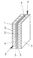
- a fuel cell is in a perspective view of reproduced above, the housing for reasons of improved Vividness has been omitted.
- the fuel cell includes one proton-conducting first layer 1, which on both sides of catalyst layers 5 is covered.
- gas permeable electrodes 2 On the outwardly facing surface of the catalyst layers 5 are gas permeable electrodes 2, which on the Side layers facing away from the catalyst layers 5, second layers 3 in shape touch electrically conductive plates.
- the first layer can consist of a proton-conducting polymer Made of material, but also made of a porous film, a fabric or Knitted fabric or a nonwoven fabric made of short or continuous fibers, which up to Saturation is filled with perfluorinated ionomer, the perfluorinated ionomer be a polytetrafluoroethylene with sulfonated perfluorovinyl ether side chains can.
- microfiber nonwoven with one to five molar, aqueous sulfuric acid solution or with concentrated Soak phosphoric acid.
- Non-woven fabric consists of microfibers, film fibrils or microfilaments.
- porous foils is also possible.
- materials PTFE and polysulfone have proven particularly effective.
- microfiber nonwoven fabric When using a microfiber nonwoven fabric as a proton conductor, it is provided that it is saturated with an electrolyte to saturation; wherein the microfiber nonwoven fabric is chemically inert to the electrolyte at temperatures up to +200 ° C and under oxidizing and reducing conditions, the weight of the microfiber nonwoven fabric being 20 to 200 g / m 2 ; where the nonwoven fabric thickness is a maximum of 1 mm and wherein the pore volume is: 65 to 92%.
- the average pore radius of the microfiber nonwoven should be 20 nm to 10 ⁇ m be.
- the second layers 3 are flat. You will be through Sheet metal plates formed.
- the electrodes 2 are arranged, which are each formed by a layer of carbonized fibers made of polyacrylonitrile, which are penetrated in several directions by channels 4 running parallel to their surfaces ,
- the layers consist of nonwovens made of carbonized polyacrylonitrile fibers with a titer of 35 dtex. They have a thickness of 4 mm and a weight per unit area of 180 g / m 2 . Both layers are constructed in multiple layers and each comprise an open-structured support layer between two higher-density cover layers, the fibers of which are arranged essentially perpendicular to the cover layers.
- the operating gases passed through during the intended use can thus pass through the channels while avoiding any significant pressure losses.
- the fibers extending transversely to the direction of flow nonetheless cause a certain swirling of the operating gases, as a result of which unused gas portions repeatedly come into contact with the first layer 1 or the catalyst layers 5 covering them. This is a great advantage for achieving a good energy yield.
- the layers contained in the two layers are inseparable, which makes assembly much easier.
- the insertion of all layers in the receiving, in the drawing Housing not shown must be made so that the during the intended use by the individual layers passed reaction gases 6, 7 only after reaction on the Catalyst surface through the layer 1 made of proton-conducting, polymeric Can not connect material through them however, directly.
- the first layer 1 and the third layers 3 can for this purpose the electrodes 2 in all directions in Reach over laterally the area of narrow edge strips, which are covered by sealing strips of the Housing detected and sealed in such a way. at Relatively little effort in terms of design can be achieved rule out that the operating gases 6, 7 bypassing the first layer 1 can come into direct contact with one another and react. This is of great advantage from a safety point of view.
- the fuel cell according to the invention is characterized by a simple structure and Cost-effective availability thanks to particularly good operational security and a favorable power-to-weight ratio. For applications in the field of automotive technology this is a great advantage.
Landscapes
- Chemical & Material Sciences (AREA)
- Chemical Kinetics & Catalysis (AREA)
- Electrochemistry (AREA)
- General Chemical & Material Sciences (AREA)
- Life Sciences & Earth Sciences (AREA)
- Engineering & Computer Science (AREA)
- Manufacturing & Machinery (AREA)
- Sustainable Development (AREA)
- Sustainable Energy (AREA)
- Fuel Cell (AREA)
- Inert Electrodes (AREA)
Description
Claims (7)
- Brennstoffzelle, umfassend ein Gehäuse, zumindest eine protonenleitende, erste Schicht (1), die beiderseits von Katalysatorschichten (5) überdeckt ist, gasdurchlässige Elektroden (2) auf den Katalysatorschichten (5) und beiderseits der ersten Schichten (1) angeordnete, zweite Schichten (3) in Gestalt elektrisch leitfähiger Platten, die die Elektroden (2) in dicht benachbarten Abständen elektrisch leitend berühren und gemeinsam mit den Elektroden (2) gasführende Kanäle (4) begrenzen, wobei die erste Schicht (1) oder die zweite Schicht (3) eine im wesentlichen eben ausgebildete Oberfläche aufweisen und wobei die Elektroden (2) durch zumindest eine Lage aus carbonisierten, elektrisch leitfähigen Fasern aus polymerem Werkstoff gebildet sind, die in zumindest einer Richtung von parallel zu ihren Oberflächen verlaufenden Strömungskanälen durchdrungen ist, dadurch gekennzeichnet, dass die Lage mehrschichtig aufgebaut und zwischen zwei höher verdichteten Deckschichten zumindest eine offen strukturierte Stützschicht umfasst.
- Brennstoffzelle nach Anspruch 1, dadurch gekennzeichnet, dass die Lage aus einem Vliesstoff, einem Gewebe oder einem Gewirk gebildet ist.
- Brennstoffzelle nach Anspruch 1 oder 2, dadurch gekennzeichnet, dass Fasern einen Titer von 10 bis 50 dtex haben.
- Brennstoffzelle nach einem der Ansprüche 1 bis 3, bei der die Lage aus polymeren Fasern besteht, dadurch gekennzeichnet, dass die Lage bei einer Dicke von 2 bis 6 mm ein Flächengewicht von 50 bis 250 g/m2 hat.
- Brennstoffzelle nach einem der Ansprüche 1 bis 4 dadurch gekennzeichnet, dass die die Stützschicht bildenden Fasern im wesentlichen senkrecht zu den Deckschichten verlaufend angeordnet sind.
- Brennstoffzelle nach Anspruch 5, dadurch gekennzeichnet, dass die Fasern im Zuge von Kanälen begrenzenden Gasen angeordnet sind.
- Brennstoffzelle nach einem der Ansprüche 1 bis 6, dadurch gekennzeichnet, dass in der Lage Fasern aus carbonisiertern Polyacrylnitril, Metall undloder Pech enthalten sind.
Applications Claiming Priority (3)
| Application Number | Priority Date | Filing Date | Title |
|---|---|---|---|
| DE19821976 | 1998-05-18 | ||
| DE19821976A DE19821976C2 (de) | 1998-05-18 | 1998-05-18 | Brennstoffzelle |
| PCT/EP1999/002201 WO1999060648A1 (de) | 1998-05-18 | 1999-03-31 | Brennstoffzelle |
Publications (2)
| Publication Number | Publication Date |
|---|---|
| EP1086504A1 EP1086504A1 (de) | 2001-03-28 |
| EP1086504B1 true EP1086504B1 (de) | 2003-06-18 |
Family
ID=7867975
Family Applications (1)
| Application Number | Title | Priority Date | Filing Date |
|---|---|---|---|
| EP99919165A Expired - Lifetime EP1086504B1 (de) | 1998-05-18 | 1999-03-31 | Brennstoffzelle |
Country Status (12)
| Country | Link |
|---|---|
| US (1) | US6630269B1 (de) |
| EP (1) | EP1086504B1 (de) |
| JP (1) | JP2002516470A (de) |
| KR (1) | KR20010072584A (de) |
| CN (1) | CN1300451A (de) |
| AT (1) | ATE243366T1 (de) |
| AU (1) | AU736973B2 (de) |
| BR (1) | BR9910534A (de) |
| CA (1) | CA2333237A1 (de) |
| DE (2) | DE19821976C2 (de) |
| WO (1) | WO1999060648A1 (de) |
| ZA (1) | ZA200006218B (de) |
Families Citing this family (6)
| Publication number | Priority date | Publication date | Assignee | Title |
|---|---|---|---|---|
| GB0020051D0 (en) * | 2000-08-16 | 2000-10-04 | Mat & Separations Tech Int Ltd | Improved fuel cell structure |
| DE10208275A1 (de) * | 2002-02-26 | 2003-09-04 | Creavis Tech & Innovation Gmbh | Flexible Elektrolytmembran auf Basis eines Polymerfasern umfassenden Trägers, Verfahren zu deren Herstellung und die Verwendung derselben |
| US7470483B2 (en) * | 2002-12-11 | 2008-12-30 | Panasonic Corporation | Electrolyte membrane-electrode assembly for fuel cell and operation method of fuel cell using the same |
| JP4568044B2 (ja) * | 2004-07-12 | 2010-10-27 | 株式会社日立製作所 | 膜電極複合体モジュール、燃料電池および電子機器並びに膜電極複合体モジュールの製造方法 |
| DE102016224696A1 (de) * | 2016-12-12 | 2018-06-14 | Robert Bosch Gmbh | Bipolarplatte für eine Brennstoffzelle und Brennstoffzelle |
| DE102017217901A1 (de) * | 2017-10-09 | 2019-04-11 | Robert Bosch Gmbh | Gasverteilerplatte für eine Brennstoffzelle |
Family Cites Families (7)
| Publication number | Priority date | Publication date | Assignee | Title |
|---|---|---|---|---|
| JPS59141170A (ja) * | 1983-01-31 | 1984-08-13 | Kureha Chem Ind Co Ltd | 燃料電池用電極基板及びその製造方法 |
| JPS62123662A (ja) * | 1985-11-25 | 1987-06-04 | Kureha Chem Ind Co Ltd | 燃料電池用電極基板 |
| US4759089A (en) * | 1987-04-28 | 1988-07-26 | Fox Theodore A | Cervical pillow |
| CN1048892A (zh) * | 1989-05-24 | 1991-01-30 | 奥本大学 | 混合纤维复合材料结构及其制法和用途 |
| US5252410A (en) * | 1991-09-13 | 1993-10-12 | Ballard Power Systems Inc. | Lightweight fuel cell membrane electrode assembly with integral reactant flow passages |
| US5292600A (en) | 1992-08-13 | 1994-03-08 | H-Power Corp. | Hydrogen power cell |
| DE19544323A1 (de) * | 1995-11-28 | 1997-06-05 | Magnet Motor Gmbh | Gasdiffusionselektrode für Polymerelektrolytmembran-Brennstoffzellen |
-
1998
- 1998-05-18 DE DE19821976A patent/DE19821976C2/de not_active Expired - Fee Related
-
1999
- 1999-03-31 KR KR1020007012936A patent/KR20010072584A/ko not_active Ceased
- 1999-03-31 US US09/700,001 patent/US6630269B1/en not_active Expired - Fee Related
- 1999-03-31 JP JP2000550168A patent/JP2002516470A/ja active Pending
- 1999-03-31 EP EP99919165A patent/EP1086504B1/de not_active Expired - Lifetime
- 1999-03-31 BR BR9910534-9A patent/BR9910534A/pt not_active IP Right Cessation
- 1999-03-31 WO PCT/EP1999/002201 patent/WO1999060648A1/de not_active Ceased
- 1999-03-31 DE DE59906013T patent/DE59906013D1/de not_active Expired - Fee Related
- 1999-03-31 CA CA002333237A patent/CA2333237A1/en not_active Abandoned
- 1999-03-31 AT AT99919165T patent/ATE243366T1/de not_active IP Right Cessation
- 1999-03-31 AU AU37037/99A patent/AU736973B2/en not_active Ceased
- 1999-03-31 CN CN99805931A patent/CN1300451A/zh active Pending
-
2000
- 2000-11-01 ZA ZA200006218A patent/ZA200006218B/xx unknown
Also Published As
| Publication number | Publication date |
|---|---|
| WO1999060648A1 (de) | 1999-11-25 |
| DE19821976C2 (de) | 2003-01-16 |
| US6630269B1 (en) | 2003-10-07 |
| ZA200006218B (en) | 2002-08-13 |
| BR9910534A (pt) | 2001-01-16 |
| DE19821976A1 (de) | 1999-11-25 |
| DE59906013D1 (de) | 2003-07-24 |
| EP1086504A1 (de) | 2001-03-28 |
| AU3703799A (en) | 1999-12-06 |
| CA2333237A1 (en) | 1999-11-25 |
| KR20010072584A (ko) | 2001-07-31 |
| JP2002516470A (ja) | 2002-06-04 |
| ATE243366T1 (de) | 2003-07-15 |
| CN1300451A (zh) | 2001-06-20 |
| AU736973B2 (en) | 2001-08-09 |
Similar Documents
| Publication | Publication Date | Title |
|---|---|---|
| EP0815609B1 (de) | Zusammenfassung von einzelzellen zu einer membranelektroden-einheit und deren verwendung | |
| EP0968542B1 (de) | Gasdiffusionselektrode mit verringertem diffusionsvermögen für wasser und polymerelektrolytmembran-brennstoffzelle | |
| WO2002025765A2 (de) | Elektrochemischer zellenstapel | |
| EP3884535B1 (de) | Brennstoffzellenplatte, bipolarplatte und brennstoffzellenvorrichtung | |
| DE19539959C2 (de) | Brennstoffzellenanordnung | |
| EP1760808A1 (de) | Elektroden für Brennstoffzellen | |
| DE2809815C3 (de) | Brennstoffzelle mit einer den Elektrolyten chemisch und physikalisch adsorbierenden Matrixschicht | |
| DE112010006075B4 (de) | Brennstoffzelle und Herstellungsverfahren dafür | |
| DE102013004799A1 (de) | Befeuchtungseinrichtung zur Befeuchtung von Prozessgasen sowie Brennstoffzellenanordnung umfassend eine solche | |
| EP1086504B1 (de) | Brennstoffzelle | |
| EP1653538A1 (de) | Kühlplattenmodul mit integralem Dichtungselement für einen Brennstoffzellenstack | |
| DE102013206789A1 (de) | Bipolarplatte für eine Brennstoffzelle, Verfahren zu ihrer Herstellung sowie Brennstoffzelle mit einer solchen Bipolarplatte | |
| DE10155349C2 (de) | Mikrobrennstoffzellensystem sowie Verfahren zu seiner Herstellung | |
| EP1088360B1 (de) | Brennstoffzelle | |
| EP3939109B1 (de) | Brennstoffzellenaufbau, brennstoffzellensystem und brennstoffzellenfahrzeug | |
| WO2012080245A1 (de) | Membran-elektroden-anordnung mit zwei deckschichten | |
| DE102009011239A1 (de) | Niedertemperatur-Brennstoffzelle mit integriertem Wassermanagementsystem für den passiven Austrag von Produktwasser | |
| WO2017025557A1 (de) | Membran-elektroden-einheit für eine brennstoffzelle sowie brennstoffzelle | |
| DE19916239C2 (de) | Brennstoffzelle | |
| DE102018212498A1 (de) | Elektrode für eine Brennstoffzelle oder einen Stapel von Brennstoffzellen | |
| DE202024101888U1 (de) | Metallische Bipolarplatte für ein elektrochemisches System | |
| DE102015222245A1 (de) | Polarplatte für einen Brennstoffzellenstapel | |
| DE102023118254A1 (de) | Redox-Flow-Converter | |
| DE102021209735A1 (de) | Verteilerplatte für eine elektrochemische Zelle und elektrochemische Zelle | |
| DE102004028142A1 (de) | Bipolarseparator |
Legal Events
| Date | Code | Title | Description |
|---|---|---|---|
| PUAI | Public reference made under article 153(3) epc to a published international application that has entered the european phase |
Free format text: ORIGINAL CODE: 0009012 |
|
| 17P | Request for examination filed |
Effective date: 20000902 |
|
| AK | Designated contracting states |
Kind code of ref document: A1 Designated state(s): AT DE ES FR GB IT SE |
|
| RAP1 | Party data changed (applicant data changed or rights of an application transferred) |
Owner name: CARL FREUDENBERG KG |
|
| GRAH | Despatch of communication of intention to grant a patent |
Free format text: ORIGINAL CODE: EPIDOS IGRA |
|
| GRAH | Despatch of communication of intention to grant a patent |
Free format text: ORIGINAL CODE: EPIDOS IGRA |
|
| GRAA | (expected) grant |
Free format text: ORIGINAL CODE: 0009210 |
|
| AK | Designated contracting states |
Designated state(s): AT DE ES FR GB IT SE |
|
| PG25 | Lapsed in a contracting state [announced via postgrant information from national office to epo] |
Ref country code: IT Free format text: LAPSE BECAUSE OF FAILURE TO SUBMIT A TRANSLATION OF THE DESCRIPTION OR TO PAY THE FEE WITHIN THE PRESCRIBED TIME-LIMIT;WARNING: LAPSES OF ITALIAN PATENTS WITH EFFECTIVE DATE BEFORE 2007 MAY HAVE OCCURRED AT ANY TIME BEFORE 2007. THE CORRECT EFFECTIVE DATE MAY BE DIFFERENT FROM THE ONE RECORDED. Effective date: 20030618 Ref country code: FR Free format text: LAPSE BECAUSE OF FAILURE TO SUBMIT A TRANSLATION OF THE DESCRIPTION OR TO PAY THE FEE WITHIN THE PRESCRIBED TIME-LIMIT Effective date: 20030618 |
|
| REG | Reference to a national code |
Ref country code: GB Ref legal event code: FG4D Free format text: NOT ENGLISH |
|
| REF | Corresponds to: |
Ref document number: 59906013 Country of ref document: DE Date of ref document: 20030724 Kind code of ref document: P |
|
| GBT | Gb: translation of ep patent filed (gb section 77(6)(a)/1977) | ||
| PG25 | Lapsed in a contracting state [announced via postgrant information from national office to epo] |
Ref country code: SE Free format text: LAPSE BECAUSE OF FAILURE TO SUBMIT A TRANSLATION OF THE DESCRIPTION OR TO PAY THE FEE WITHIN THE PRESCRIBED TIME-LIMIT Effective date: 20030918 |
|
| PG25 | Lapsed in a contracting state [announced via postgrant information from national office to epo] |
Ref country code: ES Free format text: LAPSE BECAUSE OF FAILURE TO SUBMIT A TRANSLATION OF THE DESCRIPTION OR TO PAY THE FEE WITHIN THE PRESCRIBED TIME-LIMIT Effective date: 20030929 |
|
| PG25 | Lapsed in a contracting state [announced via postgrant information from national office to epo] |
Ref country code: GB Free format text: LAPSE BECAUSE OF NON-PAYMENT OF DUE FEES Effective date: 20040331 Ref country code: AT Free format text: LAPSE BECAUSE OF NON-PAYMENT OF DUE FEES Effective date: 20040331 |
|
| PLBE | No opposition filed within time limit |
Free format text: ORIGINAL CODE: 0009261 |
|
| STAA | Information on the status of an ep patent application or granted ep patent |
Free format text: STATUS: NO OPPOSITION FILED WITHIN TIME LIMIT |
|
| 26N | No opposition filed |
Effective date: 20040319 |
|
| EN | Fr: translation not filed | ||
| PG25 | Lapsed in a contracting state [announced via postgrant information from national office to epo] |
Ref country code: DE Free format text: LAPSE BECAUSE OF NON-PAYMENT OF DUE FEES Effective date: 20041001 |
|
| GBPC | Gb: european patent ceased through non-payment of renewal fee |