EP1086318B1 - Couplage souple destine a l'arbre de l'unite d'entrainement d'une pompe a perfusion - Google Patents
Couplage souple destine a l'arbre de l'unite d'entrainement d'une pompe a perfusion Download PDFInfo
- Publication number
- EP1086318B1 EP1086318B1 EP99928739A EP99928739A EP1086318B1 EP 1086318 B1 EP1086318 B1 EP 1086318B1 EP 99928739 A EP99928739 A EP 99928739A EP 99928739 A EP99928739 A EP 99928739A EP 1086318 B1 EP1086318 B1 EP 1086318B1
- Authority
- EP
- European Patent Office
- Prior art keywords
- sleeve
- coupling
- driven shaft
- elastomeric member
- shaft
- Prior art date
- Legal status (The legal status is an assumption and is not a legal conclusion. Google has not performed a legal analysis and makes no representation as to the accuracy of the status listed.)
- Expired - Lifetime
Links
Images
Classifications
-
- F—MECHANICAL ENGINEERING; LIGHTING; HEATING; WEAPONS; BLASTING
- F04—POSITIVE - DISPLACEMENT MACHINES FOR LIQUIDS; PUMPS FOR LIQUIDS OR ELASTIC FLUIDS
- F04B—POSITIVE-DISPLACEMENT MACHINES FOR LIQUIDS; PUMPS
- F04B17/00—Pumps characterised by combination with, or adaptation to, specific driving engines or motors
- F04B17/03—Pumps characterised by combination with, or adaptation to, specific driving engines or motors driven by electric motors
-
- A—HUMAN NECESSITIES
- A61—MEDICAL OR VETERINARY SCIENCE; HYGIENE
- A61M—DEVICES FOR INTRODUCING MEDIA INTO, OR ONTO, THE BODY; DEVICES FOR TRANSDUCING BODY MEDIA OR FOR TAKING MEDIA FROM THE BODY; DEVICES FOR PRODUCING OR ENDING SLEEP OR STUPOR
- A61M5/00—Devices for bringing media into the body in a subcutaneous, intra-vascular or intramuscular way; Accessories therefor, e.g. filling or cleaning devices, arm-rests
- A61M5/14—Infusion devices, e.g. infusing by gravity; Blood infusion; Accessories therefor
- A61M5/142—Pressure infusion, e.g. using pumps
- A61M5/14212—Pumping with an aspiration and an expulsion action
- A61M5/14224—Diaphragm type
-
- F—MECHANICAL ENGINEERING; LIGHTING; HEATING; WEAPONS; BLASTING
- F16—ENGINEERING ELEMENTS AND UNITS; GENERAL MEASURES FOR PRODUCING AND MAINTAINING EFFECTIVE FUNCTIONING OF MACHINES OR INSTALLATIONS; THERMAL INSULATION IN GENERAL
- F16D—COUPLINGS FOR TRANSMITTING ROTATION; CLUTCHES; BRAKES
- F16D3/00—Yielding couplings, i.e. with means permitting movement between the connected parts during the drive
- F16D3/50—Yielding couplings, i.e. with means permitting movement between the connected parts during the drive with the coupling parts connected by one or more intermediate members
- F16D3/72—Yielding couplings, i.e. with means permitting movement between the connected parts during the drive with the coupling parts connected by one or more intermediate members with axially-spaced attachments to the coupling parts
- F16D3/74—Yielding couplings, i.e. with means permitting movement between the connected parts during the drive with the coupling parts connected by one or more intermediate members with axially-spaced attachments to the coupling parts the intermediate member or members being made of rubber or other rubber-like flexible material
-
- Y—GENERAL TAGGING OF NEW TECHNOLOGICAL DEVELOPMENTS; GENERAL TAGGING OF CROSS-SECTIONAL TECHNOLOGIES SPANNING OVER SEVERAL SECTIONS OF THE IPC; TECHNICAL SUBJECTS COVERED BY FORMER USPC CROSS-REFERENCE ART COLLECTIONS [XRACs] AND DIGESTS
- Y10—TECHNICAL SUBJECTS COVERED BY FORMER USPC
- Y10T—TECHNICAL SUBJECTS COVERED BY FORMER US CLASSIFICATION
- Y10T403/00—Joints and connections
- Y10T403/45—Flexibly connected rigid members
- Y10T403/453—Flexible sleeve-type coupling
-
- Y—GENERAL TAGGING OF NEW TECHNOLOGICAL DEVELOPMENTS; GENERAL TAGGING OF CROSS-SECTIONAL TECHNOLOGIES SPANNING OVER SEVERAL SECTIONS OF THE IPC; TECHNICAL SUBJECTS COVERED BY FORMER USPC CROSS-REFERENCE ART COLLECTIONS [XRACs] AND DIGESTS
- Y10—TECHNICAL SUBJECTS COVERED BY FORMER USPC
- Y10T—TECHNICAL SUBJECTS COVERED BY FORMER US CLASSIFICATION
- Y10T403/00—Joints and connections
- Y10T403/45—Flexibly connected rigid members
- Y10T403/455—Elastomer interposed between radially spaced members
- Y10T403/458—Composite bushing with elastomeric component
-
- Y—GENERAL TAGGING OF NEW TECHNOLOGICAL DEVELOPMENTS; GENERAL TAGGING OF CROSS-SECTIONAL TECHNOLOGIES SPANNING OVER SEVERAL SECTIONS OF THE IPC; TECHNICAL SUBJECTS COVERED BY FORMER USPC CROSS-REFERENCE ART COLLECTIONS [XRACs] AND DIGESTS
- Y10—TECHNICAL SUBJECTS COVERED BY FORMER USPC
- Y10T—TECHNICAL SUBJECTS COVERED BY FORMER US CLASSIFICATION
- Y10T403/00—Joints and connections
- Y10T403/57—Distinct end coupler
- Y10T403/5733—Plural opposed sockets
Definitions
- US 2,297,619 discloses a rubber coupling for compensating any misalignment between two motor shafts.
- the coupling comprises a central body portion made of resilient rubber while hard rubber ends are vulcanized thereto and to washers (made of metal and provided with a D-shaped central aperture) which are embedded therein.
- US 3,057,647 discloses a plastic shaft coupler for use in an electric clock timer mechanism comprising a shaft receiving sleeve adaptable to accommodate two axially aligned shafts and an outer collar. Moreover, series of longitudinal slots extending from one end separate the sleeve into a plurality of circumferentially spaced axially extending resilient fingers.
- the fitting further comprises a web that is disposed transverse to a longitudinal axis of the fitting, between the first opening and the second opening.
- This web limits a depth to which the drive shaft and the driven shaft are advanced into the first opening and the second opening, respectively. Also, the web limits vibration of the drive shaft propagating into the driven shaft from the drive shaft.
- a sleeve that is sized to snugly fit around an outer surface of the fitting in an interference fit provides a compression force that helps to keep the fitting seated on the drive shaft.
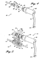
- An outer surface of the sleeve includes a cam surface adapted to act on a plunger. As the drive shaft rotates the driven shaft, the sleeve causes the plunger to move along a longitudinal axis of the plunger.
- the cam surface is adapted to only apply a force against the plunger in one direction; the plunger is biased in an opposite direction by an elastomeric membrane which the plunger displaces.
- the elastomeric fitting thus minimizes vibration transmission between the drive shaft and the driven shaft and helps to minimize audible noise. Because of its elasticity, the fitting can accommodate at least a limited degree of misalignment between the drive shaft and the driven shaft.
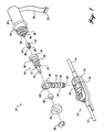
- Pump cassette 10 is disposable, being intended for use with a single patient. Details of the pump cassette are disclosed in commonly assigned U.S. Patent No. 5,586,868. Proximal tubing 14 and distal tubing 16 are coupled to the proximal and distal ends of the pump cassette. A reservoir (not shown) of medicinal fluid is connected to proximal tubing 14, while distal tubing 16 is connected into a patient's cardiovascular system to infuse the medicinal fluid at a rate determined by the speed with which pump cassette 10 is driven.
- Pump cassette 10 includes a plastic housing 12 having an opening 18 formed in an upper surface thereof.
- an opening 80 having a flat 82 on one side and therefore also being generally "D"-shaped in cross section.
- a flat 84 is formed on the end of driven shaft 40, so that it is also “D"-shaped, but slightly larger in size than opening 80.
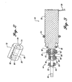
- a transverse web 98 (shown in FIGURE 2) is disposed within coupling 42, separating opening 74 from opening 80 and limiting the extent to which drive shaft 38 and driven shaft 40 extend within coupling 42. Transverse web 98 also limits the transmission of vibration from drive shaft 38 to driven shaft 40, since it prevents the ends of the drive shaft and driven shaft from contacting each other.
- Sleeve 86 has an opening 88 with an internal diameter approximately equal to the external diameter of coupling 42. Further, a longitudinally extending notch 90 having a cross-sectional profile and size corresponding to that of rib 72 is formed on one side of opening 88 to receive the rib when sleeve 86 is slipped over coupling 42. It will be apparent that coupling 42 could alternatively be provided with a notch to receive a correspondingly shaped and sized rib formed on the inner surface of the opening into sleeve 86, to key the coupling and sleeve.
- sleeve 86 is an overmolded component that includes a rigid internal element (not shown) formed of a hard plastic or metal material, which is coated or overmolded with an elastomeric material - preferably synthetic rubber.
- coupling 42 eliminates the need for mechanical fasteners to attach drive shaft 38 to driven shaft 40 and decreases the noise level of the drive assembly, since vibration in the motor is at least partially isolated from components of the drive assembly that are downstream of coupling 42.
- coupling 42 is relatively smaller and compact.
- assembly of the coupling and sleeve is relatively simple, so that a decrease in assembly time and the number of parts, and a corresponding resultant cost reduction in the drive assembly is achieved by using coupling 42 and sleeve 86 rather than a prior art type coupling.
Claims (6)
- Ensemble de couplage élastique destiné à transmettre une force d'entraínement rotative depuis un premier arbre (38) vers un second arbre (40), ledit ensemble comprenant :(a) un élément élastomère (42) globalement allongé ayant :(i) un premier orifice (74) disposé à une extrémité de l'élément élastomère et dimensionné pour créer un ajustement avec serrage sur le premier arbre (38) ; et(ii) un second orifice (80) disposé à une extrémité opposée de l'élément élastomère et dimensionné pour créer un ajustement avec serrage sur le second arbre (40) ; et(b) un manchon allongé (86) ayant une ouverture centrale qui est dimensionnée pour créer un ajustement avec serrage sur une surface extérieure de l'élément élastomère et fournissant une force de compression contre l'élément élastomère qui retient ce dernier sur au moins l'un des premier (38) et second (40) arbres, de sorte que les arbres (38, 40) soient couplés par l'intermédiaire de l'élément élastomère, dans lequel une surface extérieure du manchon (86) comprend une surface de came (96) ayant un profil qui définit un lieu de points à un rayon différent autour d'un axe central de l'élément élastomère ; et(c) une pièce intermédiaire ayant une ouverture globalement quadrilatérale à travers laquelle le manchon (86) s'étend, ladite pièce intermédiaire se déplaçant contre la surface de came (96) du manchon (86) lorsque le manchon (86) tourne.
- Ensemble de couplage élastique selon la revendication 1, dans lequel l'élément élastomère (42) comprend une bande (98) qui s'étend de manière transversale et est disposée entre le premier orifice (74) et le second orifice (80).
- Ensemble de couplage élastique selon la revendication 1, dans lequel au moins un élément parmi le manchon (86) et la surface extérieure de l'élément élastomère (42) comprend une rainure d'alignement pour claveter la position de l'arbre entraíné (40).
- Ensemble de couplage élastique selon la revendication 3, dans lequel un autre élément parmi le manchon (86) et la surface extérieure de l'élément élastomère (42) comprend une arête d'alignement, dimensionnée pour s'insérer dans la rainure d'alignement, ladite rainure d'alignement et ladite arête d'alignement coopérant ensemble pour créer l'ajustement avec serrage entre l'élément élastomère et le manchon (86).
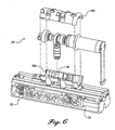
- Ensemble de couplage élastique selon la revendication 1, dans lequel la pièce intermédiaire est couplée à un piston plongeur (58) qui est entraíné pour se déplacer dans une direction éloignée du manchon (86) lorsque la surface de came (96) se déplace contre un côté de l'ouverture quadrilatérale.
- Ensemble de couplage élastique selon la revendication 1, dans lequel le manchon (86) comprend un matériau élastomère qui est surmoulé sur un matériau rigide.
Applications Claiming Priority (3)
| Application Number | Priority Date | Filing Date | Title |
|---|---|---|---|
| US09/100,621 US6471436B1 (en) | 1998-06-19 | 1998-06-19 | Elastomeric connector coupling motor to cam actuator of infusion pump |
| US100621 | 1998-06-19 | ||
| PCT/US1999/013664 WO1999066225A1 (fr) | 1998-06-19 | 1999-06-18 | Couplage souple destine a l'arbre de l'unite d'entrainement d'une pompe a perfusion |
Publications (2)
| Publication Number | Publication Date |
|---|---|
| EP1086318A1 EP1086318A1 (fr) | 2001-03-28 |
| EP1086318B1 true EP1086318B1 (fr) | 2005-11-16 |
Family
ID=22280682
Family Applications (1)
| Application Number | Title | Priority Date | Filing Date |
|---|---|---|---|
| EP99928739A Expired - Lifetime EP1086318B1 (fr) | 1998-06-19 | 1999-06-18 | Couplage souple destine a l'arbre de l'unite d'entrainement d'une pompe a perfusion |
Country Status (9)
| Country | Link |
|---|---|
| US (1) | US6471436B1 (fr) |
| EP (1) | EP1086318B1 (fr) |
| JP (1) | JP4448250B2 (fr) |
| AT (1) | ATE310181T1 (fr) |
| AU (1) | AU756871B2 (fr) |
| CA (1) | CA2335156C (fr) |
| DE (1) | DE69928400T2 (fr) |
| ES (1) | ES2252950T3 (fr) |
| WO (1) | WO1999066225A1 (fr) |
Families Citing this family (14)
| Publication number | Priority date | Publication date | Assignee | Title |
|---|---|---|---|---|
| ES2737835T3 (es) | 2003-04-23 | 2020-01-16 | Valeritas Inc | Bomba accionada hidráulicamente para la administración de medicamentos de larga duración |
| US9089636B2 (en) | 2004-07-02 | 2015-07-28 | Valeritas, Inc. | Methods and devices for delivering GLP-1 and uses thereof |
| GB2425062B (en) | 2005-04-06 | 2010-07-21 | Cilag Ag Int | Injection device |
| SG173319A1 (en) | 2006-03-30 | 2011-08-29 | Valeritas Inc | Multi-cartridge fluid delivery device |
| DE202007004690U1 (de) * | 2007-03-30 | 2008-08-14 | Robert Bosch Gmbh | Lagereinheit und damit ausgestattete Lineareinheit |
| EP2047872B1 (fr) * | 2007-10-08 | 2010-09-08 | Ais Gmbh Aachen Innovative Solutions | Dispositif de cathéter |
| US8105269B2 (en) | 2008-10-24 | 2012-01-31 | Baxter International Inc. | In situ tubing measurements for infusion pumps |
| US8137083B2 (en) | 2009-03-11 | 2012-03-20 | Baxter International Inc. | Infusion pump actuators, system and method for controlling medical fluid flowrate |
| US8382447B2 (en) | 2009-12-31 | 2013-02-26 | Baxter International, Inc. | Shuttle pump with controlled geometry |
| US8567235B2 (en) | 2010-06-29 | 2013-10-29 | Baxter International Inc. | Tube measurement technique using linear actuator and pressure sensor |
| US9714650B2 (en) | 2013-06-11 | 2017-07-25 | Matthew G. Morris, Jr. | Pumping system |
| CN110869072B (zh) | 2017-05-30 | 2021-12-10 | 西部制药服务有限公司(以色列) | 用于穿戴式注射器的模块化驱动机构 |
| JP6810816B2 (ja) | 2017-05-30 | 2021-01-06 | ウェスト ファーマ サービシーズ イスラエル リミテッド | 注射器の雑音および振動減衰マウントモジュール |
| CN110259838A (zh) * | 2019-07-09 | 2019-09-20 | 太仓市海谷五金机电设备有限公司 | 一种油泵动力输入结构 |
Family Cites Families (9)
| Publication number | Priority date | Publication date | Assignee | Title |
|---|---|---|---|---|
| US2297619A (en) | 1940-01-27 | 1942-09-29 | Murray Corp | Motor coupling |
| US2857749A (en) * | 1956-08-14 | 1958-10-28 | Nylo Flex Products Company | Flexible coupling |
| US2898751A (en) * | 1957-12-16 | 1959-08-11 | Chemstrand Corp | Flexible coupling |
| US3057647A (en) | 1961-01-24 | 1962-10-09 | Gen Time Corp | Shaft coupler |
| US3423957A (en) * | 1966-09-30 | 1969-01-28 | Monogram Ind Inc | Coupling |
| US4391600A (en) | 1979-03-09 | 1983-07-05 | Avi, Inc. | Nonpulsating IV pump and disposable pump chamber |
| US5347881A (en) * | 1991-09-19 | 1994-09-20 | Dana Corporation | Damper assembly for shift lever mechanism |
| US5586867A (en) | 1994-01-19 | 1996-12-24 | Mehlos; Michael D. | Direct mounted fan apparatus |
| CA2190098C (fr) | 1994-05-13 | 2006-04-25 | Michael W. Lawless | Cassette a chambre de pompage de perfusion de liquide jettable dotee d'un interrupteur d'ecoulement a bouton poussoir |
-
1998
- 1998-06-19 US US09/100,621 patent/US6471436B1/en not_active Expired - Fee Related
-
1999
- 1999-06-18 AU AU45733/99A patent/AU756871B2/en not_active Ceased
- 1999-06-18 JP JP2000555011A patent/JP4448250B2/ja not_active Expired - Fee Related
- 1999-06-18 EP EP99928739A patent/EP1086318B1/fr not_active Expired - Lifetime
- 1999-06-18 AT AT99928739T patent/ATE310181T1/de not_active IP Right Cessation
- 1999-06-18 CA CA002335156A patent/CA2335156C/fr not_active Expired - Fee Related
- 1999-06-18 ES ES99928739T patent/ES2252950T3/es not_active Expired - Lifetime
- 1999-06-18 DE DE69928400T patent/DE69928400T2/de not_active Expired - Lifetime
- 1999-06-18 WO PCT/US1999/013664 patent/WO1999066225A1/fr active IP Right Grant
Also Published As
| Publication number | Publication date |
|---|---|
| CA2335156C (fr) | 2009-01-06 |
| DE69928400D1 (de) | 2005-12-22 |
| EP1086318A1 (fr) | 2001-03-28 |
| AU756871B2 (en) | 2003-01-23 |
| AU4573399A (en) | 2000-01-05 |
| WO1999066225A1 (fr) | 1999-12-23 |
| ATE310181T1 (de) | 2005-12-15 |
| CA2335156A1 (fr) | 1999-12-23 |
| US6471436B1 (en) | 2002-10-29 |
| JP2002518644A (ja) | 2002-06-25 |
| ES2252950T3 (es) | 2006-05-16 |
| DE69928400T2 (de) | 2006-08-10 |
| JP4448250B2 (ja) | 2010-04-07 |
Similar Documents
| Publication | Publication Date | Title |
|---|---|---|
| EP1086318B1 (fr) | Couplage souple destine a l'arbre de l'unite d'entrainement d'une pompe a perfusion | |
| US4515535A (en) | Peristaltic pump quick disconnect rotor assembly | |
| JP3953030B2 (ja) | ファンアイドラプーリ | |
| US4755109A (en) | Snap-together peristaltic mechanism | |
| US8217543B2 (en) | Electromagnetic clutch | |
| US6375577B1 (en) | Universal style coupling | |
| MXPA05002362A (es) | Montaje que incluye un motor electrico y un receptor. | |
| US5562360A (en) | Spindle connector for powder/liquid feeding systems | |
| CA2581733C (fr) | Connecteur elastomerique raccordant un moteur a l'actionneur a came d'une pompe a perfusion | |
| TW202043618A (zh) | 管泵、旋轉限制部件、軸體和軸連接結構 | |
| JP4128221B2 (ja) | 車両ブレーキシステムに用いられるポンプユニット | |
| JPS62501985A (ja) | 機械的シ−ル | |
| US6162125A (en) | Motor shaft to gear pump coupling device for fluid borne noise reduction | |
| US3084852A (en) | Fan blade hub connector | |
| JPH0587690B2 (fr) | ||
| KR100307678B1 (ko) | 센서 하우징과 센서 바디의 결합장치 | |
| US3367141A (en) | Rotary shaft coupling | |
| US5854695A (en) | Document transmitting interval retainer for a facsimile | |
| GB2347480A (en) | Motor driving system | |
| CN213637348U (zh) | 一种用于纺纱的驱动电机 | |
| KR102647957B1 (ko) | 회전 커넥터 | |
| JPH04191535A (ja) | ワンウエイクラッチ及びこのワンウエイクラッチを組込んだ伝動装置 | |
| KR102488831B1 (ko) | 안전커버장치가 구비된 동력전달 조인트 | |
| CN220603851U (zh) | 一种鼓单元及处理盒 | |
| MXPA94003079A (es) | Dispositivo y metodo para la retencion de una cubierta de flecha flexible. |
Legal Events
| Date | Code | Title | Description |
|---|---|---|---|
| PUAI | Public reference made under article 153(3) epc to a published international application that has entered the european phase |
Free format text: ORIGINAL CODE: 0009012 |
|
| 17P | Request for examination filed |
Effective date: 20001207 |
|
| AK | Designated contracting states |
Kind code of ref document: A1 Designated state(s): AT BE CH CY DE DK ES FI FR GB GR IE IT LI LU NL PT SE |
|
| 17Q | First examination report despatched |
Effective date: 20040517 |
|
| RAP1 | Party data changed (applicant data changed or rights of an application transferred) |
Owner name: HOSPIRA, INC. |
|
| GRAP | Despatch of communication of intention to grant a patent |
Free format text: ORIGINAL CODE: EPIDOSNIGR1 |
|
| GRAS | Grant fee paid |
Free format text: ORIGINAL CODE: EPIDOSNIGR3 |
|
| GRAA | (expected) grant |
Free format text: ORIGINAL CODE: 0009210 |
|
| AK | Designated contracting states |
Kind code of ref document: B1 Designated state(s): AT BE CH CY DE DK ES FI FR GB GR IE IT LI LU NL PT SE |
|
| PG25 | Lapsed in a contracting state [announced via postgrant information from national office to epo] |
Ref country code: NL Free format text: LAPSE BECAUSE OF FAILURE TO SUBMIT A TRANSLATION OF THE DESCRIPTION OR TO PAY THE FEE WITHIN THE PRESCRIBED TIME-LIMIT Effective date: 20051116 Ref country code: LI Free format text: LAPSE BECAUSE OF FAILURE TO SUBMIT A TRANSLATION OF THE DESCRIPTION OR TO PAY THE FEE WITHIN THE PRESCRIBED TIME-LIMIT Effective date: 20051116 Ref country code: FI Free format text: LAPSE BECAUSE OF FAILURE TO SUBMIT A TRANSLATION OF THE DESCRIPTION OR TO PAY THE FEE WITHIN THE PRESCRIBED TIME-LIMIT Effective date: 20051116 Ref country code: CH Free format text: LAPSE BECAUSE OF FAILURE TO SUBMIT A TRANSLATION OF THE DESCRIPTION OR TO PAY THE FEE WITHIN THE PRESCRIBED TIME-LIMIT Effective date: 20051116 Ref country code: BE Free format text: LAPSE BECAUSE OF FAILURE TO SUBMIT A TRANSLATION OF THE DESCRIPTION OR TO PAY THE FEE WITHIN THE PRESCRIBED TIME-LIMIT Effective date: 20051116 Ref country code: AT Free format text: LAPSE BECAUSE OF FAILURE TO SUBMIT A TRANSLATION OF THE DESCRIPTION OR TO PAY THE FEE WITHIN THE PRESCRIBED TIME-LIMIT Effective date: 20051116 |
|
| REG | Reference to a national code |
Ref country code: GB Ref legal event code: FG4D |
|
| REG | Reference to a national code |
Ref country code: CH Ref legal event code: EP |
|
| REG | Reference to a national code |
Ref country code: IE Ref legal event code: FG4D |
|
| REF | Corresponds to: |
Ref document number: 69928400 Country of ref document: DE Date of ref document: 20051222 Kind code of ref document: P |
|
| PG25 | Lapsed in a contracting state [announced via postgrant information from national office to epo] |
Ref country code: SE Free format text: LAPSE BECAUSE OF FAILURE TO SUBMIT A TRANSLATION OF THE DESCRIPTION OR TO PAY THE FEE WITHIN THE PRESCRIBED TIME-LIMIT Effective date: 20060216 Ref country code: GR Free format text: LAPSE BECAUSE OF FAILURE TO SUBMIT A TRANSLATION OF THE DESCRIPTION OR TO PAY THE FEE WITHIN THE PRESCRIBED TIME-LIMIT Effective date: 20060216 Ref country code: DK Free format text: LAPSE BECAUSE OF FAILURE TO SUBMIT A TRANSLATION OF THE DESCRIPTION OR TO PAY THE FEE WITHIN THE PRESCRIBED TIME-LIMIT Effective date: 20060216 |
|
| PG25 | Lapsed in a contracting state [announced via postgrant information from national office to epo] |
Ref country code: PT Free format text: LAPSE BECAUSE OF FAILURE TO SUBMIT A TRANSLATION OF THE DESCRIPTION OR TO PAY THE FEE WITHIN THE PRESCRIBED TIME-LIMIT Effective date: 20060417 |
|
| PGFP | Annual fee paid to national office [announced via postgrant information from national office to epo] |
Ref country code: IE Payment date: 20060420 Year of fee payment: 8 |
|
| NLV1 | Nl: lapsed or annulled due to failure to fulfill the requirements of art. 29p and 29m of the patents act | ||
| REG | Reference to a national code |
Ref country code: ES Ref legal event code: FG2A Ref document number: 2252950 Country of ref document: ES Kind code of ref document: T3 |
|
| REG | Reference to a national code |
Ref country code: CH Ref legal event code: PL |
|
| ET | Fr: translation filed | ||
| PLBE | No opposition filed within time limit |
Free format text: ORIGINAL CODE: 0009261 |
|
| STAA | Information on the status of an ep patent application or granted ep patent |
Free format text: STATUS: NO OPPOSITION FILED WITHIN TIME LIMIT |
|
| 26N | No opposition filed |
Effective date: 20060817 |
|
| REG | Reference to a national code |
Ref country code: IE Ref legal event code: MM4A |
|
| PG25 | Lapsed in a contracting state [announced via postgrant information from national office to epo] |
Ref country code: IE Free format text: LAPSE BECAUSE OF NON-PAYMENT OF DUE FEES Effective date: 20070618 |
|
| PG25 | Lapsed in a contracting state [announced via postgrant information from national office to epo] |
Ref country code: LU Free format text: LAPSE BECAUSE OF NON-PAYMENT OF DUE FEES Effective date: 20060618 |
|
| PG25 | Lapsed in a contracting state [announced via postgrant information from national office to epo] |
Ref country code: CY Free format text: LAPSE BECAUSE OF FAILURE TO SUBMIT A TRANSLATION OF THE DESCRIPTION OR TO PAY THE FEE WITHIN THE PRESCRIBED TIME-LIMIT Effective date: 20051116 |
|
| PGFP | Annual fee paid to national office [announced via postgrant information from national office to epo] |
Ref country code: GB Payment date: 20120525 Year of fee payment: 14 Ref country code: FR Payment date: 20120614 Year of fee payment: 14 |
|
| PGFP | Annual fee paid to national office [announced via postgrant information from national office to epo] |
Ref country code: IT Payment date: 20120619 Year of fee payment: 14 |
|
| PGFP | Annual fee paid to national office [announced via postgrant information from national office to epo] |
Ref country code: DE Payment date: 20120629 Year of fee payment: 14 Ref country code: ES Payment date: 20120618 Year of fee payment: 14 |
|
| GBPC | Gb: european patent ceased through non-payment of renewal fee |
Effective date: 20130618 |
|
| REG | Reference to a national code |
Ref country code: FR Ref legal event code: ST Effective date: 20140228 |
|
| REG | Reference to a national code |
Ref country code: DE Ref legal event code: R119 Ref document number: 69928400 Country of ref document: DE Effective date: 20140101 |
|
| PG25 | Lapsed in a contracting state [announced via postgrant information from national office to epo] |
Ref country code: GB Free format text: LAPSE BECAUSE OF NON-PAYMENT OF DUE FEES Effective date: 20130618 Ref country code: DE Free format text: LAPSE BECAUSE OF NON-PAYMENT OF DUE FEES Effective date: 20140101 |
|
| PG25 | Lapsed in a contracting state [announced via postgrant information from national office to epo] |
Ref country code: FR Free format text: LAPSE BECAUSE OF NON-PAYMENT OF DUE FEES Effective date: 20130701 Ref country code: IT Free format text: LAPSE BECAUSE OF NON-PAYMENT OF DUE FEES Effective date: 20130618 |
|
| REG | Reference to a national code |
Ref country code: ES Ref legal event code: FD2A Effective date: 20140707 |
|
| PG25 | Lapsed in a contracting state [announced via postgrant information from national office to epo] |
Ref country code: ES Free format text: LAPSE BECAUSE OF NON-PAYMENT OF DUE FEES Effective date: 20130619 |