Technical Field
The present invention relates to a plate heat
exchanger, and more particularly to a plate heat exchanger
for exchanging heat between two fluids flowing alternately
through adjacent fluid passages between piled plates, which
is suitable for such cases where at least one of the fluids
is a low-pressure vapor, or is evaporated with phase change,
or is condensed from a vapor, as an evaporator, a low-temperature
generator, or a condenser in a refrigerating
machine using a low-pressure refrigerant.
Background Art
A conventional plate heat exchanger is shown in FIGS.
10 and 11. FIGS. 10A and 10B are schematic views showing a
conventional plate heat exchanger, FIG. 10A is a front view,
and FIG. 10B is a side view. FIG. 11 is an exploded
explanatory view of FIGS. 10A and 10B.
In the conventional plate heat exchanger, as shown
in FIGS. 10A, 10B and 11, two plates 3 having opening
portions 5 at both ends thereof are piled on each other to
form a space therebetween, and the peripheral portions of
the plates 3 are sealed to form a heat exchange element 2.
The heat exchange elements 2 are piled on and combined with
each other in such a state that the opening portions 5 of
the plates 3 communicate with each other, thereby producing
a heat exchange structure. This heat exchange structure is
housed in a shell 20, and fluids flow through the interior
and the exterior of the heat exchange elements 2 so as to
exchange heat with each other.
Such a conventional plate heat exchanger requires
not only heat exchange elements composed of plates, but also
a shell. Thus, such a conventional plate heat exchanger has
been problematic in that manufacturing procedure is
complicated and various types of components are required.
FIG. 12 shows an example of an absorber and an
evaporator utilizing conventional plate heat exchangers.
In the conventional example shown in FIG. 12, an
evaporator 21 and an absorber 22 are disposed on the left
side and the right side, respectively. Plate heat
exchangers for the evaporator and the absorber have been
manufactured separately, and the absorber and the evaporator
are different from each other in shape. Many types of
components are used for the absorber and the evaporator, and
many man-hours are needed to manufacture the absorber and
the evaporator.
With such a type of plate heat exchanger, a gap
between plates needs to be considerably large, thereby
posing a problem that it is difficult to make a plate heat
exchanger compact.
Disclosure of Invention
The present invention has been made in view of the
above drawbacks. It is therefore an object of the present
invention to provide a plate heat exchanger which can easily
be manufactured and assembled with a small number of
components, can achieve a cost reduction and compactness,
and has a high heat exchanging performance.
In order to achieve the above object, according to
an aspect of the present invention, there is provided a
plate heat exchanger characterized in that: two plates, each
having a projection and a depression and provided with
opening portions at both ends in a longitudinal direction
thereof, are piled as a set on each other at peripheries
thereof to form a heat exchange element; a plurality of the
heat exchange elements are piled so that the opening
portions are aligned with each other; a space between the
two plates forming the heat exchange element defines a
passage for a first fluid; a space between the heat exchange
elements adjacent to each other defines a passage for
another fluid (a second fluid) having heat exchange
relationship with the first fluid; the plate serves as a
heat transfer surface for both of the fluids; and the
peripheral portions of the heat exchange elements are
brought into contact with each other to form a sealed
passage for the second fluid when the heat exchange elements
are piled on each other.
In the above plate heat exchanger, an inlet and an
outlet for the second fluid may be provided on a surface of
the plate at positions other than the opening portions at
the both ends constituting an inlet and an outlet for the
first fluid. Two plate heat exchangers described above may
be arranged in parallel in a direction of piling of the heat
exchange elements, and the passages for the second fluid in
the two plate heat exchangers communicate with each other so
that a vapor is generated from one of the plate heat
exchangers, and condensed or absorbed by the other of the
plate heat exchangers.
According to the present invention, passages curved
by projections and depressions are formed inside and outside
of heat exchange elements composed of one or two types of
components, and the external passages can be formed at a
time without use of a shell. Thus, a complicated plate heat
exchanger for exchanging heat between two fluids having
different temperatures can be manufactured at low cost from
a small number of components by a simple manufacturing
process.
According to a second aspect of the present
invention, there is provided a plate heat exchanger,
characterized in that: a plurality of heat exchange elements
are provided, each of the heat exchange elements being
composed of two plates opposed to each other as a set,
sealed spaces being provided as two systems inside of the
two plates, each of the heat exchange elements having two
opening portions as an inlet and an outlet for each of the
systems; and different fluids flow through internal spaces
in the two systems and through passages outside of the
internal spaces, respectively.
In the plate heat exchanger, the plurality of the
heat exchange elements may be constructed such that the heat
exchange elements adjacent to each other communicate with
each other, and have peripheral portions which are brought
into contact with each other and sealed therebetween. In
this case, the internal spaces in the two systems may be
arranged on a right side and a left side, and portions of
communication between the plurality of the heat exchange
elements are divided into a plurality of segments in a
vertical direction.
According to another aspect of the present invention,
there is provided a plate heat exchanger, characterized in
that: a plurality of heat exchange elements are provided,
each of the heat exchange elements being composed of two
plates opposed to each other as a set, sealed spaces being
provided as four systems inside of the two plates, each of
the heat exchange elements having two opening portions as an
inlet and an outlet for each of the systems; among the four
systems, a set of a first system and a second system and a
set of a third system and a fourth system are arranged on a
right side and a left side, respectively; and different
fluids flow through internal spaces in the four systems and
through passages outside of the internal spaces,
respectively.
In the plate heat exchanger, the plurality of the
heat exchange elements may be constructed such that the heat
exchange elements, adjacent to each other, outside of the
set of the first system and the second system and the set of
the third system and the fourth system arranged on a right
side and a left side communicate with each other, and the
peripheral portions of the heat exchange elements adjacent
to each other may be brought into contact with each other
and sealed therebetween.
According to the above construction, a single plate
heat exchanger can perform two or four types of heat
exchange. For example, a fluid flows as a liquid film on an
outer surface of the first system, and is heated by the
internal fluid, thereby generating a vapor from the liquid
film. When the second system is utilized for an absorber,
the vapor is cooled by the internal fluid, and can hence be
condensed on the outer surface of the second system.
Further, when the second system is utilized for a condenser,
an absorption solution flows as a liquid film on the outer
surface, whereby the vapor can be absorbed.
Brief Description of Drawings
FIGS. 1A, 1B and 1C are schematic views showing an
example of a plate heat exchanger according to a first
embodiment of the present invention, and FIG. 1A is a front
view, FIG. 1B is a cross-sectional view taken along a line
A-A of FIG. 1A, and FIG. 1C is a cross-sectional view taken
along a line B-B of FIG. 1A;
FIGS. 2A through 2D are schematic views showing
another example of a plate heat exchanger according to the
first embodiment of the present invention, and FIG. 2A is a
side cross-sectional view, FIG. 2B is a cross-sectional view
taken along a line A-A of FIG. 2A, FIG. 2C is a cross-sectional
view taken along a line B-B of FIG. 2A, and FIG.
2D is a cross-sectional view taken along a line C-C of FIG.
2A;
FIGS. 3A, 3B and 3C are schematic views showing an
example of a plate heat exchanger according to a second
embodiment of the present invention, and FIG. 3A is a front
view, FIG. 3B is a plan view, and FIG. 3C is a side view;
FIGS. 4A, 4B and 4C are schematic views showing
another example of a plate heat exchanger according to the
second embodiment of the present invention, and FIG. 4A is a
front view, FIG. 4B is a plan view, and FIG. 4C is a side
view;
FIG. 5 is a schematic view showing an example of a
construction of a plate heat exchanger, according to the
second embodiment of the present invention, which is housed
in a shell;
FIGS. 6A, 6B and 6C are schematic views showing
another example of a plate heat exchanger according to the
second embodiment of the present invention, and FIG. 6A is a
front view, FIG. 6B is a cross-sectional view taken along a
line A-A of FIG. 6A, and FIG. 6C is a cross-sectional view
taken along a line B-B of FIG. 6A;
FIGS. 7A, 7B and 7C are schematic views showing
another example of a plate heat exchanger according to the
second embodiment of the present invention, and FIG. 7A is a
front view, FIG. 7B is a cross-sectional view taken along a
line A-A of FIG. 7A, and FIG. 7C is a cross-sectional view
taken along a line B-B of FIG. 7A;
FIGS. 8A, 8B and 8C are schematic views showing
another example of a plate heat exchanger according to the
second embodiment of the present invention, and FIG. 8A is a
front view, FIG. 8B is a cross-sectional view taken along a
line A-A of FIG. 8A, and FIG. 8C is a cross-sectional view
taken along a line B-B of FIG. 8A;
FIGS. 9A, 9B and 9C are schematic views showing
another example of a plate heat exchanger according to the
second embodiment of the present invention, and FIG. 9A is a
front view, FIG. 9B is a plan view, and FIG. 9C is a side
view;
FIGS. 10A and 10B are schematic views showing a
conventional plate heat exchanger, and FIG. 10A is a front
view, and FIG. 10B is a side view;
FIG. 11 is an exploded explanatory view of the
conventional plate heat exchanger; and
FIG. 12 is a schematic view showing a construction
of the conventional plate heat exchanger applied to an
absorber and an evaporator.
Best Mode for Carrying Out the Invention
A plate heat exchanger according to a first
embodiment of the present invention will be described below
in detail.
As a plate used in the present invention, a plate
having a shape suitable for meeting the following conditions
can be used: Two plates having projections and depressions
are piled on each other to form a space therebetween. When
the peripheral portions of the two plates are simply piled,
the plates are brought into light contact (i.e., line
contact) with each other along the whole peripheries. When
a force in a direction of piling is increased, the
contacting portions are changed in shape to be brought into
surface contact with each other. When the force is
increased until the projections and depressions of the
respective plates are brought into contact with each other,
the area of the contact surface is increased, and hence the
peripheries of the plates can be sealed by brazing.
In the case of brazing, plates are brazed while a
force is being applied in order to bring the plates into
close contact with each other. Accordingly, the
aforementioned plates are preferable because, upon
application of this force, the peripheral portions of the
plates become parallel, and further the projections and
depressions of the plates are brought into contact with each
other.
When the two plates described above are piled on
each other while a brazing filler material is laid (applied)
at portions to be brought into contact with each other, a
heat exchange element which has a fluid passage between the
opening portions formed at both ends of the plates and the
aforementioned space is formed.
The present invention can be applied to not only a
case of brazing, but also a case where a gasket is
interposed between the plates and a force is applied from
the outside, and a case where the plates are sealed by
welding.
The projections and depressions of the plate
according to the present invention can be formed as a
corrugated pattern extending in a predetermined direction,
and hence a complicated passage curved two-dimensionally can
be formed with a relatively simple arrangement.
A plate heat exchanger is constructed from the above
heat exchange elements as follows: A required number of the
heat exchange elements are piled in such a manner that the
opening portions at both ends and the element peripheral
sealing portions which are to form a passage for a second
fluid by sealing adjacent heat exchange elements are aligned
with each other. The brazing filler material is laid on
surfaces on which the opening portions of the heat exchange
elements and the element peripheral sealing portions are
piled. The heat exchange elements are brazed under heat in
such a state that a force is being applied in a direction of
piling. Consequently, the heat exchange elements are sealed
at their peripheral portions, so that a plate heat exchanger
having a sealed portion serving as a shell can be
manufactured at a time.
One of the opening portions at both ends of the
plate is provided with a rising portion, so that positioning
of the plates upon piling can be facilitated by the fitting
of the opening portions. Thus, the two-dimensional
positioning of the heat exchange elements can naturally be
performed by simply piling the heat exchange elements on
each other. Consequently, the manufacturing process can be
simplified.
A plate heat exchanger according to a first
embodiment of the present invention will be described below
in detail with reference to FIGS. 1 and 2.
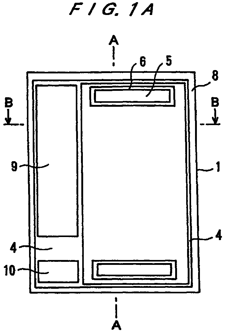
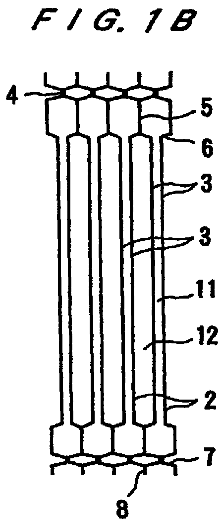
FIGS. 1A, 1B and 1C are schematic views showing an
example of a plate heat exchanger, and FIG. 1A is a front
view, FIG. 1B is a cross-sectional view taken along a line
A-A of FIG. 1A, and FIG. 1C is a cross-sectional view taken
along a line B-B of FIG. 1A.
In FIGS. 1A, 1B and 1C, the plate heat exchanger 1
is constructed by combination of four heat exchange elements
2. The heat exchange element 2 is constructed in such a
state that two plates 3 are piled, and contacting portions
having projections and depressions and peripheral portions 4
are fixed to each other by welding or brazing. Peripheral
rising portions 6 of opening portions 5 at both ends of the
heat exchange elements 2 are piled on each other, and
contacting portions 8 of peripheral protuberances 7 are
piled on each other. These portions 6, 8 are welded or
brazed to combine the four heat exchange elements 2, for
thereby constructing a plate heat exchanger. As a result, a
passage is formed within each of the heat exchange elements
2, and passages are formed between the adjacent heat
exchange elements 2.
A first fluid flows from the opening portions 5
through internal spaces 11 of the heat exchange elements 2.
A vapor, as a second fluid, for example, is introduced from
vapor passages 9 into spaces 12 formed between the adjacent
heat exchange elements 2, and then condensed in the spaces
12 and discharged as a liquid from liquid passages 10.
Separated passages for a second fluid may be provided
outside of the heat exchange elements 2 to absorb a vapor
introduced from the vapor passages 9, and the second fluid
may then be discharged front the liquid passages 10.
As described above, the protuberances are provided
at the peripheries of the heat exchange elements 2, and
brought into contact with each other to seal the heat
exchange elements 2. Hence, external passages as passages
for a second fluid can be formed at a time without use of a
shell.
FIGS. 2A through 2D are schematic views showing
another example of a plate heat exchanger, and FIG. 2A is a
side cross-sectional view, FIG. 2B is a cross-sectional view
taken along a line A-A of FIG. 2A, FIG. 2C is a cross-sectional
view taken along a line B-B of FIG. 2A, and FIG.
2D is a cross-sectional view taken along a line C-C of FIG.
2A.
In a plate heat exchanger shown in FIGS. 2A through
2D, two plate heat exchangers shown in FIGS. 1A, 1B and 1C
are piled in parallel as shown by the reference numerals 1a,
1b to form an integrated unit. Vapor passages 9 for a
second fluid provide a communication between the heat
exchangers 1a and 1b.
The heat exchangers shown in FIGS. 2A through 2D are
applied to an absorber 1b and an evaporator 1a of an
absorption refrigerating machine. The vapor passages 9
communicate with the absorber 1b and the evaporator 1a.
Cold water 13a and cooling water 14a are blocked
therebetween, and outlets for these liquids are also blocked
therebetween, and hence these liquids flow in and flow out
through end surfaces.
In the plate heat exchanger described above, cold
water is introduced into internal spaces 11 of the heat
exchange elements from opening portions 13a in the
evaporator 1a, passed through the spaces 11, cooled thereby,
and discharged from 13b. In external spaces 12 between the
elements, a refrigerant liquid flows down, although this is
not shown. The refrigerant removes heat from the cold water
and is changed into a refrigerant vapor, and this
refrigerant vapor is passed from the external spaces 12
through the vapor passages 9 and reaches the absorber 1b.
In the absorber 1b, cooling water is introduced into
internal spaces 11 from opening portions 14a, passed through
the spaces 11 to cool an absorption solution passing through
external spaces 12, and discharged from 14b. The absorption
solution flowing down through the external spaces 12 absorbs
the refrigerant vapor flowing from the vapor passages 9, and
is then discharged from discharge passages 18 provided below
the vapor passages 9, although this not shown.
The refrigerant that has not evaporated is recovered
in discharge passages 17 for being used as a circulating
refrigerant liquid.
In FIGS. 2A through 2D, the same reference numerals
as those shown in FIGS. 1A, 1B and 1C denote the same parts
or components. The reference numeral 15 denotes a barrier
plate, and the reference numeral 16 denotes shut-off plates.
The plate heat exchanger shown in FIGS. 2A through
2D can similarly be applied to a generator and a condenser
of an absorption refrigerating machine.
As described above, according to the first
embodiment of the present invention, passages curved by
projections and depressions are formed inside and outside of
heat exchange elements composed of one or two types of
components, and the external passages can be formed at a
time without use of a shell. Thus, a complicated plate heat
exchanger with high efficiency of heat exchanging
performance for exchanging heat between two fluids having
different temperatures can be manufactured at low cost from
a small number of components by a simple manufacturing
process.
Next, a plate heat exchanger in a second embodiment
of the present invention will be described below in detail.
As a plate used in the present invention, a plate
having a shape suitable for meeting the following conditions
can be used: When two plates having projections and
depressions are piled on each other to form a space
therebetween, two or four divided sealed spaces are formed
inside of the two plates. Two opening portions are provided
for each of the spaces. When the peripheral portions, the
divided portions, and the opening portions of the plates are
simply piled, they are brought into light contact (i.e.,
line contact) with each other along the whole peripheries.
When a force in a direction of piling is increased, the
contacting portions are changed in shape to be brought into
surface contact with each other. When the force is
increased until the projections and depressions of the
respective plates are brought into contact with each other,
the area of the contact surface is increased, and hence the
peripheries and the divided portions of the plates can be
sealed by brazing.
In the case of brazing, plates are brazed while a
force is being applied in order to bring the plates into
close contact with each other. Accordingly, the
aforementioned plates are preferable because, upon
application of this force, the peripheral portions and the
divided portions of the plates become parallel, and further
the projections and depressions of the plates are brought
into contact with each other.
When two plates described above are piled on each
other while a brazing filler material is laid (applied) at
portions to be brought into contact with each other, a heat
exchange element which has two opening portions in each of
the plates and has two or four independent fluid passages in
an internal space is formed.
The present invention can be applied to not only a
case of brazing, but also a case where a gasket is
interposed between the plates and a force is applied from
the outside, and a case where the plates are sealed by
welding.
The projections and depressions of the plate
according to the present invention can be formed as a
corrugated pattern extending in a predetermined direction,
and hence a complicated passage curved two-dimensionally can
be formed with a relatively simple arrangement.
One of the opening portions at both ends of the
plate is provided with a rising portion, so that positioning
of the plates upon piling can be facilitated by the fitting
of the opening portions. Thus, the two-dimensional
positioning of the plates can naturally be performed by
simply piling the plates on each other. Consequently, the
manufacturing process can be simplified.
The two opening portions provided for the two or
four systems in the internal space of the heat exchange
element are connected to those of the adjacent heat exchange
elements to form fluid passages. Fluids flow separately
through the outside of the heat exchange element
corresponding to these systems in the internal space.
Consequently, a plate heat exchanger capable of
simultaneously exchanging heat between the two or four
fluids can be constructed.
For example, the plate heat exchanger can be applied
to a plate type absorber and a plate type evaporator of an
absorption refrigerating machine, by using cooling water as
an internal fluid in the first system, an absorption
solution as an external fluid in the first system, cold
water as an internal fluid in the second system, and a
refrigerant liquid as an external fluid in the second system.
Further, the plate heat exchanger can be applied to a plate
type generator and a plate type condenser of an absorption
refrigerating machine, by using a heat source fluid (e.g.,
hot water, vapor) as an internal fluid in the first system,
an absorption solution as an external fluid in the first
system, cooling water as an internal fluid in the second
system, and a refrigerant condensate as an external fluid in
the second system. Furthermore, when a four-system plate
heat exchanger in which the plate type absorber and
evaporator and the plate type generator and condenser are
integrated is used, the absorber, the evaporator, the
generator, and the condenser of an absorption refrigerating
machine can be constructed by a single plate heat exchanger.
A plate heat exchanger according to the second
embodiment of the present invention will be described below
in detail with reference to FIGS. 3 through 9.
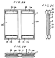
FIGS. 3A, 3B and 3C are schematic views showing an
example of a plate heat exchanger according to the present
invention, and FIG. 3A is a front view, FIG. 3B is a plan
view, and FIG. 3C is a side view.
In FIGS. 3A, 3B and 3C, the reference numeral 3
denotes a plate, and the reference numeral 2 denotes a heat
exchange element. The plate heat exchanger comprises three
heat exchange elements. The heat exchange element 2 has
internal spaces 23 formed into two systems 23a and 23b, and
opening portions 24 (24a, 24b) at an upper side and a lower
side of each of the two systems. Internal spaces of the two
systems are sealed by sealing portions 26. The adjacent
heat exchange elements 2 are connected to each other by open
rising portions 25 of the opening portions 24. External
passages 27 are formed between the adjacent elements and
provided so as to communicate with the exteriors of the
elements.
In the plate heat exchanger of FIGS. 3A, 3B and 3C,
fluids flow through the two systems in the internal spaces
of the heat exchange elements, and also fluids flow through
the two systems in the outside of the heat exchange elements.
Thus, vapor movement occurs between the internal two systems
and the external two systems. Accordingly, two types of
heat exchangers, such as an evaporator and an absorber, or a
generator and a condenser, can be constructed, thereby
achieving compactness.
FIGS. 4A, 4B and 4C are schematic views showing
another example of a plate heat exchanger, and FIG. 4A is a
front view, FIG. 4B is a plan view, and FIG. 4C is a side
view. As shown in these drawings, projections and
depressions 31, 32 can be provided on the surface of the
plate constituting the heat exchange element. The
projections and depressions 32 provided on the sealing
portions 26 between the two systems serve as straightening
vanes for allowing vapor to speedily pass through external
passages 27 outside of the heat exchange elements, and as
eliminators for separating gas and liquid.
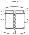
FIG. 5 is a schematic view showing an example of a
construction of the plate heat exchanger, according to the
present invention, which is housed in a shell. As shown in
FIG. 5, spreader pipes 29 for fluids are respectively
mounted on the exteriors of the heat exchange elements 2
corresponding to the internal spaces 23a, 23b of the heat
exchange elements 2 housed in a shell 20.
FIGS. 6A, 6B and 6C show heat exchange elements 2
sealed at the peripheries thereof, as indicated by the
reference numeral 28, instead of using the shell of FIG. 5.
FIG. 6A is a front view, FIG. 6B is a cross-sectional view
taken along a line A-A of FIG. 6A, and FIG. 6C is a cross-sectional
view taken along a line B-B of FIG. 6A. In FIGS.
6A, 6B and 6C, an inlet 33 for introducing a solution or a
refrigerant, for example, is provided in an upper portion.
A solution or a refrigerant is supplied to respective units
by the pipes 29 (see FIG. 5) through the inlet 33, and
outlets 34, 35 for a solution or a refrigerant are
separately provided at a lower portion. When the heat
exchanger is used as a condenser, it is not necessary to
supply a refrigerant liquid.
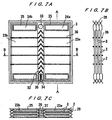
FIGS. 7A, 7B and 7C are schematic views showing
another plate heat exchanger according to the present
invention, and FIG. 7A is a front view, FIG. 7B is a cross-sectional
view taken along a line A-A of FIG. 7A, and FIG.
7C is a cross-sectional view taken along a line B-B of FIG.
7A.
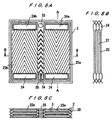
FIGS. 8A, 8B and 8C are schematic views showing
still another plate heat exchanger according to the present
invention, and FIG. 8A is a front view, FIG. 8B is a cross-sectional
view taken along a line A-A of FIG. 8A, and FIG.
8C is a cross-sectional view taken along a line B-B of FIG.
8A.
In the plate heat exchangers shown in FIGS. 3
through 6, the outsides of the passages for the internal
fluids in the two systems of the right and left units
communicate with each other in the right and left direction
to thus form one system. On the other hand, in the plate
heat exchangers shown in FIGS. 7 through 8, the internal
fluids in the right and left units are flowed in the form of
two systems, and the outsides of the passages for the
internal fluids are divided in a vertical direction, and the
divided portions communicate with each other in the right
and left direction. By division of the exteriors through
which a vapor flows, a pressure distribution can be
developed in the vertical direction. If the heat exchanger
thus constructed is applied to an evaporator and an absorber
of an absorption refrigerating machine, for example, then a
multi-stage evaporator and a multi-stage absorber can be
constructed. FIGS. 7 through 8 show heat exchangers having
a four-stage structure.
In the example shown in FIGS. 7A, 7B and 7C, the
divisions into the upper stages and the lower stages are
performed by molded portions 36 of the plates. In the
example shown in FIGS. 8A, 8B and 8C, the divisions into the
upper stages and the lower stages are performed by insertion
of plates 37. In FIGS. 8A, 8B and 8C, the inserted plates
37 serve as not only partition plates, but also eliminators,
and distributors of a liquid flowing downwardly outside of
the plates 3.
The multi-stage configuration is effective for a
generator and a condenser, also.
FIGS. 9A, 9B and 9C are schematic views showing
still another example of a plate heat exchanger according to
the present invention, which is an improved form of the
plate heat exchanger shown in FIGS. 6A, 6B and 6C. In FIGS.
9A, 9B and 9C, four systems, i.e., two right systems and two
left systems, of internal fluids are formed inside of the
plates. Outside of the plates, vapor passages are provided
so as to communicate with the right systems and the left
systems. FIG. 9A is a front view, FIG. 9B is a plan view,
and FIG. 9C is a side view.
The plate heat exchanger shown in FIGS. 9A, 9B and
9C is used as a generator, a condenser, an evaporator, and
an absorber of an absorption refrigerating machine, for
example. A generator 23b and a condenser 23a are arranged
on the left side and the right side of an upper portion,
respectively, while an evaporator 23c and an absorber 23d
are arranged on the right side and the left side of a lower
portion, respectively. However, an evaporator, an absorber,
a condenser, and a generator may be arranged side by side at
the same height.
As described above, in the case where a plate heat
exchanger is constructed so as to have four systems, main
components constituting an absorption refrigerating machine
can be constructed by one type of plate.
As described above, according to the second
embodiment of the present invention, passages in two or four
systems are formed inside and outside of heat exchange
elements composed of one type of plate. Thus, a complicated
plate heat exchanger with high efficiency of heat exchanging
performance for exchanging heat between two or four fluids
having different temperatures can be manufactured at low
cost from a small number of components by a simple
manufacturing process.
Industrial Applicability
The present invention relates to a plate heat
exchanger for exchanging heat between two fluids flowing
alternately through adjacent fluid passages between piled
plates, which is suitable for an evaporator, a low-temperature
generator, a condenser, and the like of a
refrigerating machine using a low-pressure refrigerant.