EP1085213B1 - Wet rotor motorpump with mounting plate - Google Patents
Wet rotor motorpump with mounting plate Download PDFInfo
- Publication number
- EP1085213B1 EP1085213B1 EP00119886A EP00119886A EP1085213B1 EP 1085213 B1 EP1085213 B1 EP 1085213B1 EP 00119886 A EP00119886 A EP 00119886A EP 00119886 A EP00119886 A EP 00119886A EP 1085213 B1 EP1085213 B1 EP 1085213B1
- Authority
- EP
- European Patent Office
- Prior art keywords
- accordance
- base plate
- rotary pump
- pump
- stator
- Prior art date
- Legal status (The legal status is an assumption and is not a legal conclusion. Google has not performed a legal analysis and makes no representation as to the accuracy of the status listed.)
- Expired - Lifetime
Links
Images

Classifications
-
- H—ELECTRICITY
- H02—GENERATION; CONVERSION OR DISTRIBUTION OF ELECTRIC POWER
- H02K—DYNAMO-ELECTRIC MACHINES
- H02K5/00—Casings; Enclosures; Supports
- H02K5/04—Casings or enclosures characterised by the shape, form or construction thereof
- H02K5/12—Casings or enclosures characterised by the shape, form or construction thereof specially adapted for operating in liquid or gas
- H02K5/128—Casings or enclosures characterised by the shape, form or construction thereof specially adapted for operating in liquid or gas using air-gap sleeves or air-gap discs
-
- F—MECHANICAL ENGINEERING; LIGHTING; HEATING; WEAPONS; BLASTING
- F04—POSITIVE - DISPLACEMENT MACHINES FOR LIQUIDS; PUMPS FOR LIQUIDS OR ELASTIC FLUIDS
- F04D—NON-POSITIVE-DISPLACEMENT PUMPS
- F04D13/00—Pumping installations or systems
- F04D13/02—Units comprising pumps and their driving means
- F04D13/06—Units comprising pumps and their driving means the pump being electrically driven
- F04D13/0606—Canned motor pumps
- F04D13/0613—Special connection between the rotor compartments
-
- F—MECHANICAL ENGINEERING; LIGHTING; HEATING; WEAPONS; BLASTING
- F04—POSITIVE - DISPLACEMENT MACHINES FOR LIQUIDS; PUMPS FOR LIQUIDS OR ELASTIC FLUIDS
- F04D—NON-POSITIVE-DISPLACEMENT PUMPS
- F04D29/00—Details, component parts, or accessories
- F04D29/02—Selection of particular materials
- F04D29/026—Selection of particular materials especially adapted for liquid pumps
-
- F—MECHANICAL ENGINEERING; LIGHTING; HEATING; WEAPONS; BLASTING
- F04—POSITIVE - DISPLACEMENT MACHINES FOR LIQUIDS; PUMPS FOR LIQUIDS OR ELASTIC FLUIDS
- F04D—NON-POSITIVE-DISPLACEMENT PUMPS
- F04D29/00—Details, component parts, or accessories
- F04D29/58—Cooling; Heating; Diminishing heat transfer
- F04D29/586—Cooling; Heating; Diminishing heat transfer specially adapted for liquid pumps
- F04D29/588—Cooling; Heating; Diminishing heat transfer specially adapted for liquid pumps cooling or heating the machine
-
- F—MECHANICAL ENGINEERING; LIGHTING; HEATING; WEAPONS; BLASTING
- F04—POSITIVE - DISPLACEMENT MACHINES FOR LIQUIDS; PUMPS FOR LIQUIDS OR ELASTIC FLUIDS
- F04D—NON-POSITIVE-DISPLACEMENT PUMPS
- F04D29/00—Details, component parts, or accessories
- F04D29/60—Mounting; Assembling; Disassembling
- F04D29/62—Mounting; Assembling; Disassembling of radial or helico-centrifugal pumps
- F04D29/628—Mounting; Assembling; Disassembling of radial or helico-centrifugal pumps especially adapted for liquid pumps
-
- H—ELECTRICITY
- H02—GENERATION; CONVERSION OR DISTRIBUTION OF ELECTRIC POWER
- H02K—DYNAMO-ELECTRIC MACHINES
- H02K11/00—Structural association of dynamo-electric machines with electric components or with devices for shielding, monitoring or protection
- H02K11/30—Structural association with control circuits or drive circuits
- H02K11/33—Drive circuits, e.g. power electronics
-
- F—MECHANICAL ENGINEERING; LIGHTING; HEATING; WEAPONS; BLASTING
- F05—INDEXING SCHEMES RELATING TO ENGINES OR PUMPS IN VARIOUS SUBCLASSES OF CLASSES F01-F04
- F05D—INDEXING SCHEME FOR ASPECTS RELATING TO NON-POSITIVE-DISPLACEMENT MACHINES OR ENGINES, GAS-TURBINES OR JET-PROPULSION PLANTS
- F05D2230/00—Manufacture
- F05D2230/60—Assembly methods
- F05D2230/61—Assembly methods using limited numbers of standard modules which can be adapted by machining
-
- F—MECHANICAL ENGINEERING; LIGHTING; HEATING; WEAPONS; BLASTING
- F05—INDEXING SCHEMES RELATING TO ENGINES OR PUMPS IN VARIOUS SUBCLASSES OF CLASSES F01-F04
- F05D—INDEXING SCHEME FOR ASPECTS RELATING TO NON-POSITIVE-DISPLACEMENT MACHINES OR ENGINES, GAS-TURBINES OR JET-PROPULSION PLANTS
- F05D2300/00—Materials; Properties thereof
- F05D2300/10—Metals, alloys or intermetallic compounds
Definitions
- the present invention relates to an electrically operated Centrifugal pump, especially for use in heating and / or Cooling circuits, with a pump housing, the one that Impeller-receiving impeller chamber covered on the front, with a stator surrounded by windings and with one one-piece mounting plate, the one hand the pump housing and on the other hand carries the stator and the means for Has bracket of the pump.
- pumps are known, the supporting part of which Pump housing is one on the electrical side Can forms. With these pumps, the stator is opened held the containment shell.
- This special design is only for comparatively small pumps possible, but none require complex control electronics and only by means of a conventional synchronous or asynchronous drive operate. The possible uses of these pumps is thus limited.
- Such centrifugal pumps are known from e.g. DE-A-1 909 878, US-A-3 433 164.
- the object of the present invention is a centrifugal pump to create that from easy to manufacture components has a modular structure and which is cheaper Manufacturing is characterized by a high degree of reliability.
- the basic idea of the pump according to the invention is one-piece mounting plate on which both the hydraulic and the electrical components can also be installed. Are there those to be mounted directly on the mounting plate essential components on the one hand the pump housing on the hydraulic side and on the other hand the stator with its Stator laminated core on the electrical side.
- This therefore as Chassis-trained mounting plate also allows the complete mounting of the pump on the system.
- the mounting plate is perpendicular to the shaft of the impeller aligned and in particular rotationally symmetrical Base plate that forms a wall of the impeller chamber.
- the mounting plate has a holder for centering and advantageously for the exclusive mounting of the Stator that on the side facing away from the impeller chamber Base plate is molded.
- the stator in the one forming the receptacle Cylinder can be pressed in. So the stator is simple held and simultaneously in the axial and radial directions centered.
- a general advantage of the cylindrical according to the invention Recording is that stators of different lengths are readily available can be used.
- One with such a bracket equipped base plate is universal and can be used for use different pump types.
- the mounting plate according to the invention forms in the manner of a Bearing plate with a surface the engine side wall of the Impeller chamber and serves with its other side, on which the Recording is appropriate, the electrical components as Edition.
- the particular advantage of using this mounting plate Base plate and receptacle is that they are in contact with you Pump medium forms a heat sink through which the control electronics Can dissipate heat. It is advantageous that Control electronics to accommodate in an electronics module and this directly on the side facing away from the impeller chamber Mount the surface of the base plate. This is an optimal one Cooling of the motor and electronics guaranteed. This The advantage is particularly evident in the pumps, their Control electronics a variety of power semiconductors that produce a lot of waste heat.
- the mounting plate with base plate and Holder made of metal to ensure high stability comparatively light weight. It will be out Sheet drawn or die-cast. With the Mounting plate according to the invention can by interchangeable inserts Different mechanical connection variants in the die casting tool will be realized.
- the mounting plate supports the completely modular structure of the pump.
- the invention can be used particularly advantageously in pumps use that of electronically commutated DC motors operate. Can on additional cooling elements because of the advantageous possibility of heat dissipation via the Base plate can be dispensed with.
- the size of the pump can be reduced in that the connector for the electrical supply on the side facing the impeller the base plate is attached. This attachment simplifies the supply line connection.
- the pump structure according to the invention can be particularly advantageous to use with wet rotor pumps, the rotor of which Stator is separated by a containment shell.
- Receiving sleeve with an inward collar provided that the one facing outwards accordingly open bottom of the containment collar is an attachment offers.
- the containment can is simply operated by the hydraulic " Inserted side into the receiving sleeve until both collars come into contact with a sealing ring.
- the hold of the The can is guaranteed by the bearing bracket, which subsequently inserted and in its final locked position the collar of the can with pressure acted upon and thus against the electrical part of the Pump seals.
- Centering the particular from Plastic canister happens advantageously by a cylindrical wall of the Bearing bracket that protrudes into the containment shell.
- the base plate in particular molded plastic housing cover, which the arranged on the electrical side of the base plate Components completely covered.
- This particularly light one Housing cover is advantageously on the outer surface of the the stator receiving cylinder and can by means of locking hooks attached to the base plate or with the base plate be screwed. It is advantageous in the rear To provide a receptacle end face of the cover, the Can fixed and centered.
- this is Pump housing realized in that one in particular Plastic-made housing shell, which parts of the Spiraloder Forms impeller chamber, placed on the base plate and is sealed by a sealing ring.
- the attachment of the Housing shell is advantageously done by means of self-tapping screws. It is particularly beneficial that on the same base plate housing shells with different Arrangements of suction and pressure ports are attached can. It is also advantageous to put the housing shell in with regular intervals on the pitch circle diameter To provide core holes so that the housing shell and so that the pressure port in accordance with customer requirements can be mounted in different directions. Different Arrangements of the sockets can be easily done Implement interchangeable inserts in the injection mold. So you can meet different customer requirements. An optimization of the Spiral space geometry can be achieved using inserts that clamped between the housing shell and the base plate become. Due to the design described, the number of Seals and thus the risk of leaks are reduced.
- the rotating components are mounted axially via an axial plain bearing, the sliding ring on the impeller end face of the stator is held and runs against the bearing bush or over the front of the Impeller that against a the central intake surrounding edge runs.
- the one according to the invention holds and centers Mounting plate with base plate and holder all Components of the pump so that the pump is no more supporting parts. This leads to enormous savings on components and thus on manufacturing costs. simultaneously the reliability of the pump increases.
- the structure of the pump favors axial assembly.
- FIG 1 is an electrically operated centrifugal pump, the Impeller 1 on a shaft 2 with pressed permanent magnetic Rotor 17 is shown.
- the Centrifugal pump has a one-piece mounting plate 3 made of metal, the one on the hydraulic side is the impeller chamber covering plastic shell 4 carries.
- the housing shell 4 has a suction port 7 and a not shown Discharge nozzle on.
- an element 8 a In the spiral room to improve hydraulic properties an element 8 a.
- the mounting plate 3 has on the impeller 1 facing away electrical "side of the base plate 5 a receptacle 9, for holding the stator 10 to the base plate 5 is molded.
- the recording is made from a coaxial Shaft 2 formed on the base plate cylinder, in which the stator is inserted, in particular pressed in.
- On the electrical side is an electronics module 11 in Thermal contact placed on the base plate 5, the one Control electronics for the engine has.
- the electronics module 11 is contacted via a connector 12 which is on the hydraulic side of the base plate 5 is attached.
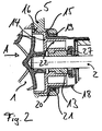
- the base plate 5 has a central, coaxial to the shaft 2 Bore in which the bearing bush 13 ( Figure 2) receiving bearing bracket 14 is held.
- the central one is formed by a sleeve molded onto the base plate 5 15 surround in which the bearing bracket 14 is inserted and is held by locking means 16.
- In the sleeve 15 is also a plastic can 18 held.
- the Holding of the can 18 happens in that the sleeve 15 has an inward collar 19 against the an outwardly directed collar 20 of the arrow A inserted can 18 by means of a sealing ring 21 comes to the plant.
- the collar 20 of the can 18 is from the bearing bracket 14 engaged in the sleeve 15 against the Sealing ring 21 pressurized.
- the bearing bracket 14 has one cylindrical wall 22 on which the containment shell 18 postponed and thus centered.
- the axial bearing of the Shaft 2 occurs through an axial bearing, the sliding ring 27 attacks on the end face of the bearing bush 13.
- FIG. 1 there is a plastic housing cover 23 placed on the all on the electrical side of the base plate 5 arranged components covers and thus the engine cover forms.
- the housing cover 23 lies on the outer surface of the Stator 10 receiving cylinder 9 and is together with the housing shell 4 screwed to the base plate 5.
- On its inner end face has a housing cover 23 Recording 24 in which the can 18 can be inserted.
- On the inside of the containment shell 18 is a sleeve 25 integrally formed, in which the second bearing bush 26 lies. Consequently the housing cover 23 takes over the sealing of the electric motor to the outside world and centers that of the Impeller facing away from the rotor. Will when shedding the electronics also insulates the contacts to the stator, no separate seal on the motor housing is necessary.
- the electronic module is first in the assembly sequence 11 attached and then the stator 10 mounted.
- the already assembled rotor assembly including the Split tops made of plastic is from the pump housing side inserted into the base plate 5.
- the seal between The O-ring takes over wet and dry space in a groove sits in the base plate 5.
- the can 18 is only slightly burdened.
- Reach for axial support Snap hook attached to the bearing bracket 14, in the Base plate 5. The snap hooks can be used with a tool loosened and the rotor assembly dismantled.
Description
Die vorliegende Erfindung betrifft eine elektrisch betriebene Kreiselpumpe, insbesondere für den Einsatz in Heiz- und/oder Kühlkreisläufen, mit einem Pumpengehäuse, das eine das Laufrad aufnehmende Laufradkammer stirnseitig bedeckt, mit einem von Wicklungen umgebenen Stator und mit einer einstückigen Montageplatte, die einerseits das Pumpengehäuse und andererseits den Stator trägt und die Mittel zur Halterung der Pumpe aufweist.The present invention relates to an electrically operated Centrifugal pump, especially for use in heating and / or Cooling circuits, with a pump housing, the one that Impeller-receiving impeller chamber covered on the front, with a stator surrounded by windings and with one one-piece mounting plate, the one hand the pump housing and on the other hand carries the stator and the means for Has bracket of the pump.
Derartige insbesondere als Naßläufer ausgebildete Kreiselpumpen sind seit langem hinlänglich bekannt. Diese Pumpen werden in ihren Einzelkomponenten gefertigt und entsprechend montiert. Neben den Pumpen mit großer Leistung, die wegen ihres Gewichtes auf einem Sockel gelagert werden müssen, gibt es kleine Pumpen, z.B. Brauchwasserpumpen, die direkt an dem System, das sie versorgen, angebracht werden können. Meist dient als tragendes Element ein entsprechend stabil konzipiertes Pumpengehäuse, das die anderen Komponenten aufnimmt und das mit Befestigungsmitteln am System, beispielsweise über einen Anschlußflansch, gehalten wird. Such trained in particular as a wet runner Centrifugal pumps have long been known. This Pumps are manufactured in their individual components and assembled accordingly. In addition to the pumps with great performance, which are stored on a base because of their weight there are small pumps, e.g. Domestic water pumps, the can be attached directly to the system they supply can. Usually serves as a supporting element stable pump housing that the others Takes up components and that with fasteners on System, for example via a connecting flange becomes.
Außerdem sind Pumpen bekannt, deren tragendes Teil das Pumpengehäuse ist, das auf der elektrischen Seite einen Spalttopf ausbildet. Bei diesen Pumpen wird der Stator auf dem Spalttopf gehalten. Diese besondere Bauart ist nur bei vergleichsweise kleinen Pumpen möglich, die zudem keiner aufwendigen Ansteuerelektronik bedürfen und lediglich mittels eines herkömmlichen Synchron- oder Asynchronantriebes betrieben werden. Die Einsatzmöglichkeiten dieser Pumpen ist somit beschränkt. Solche Kreiselpumpen sind bekannt aus z.B. DE-A-1 909 878, US-A-3 433 164.In addition, pumps are known, the supporting part of which Pump housing is one on the electrical side Can forms. With these pumps, the stator is opened held the containment shell. This special design is only for comparatively small pumps possible, but none require complex control electronics and only by means of a conventional synchronous or asynchronous drive operate. The possible uses of these pumps is thus limited. Such centrifugal pumps are known from e.g. DE-A-1 909 878, US-A-3 433 164.
Generell ist es bei den bekannten Pumpen nachteilig, daß sie wegen der großen Zahl der Einzelkomponenten mit einem vergleichsweise hohen Montageaufwand gefertigt werden, was zu einer Erhöhung der Herstellungskosten beiträgt. Die bekannten Pumpen weisen außerdem eine Vielzahl von Metallteilen auf, die nach der Herstellung zunächst einer mechanischen Nacharbeit bedürfen, wodurch die Herstellungskosten belastet werden. In ihrer Konstruktion sind die herkömmlichen Pumpen auch auf eine bestimmte Bauart und Leistung ausgelegt, so daß für jedes Einsatzgebiet eine separate Baugröße vorgesehen werden muß. Ein weiterer Nachteil ist, daß die Pumpen unkomfortabel zu warten und zu reparieren sind, da die kritischen Komponenten schwer zugänglich sind.In general, it is disadvantageous in the known pumps that they because of the large number of individual components with one comparatively high assembly costs, which leads to contributes to an increase in manufacturing costs. The well-known Pumps also have a variety of metal parts, which after the manufacture is initially a mechanical one Rework is required, which burdens the manufacturing costs become. The construction of the conventional pumps also designed for a certain type and performance, so that a separate size is provided for each area of application must become. Another disadvantage is that the pumps are uncomfortable to maintain and repair because the critical components are difficult to access.
Aufgabe der vorliegenden Erfindung ist es, eine Kreiselpumpe zu schaffen, die aus einfach herzustellenden Komponenten modular aufgebaut ist und die sich bei kostengünstiger Fertigung durch ein hohes Maß an Zuverlässigkeit auszeichnet.The object of the present invention is a centrifugal pump to create that from easy to manufacture components has a modular structure and which is cheaper Manufacturing is characterized by a high degree of reliability.
Diese Aufgabe wird durch eine Kreiselpumpe nach Anspruch 1 gelöst.This object is achieved by a centrifugal pump according to claim 1 solved.
Grundlegende Idee der erfindungsgemäßen Pumpe ist die einteilige Montageplatte, an der sowohl die hydraulischen als auch die elektrischen Komponenten montiert werden. Dabei sind die unmittelbar auf der Montageplatte zu montierenden wesentlichen Komponenten einerseits das Pumpengehäuse auf der hydraulischen Seite und andererseits der Stator mit seinem Statorblechpaket auf der elektrischen Seite. Diese somit als Chassis ausgebildete Montageplatte erlaubt außerdem die komplette Halterung der Pumpe am System. Erfindungsgemäß hat die Montageplatte eine senkrecht zur Welle des Laufrades ausgerichtete und insbesondere rotationssysmmetrische Basisplatte, die eine Wand der Laufradkammer bildet. Zudem hat die Montageplatte eine Aufnahme zur Zentrierung und vorteilhafterweise zur ausschließlichen Halterung des Stators, die an die der Laufradkammer abgewandten Seite der Basisplatte angeformt ist. In einer vorteilhaften Ausführungsform ist der Stator in den die Aufnahme bildenden Zylinder einpreßbar. So ist der Stator auf einfache Weise gehalten und gleichzeitig in axialer und radialer Richtung zentriert.The basic idea of the pump according to the invention is one-piece mounting plate on which both the hydraulic and the electrical components can also be installed. Are there those to be mounted directly on the mounting plate essential components on the one hand the pump housing on the hydraulic side and on the other hand the stator with its Stator laminated core on the electrical side. This therefore as Chassis-trained mounting plate also allows the complete mounting of the pump on the system. According to the invention the mounting plate is perpendicular to the shaft of the impeller aligned and in particular rotationally symmetrical Base plate that forms a wall of the impeller chamber. moreover the mounting plate has a holder for centering and advantageously for the exclusive mounting of the Stator that on the side facing away from the impeller chamber Base plate is molded. In an advantageous Embodiment is the stator in the one forming the receptacle Cylinder can be pressed in. So the stator is simple held and simultaneously in the axial and radial directions centered.
Ein genereller Vorteil der erfindungsgemäßen zylindrischen Aufnahme ist, daß ohne weiteres verschieden lange Statoren einsetzbar sind. Eine mit einer derartigen Halterung ausgestattete Basisplatte ist universell und läßt sich für verschiedene Pumpentypen einsetzen.A general advantage of the cylindrical according to the invention Recording is that stators of different lengths are readily available can be used. One with such a bracket equipped base plate is universal and can be used for use different pump types.
Die erfindungsgemäße Montageplatte bildet in der Art eines Lagerschildes mit einer Fläche die motorseitige Wand der Laufradkammer und dient mit ihrer anderen Seite, auf der die Aufnahme angebracht ist, den elektrischen Komponenten als Auflage. Der besondere Vorteil dieser Montageplatte mit Basisplatte und Aufnahme ist, daß sie in Ihrem Kontakt zum Pumpmedium eine Wärmesenke bildet, über die die Ansteuerelektronik Wärme abführen kann. Dabei ist es vorteilhaft, die Ansteuerelektronik in einem Elektronikmodul unterzubringen und dieses direkt auf der der Laufradkammer abgewandten Fläche der Basisplatte zu montieren. Somit ist eine optimale Kühlung des Motors und der Elektronik gewährleistet. Dieser Vorteil kommt vor allem bei den Pumpen zur Geltung, deren Steuerelektronik eine Vielzahl an Leistungshalbleitern aufweist, die viel Abwärme produzieren.The mounting plate according to the invention forms in the manner of a Bearing plate with a surface the engine side wall of the Impeller chamber and serves with its other side, on which the Recording is appropriate, the electrical components as Edition. The particular advantage of using this mounting plate Base plate and receptacle is that they are in contact with you Pump medium forms a heat sink through which the control electronics Can dissipate heat. It is advantageous that Control electronics to accommodate in an electronics module and this directly on the side facing away from the impeller chamber Mount the surface of the base plate. This is an optimal one Cooling of the motor and electronics guaranteed. This The advantage is particularly evident in the pumps, their Control electronics a variety of power semiconductors that produce a lot of waste heat.
Vorteilhafterweise wird die Montageplatte mit Basisplatte und Aufnahme aus Metall gefertigt, um eine hohe Stabilität bei vergleichsweise geringem Gewicht zu erhalten. Sie wird aus Blech gezogen oder im Druckgußverfahren hergestellt. Mit der erfindungsgemäßen Montageplatte können durch Wechseleinsätze im Druckgußwerkzeug unterschiedliche mechanische Anschlußvarianten realisiert werden. Die Montageplatte unterstützt dabei den vollständig modularen Aufbau der Pumpe.The mounting plate with base plate and Holder made of metal to ensure high stability comparatively light weight. It will be out Sheet drawn or die-cast. With the Mounting plate according to the invention can by interchangeable inserts Different mechanical connection variants in the die casting tool will be realized. The mounting plate supports the completely modular structure of the pump.
Besonders vorteilhaft läßt sich die Erfindung bei Pumpen einsetzen, die von elektronisch kommutierten Gleichstrommotoren betrieben werden. Auf zusätzliche Kühlelemente kann wegen der vorteilhaften Möglichkeit der Wärmeabfuhr über die Basisplatte verzichtet werden. Die Baugröße der Pumpe kann dadurch reduziert werden, daß der Anschlußstecker für die elektrische Versorgung auf der dem Laufrad zugewandten Seite der Basisplatte angebracht ist. Diese Anbringung vereinfacht den Anschluß Versorgungsleitung.The invention can be used particularly advantageously in pumps use that of electronically commutated DC motors operate. Can on additional cooling elements because of the advantageous possibility of heat dissipation via the Base plate can be dispensed with. The size of the pump can be reduced in that the connector for the electrical supply on the side facing the impeller the base plate is attached. This attachment simplifies the supply line connection.
Vorteilhafterweise ist die insbesondere rotationssymmetrische Basisplatte mit einer koaxial zur Laufradwelle ausgerichteten zentralen Bohrung versehen, die zur Aufnahme des Lagers dient. Statt die Lagerbuchse direkt in dieser Bohrung zu halten ist es vorteilhaft, in die Bohrung einen insbesondere aus Kunststoff gefertigten Lagerträger einzusetzen, der seinerseits eine Bohrung zur Aufnahme der Lagerbuchse aufweist. Auf diese Weise kann die zentrale Bohrung ausreichend groß konzipiert werden, um ein Durchstecken des Rotors und eines den Rotor umgebenden Spalttopfes zu ermöglichen. Die erfindungsgemäße zentrale Bohrung trägt so zur Vereinfachung der Montage bei. Zur Führung und zur Halterung des Lagerträgers ist es vorteilhaft, die zentrale Bohrung auf der elektrischen" Seite mit einer umgebenden Aufnahmehülse zu versehen, in die der Lagerträger eingepreßt ist und/oder durch Rastmittel gehalten ist.It is advantageously particularly rotationally symmetrical Base plate with a coaxial to the impeller shaft central bore provided for receiving the bearing serves. Instead of the bearing bush directly in this hole it is advantageous to hold one in particular in the bore to use plastic bearing bracket, the in turn a hole for receiving the bearing bush having. In this way, the central hole be designed large enough to be able to insert the Rotor and a containment shell surrounding the rotor enable. The central bore according to the invention thus bears to simplify assembly. For leadership and for Mounting the bearing bracket, it is advantageous to the central Hole on the electrical "side with a surrounding one To provide receiving sleeve into which the bearing bracket is pressed is and / or is held by locking means.
Der erfindungsgemäße Pumpenaufbau läßt sich besonders vorteilhaft bei Naßläuferpumpen einsetzen, deren Rotor vom Stator durch einen Spalttopf getrennt ist. Um die Montage derartiger Pumpen zu vereinfachen, ist es vorteilhaft die Aufnahmehülse mit einem nach Innen gerichteten Kragen zu versehen, der einem entsprechend nach Außen gerichteten am offenen Boden des Spalttopfes befindlichen Kragen eine Anlage bietet. Der Spalttopf wird einfach von der hydraulischen" Seite in die Aufnahmehülse eingeschoben bis beide Kragen vermittels eines Dichtringes zur Anlage kommen. Der Halt des Spalttopfes wird durch den Lagerträger gewährleistet, der nachfolgend eingeschoben wird und in seiner endgültigen eingerasteten Position den Kragen des Spalttopfes mit Druck beaufschlagt und somit gegenüber dem elektrischen Teil der Pumpe abdichtet. Die Zentrierung des insbesondere aus Kunststoff gefertigten Spalttopfes geschieht dabei vorteilhafterweise durch eine zylindrische Wandung des Lagerträgers, die in den Spalttopf hineinragt.The pump structure according to the invention can be particularly advantageous to use with wet rotor pumps, the rotor of which Stator is separated by a containment shell. To the assembly To simplify such pumps, it is advantageous Receiving sleeve with an inward collar provided that the one facing outwards accordingly open bottom of the containment collar is an attachment offers. The containment can is simply operated by the hydraulic " Inserted side into the receiving sleeve until both collars come into contact with a sealing ring. The hold of the The can is guaranteed by the bearing bracket, which subsequently inserted and in its final locked position the collar of the can with pressure acted upon and thus against the electrical part of the Pump seals. Centering the particular from Plastic canister happens advantageously by a cylindrical wall of the Bearing bracket that protrudes into the containment shell.
Vorteilhafterweise ist auf die Basisplatte ein, insbesondere aus Kunststoff geformter, Gehäusedeckel aufsetzbar, der die auf der elektrischen Seite der Basisplatte angeordneten Komponenten vollständig abdeckt. Dieser besonders leichte Gehäusedeckel liegt vorteilhafterweise an der Außenfläche des den Stator aufnehmenden Zylinders an und kann durch Rasthaken an der Basisplatte befestigt werden oder mit der Basisplatte verschraubt werden. Es ist vorteilhaft, in der hinteren Stirnseite des Deckels eine Aufnahme vorzusehen, die den Spalttopf fixiert und zentriert.Advantageously, is on the base plate, in particular molded plastic housing cover, which the arranged on the electrical side of the base plate Components completely covered. This particularly light one Housing cover is advantageously on the outer surface of the the stator receiving cylinder and can by means of locking hooks attached to the base plate or with the base plate be screwed. It is advantageous in the rear To provide a receptacle end face of the cover, the Can fixed and centered.
In einer zu bevorzugenden Ausführungsform wird das Pumpengehäuse dadurch realisiert, daß eine insbesondere aus Kunststoff gefertigte Gehäuseschale, welche Teile der Spiraloder Laufradkammer bildet, auf die Basisplatte aufgesetzt und über einen Dichtring abgedichtet ist. Die Befestigung der Gehäuseschale geschieht vorteilhafterweise mittels selbstschneidender Schrauben. Es ist besonders vorteilhaft, daß an dieselbe Basisplatte Gehäuseschalen mit verschiedenen Anordnungen von Saug- und Druckstutzen angebracht werden können. Es ist auch vorteilhaft, die Gehäuseschale in regelmäßigen Abständen auf dem Teilkreisdurchmesser mit Kernbohrungen zu versehen, so daß sich die Gehäuseschale und damit der Druckstutzen dem Kundenwunsch entsprechend in verschiedenen Richtungen montieren läßt. Unterschiedliche Anordnungen der Stutzen lassen sich einfach durch Wechseleinsätze im Spritzwerkzeug realisieren. So lassen sich unterschiedliche Kundenwünsche erfüllen. Eine Optimierung der Spiralraumgeometrie läßt sich über Einsätze erreichen, die zwischen die Gehäuseschale und die Basisplatte geklemmt werden. Durch die beschriebene Bauweise wird die Zahl der Dichtungen und damit die Gefahr von Leckagen reduziert.In a preferred embodiment, this is Pump housing realized in that one in particular Plastic-made housing shell, which parts of the Spiraloder Forms impeller chamber, placed on the base plate and is sealed by a sealing ring. The attachment of the Housing shell is advantageously done by means of self-tapping screws. It is particularly beneficial that on the same base plate housing shells with different Arrangements of suction and pressure ports are attached can. It is also advantageous to put the housing shell in with regular intervals on the pitch circle diameter To provide core holes so that the housing shell and so that the pressure port in accordance with customer requirements can be mounted in different directions. different Arrangements of the sockets can be easily done Implement interchangeable inserts in the injection mold. So you can meet different customer requirements. An optimization of the Spiral space geometry can be achieved using inserts that clamped between the housing shell and the base plate become. Due to the design described, the number of Seals and thus the risk of leaks are reduced.
Die axiale Lagerung der rotierenden Komponenten geschieht über ein axiales Gleitlager, dessen Gleitring an der laufradseitigen Stirnfläche des Stators gehalten ist und gegen die Lagerbuchse läuft oder über die Stirnseite des Laufrades, das gegen eine die zentrale Ansaugöffnung umgebende Kante läuft. The rotating components are mounted axially via an axial plain bearing, the sliding ring on the impeller end face of the stator is held and runs against the bearing bush or over the front of the Impeller that against a the central intake surrounding edge runs.
In der günstigsten Form hält und zentriert die erfindungsgemäße Montageplatte mit Basisplatte und Aufnahme sämtliche Komponenten der Pumpe, so daß die Pumpe keiner weiteren tragenden Teile bedarf. Das führt zu einer enormen Einsparung an Bauteilen und damit an Herstellungskosten. Gleichzeitig steigt die Zuverlässigkeit der Pumpe. Der Aufbau der Pumpe begünstigt die axiale Montage.In the most favorable form, the one according to the invention holds and centers Mounting plate with base plate and holder all Components of the pump so that the pump is no more supporting parts. This leads to enormous savings on components and thus on manufacturing costs. simultaneously the reliability of the pump increases. The structure of the pump favors axial assembly.
Wegen des einfachen, kompakten und gleichzeitig modularen Aufbaus der Pumpen lassen sich diese besonders gut im Kühlkreislauf von Kraftfahrzeugen einsetzen. Dieses Einsatzgebiet wird zudem dadurch begünstigt, daß sich die erfindungsgemäßen Pumpen wegen der Reduzierung der Bauteile besonders kostengünstig fertigen lassen. Die geringe Zahl der Bauteile geht dabei mit einer entsprechenden Erhöhung der Betriebssicherheit einher. Die Fertigungskosten werden zudem durch das einfache Zusammenfügen der Bauteile Montage in einer Richtung gesenkt. Die Wartung und Reparatur der Pumpen ist entsprechend einfach.Because of the simple, compact and at the same time modular The construction of the pumps is particularly easy in the Use the cooling circuit of motor vehicles. This Application area is also favored by the fact that the Pumps according to the invention because of the reduction in components can be manufactured particularly cost-effectively. The small number of Components goes with a corresponding increase in Operational security. The manufacturing costs are also by simply assembling the components in lowered in one direction. Maintenance and repair of the pumps is accordingly simple.
Eine besondere Ausführungsform der erfindungsgemäßen Kreiselpumpe ist in der Figuren 1 und 2 dargestellt und wird im folgenden näher beschrieben. Es zeigen:
- Figur 1:
- eine erfindungsgemäße Pumpe und
- Figur 2:
- eine Detailansicht der erfindungsgemäßen Pumpe.
- Figure 1:
- a pump according to the invention and
- Figure 2:
- a detailed view of the pump according to the invention.
In Figur 1 ist eine elektrisch betriebene Kreiselpumpe, deren
Laufrad 1 auf einer Welle 2 mit aufgepreßtem permanentmagnetischem
Rotor 17 gehalten ist, dargestellt. Die
Kreiselpumpe hat eine einteilige Montageplatte 3 aus Metall,
die auf ihrer hydraulischen" Seite eine die Laufradkammer
abdeckende aus Kunststoff gefertigte Gehäuseschale 4 trägt. In Figure 1 is an electrically operated centrifugal pump, the
Dabei ist die auf die senkrecht zur Welle 2 ausgerichtete
Basisplatte 5 der Montageplatte 3 aufgesetzte Gehäuseschale 4
über einen Dichtring 6 abgedichtet. Die Gehäuseschale 4 weist
einen Saugstutzen 7 und einen nicht dargestellten
Druckstutzen auf. Im Spiralraum liegt zur Verbesserung der
hydraulischen Eigenschaften ein Element 8 ein.Here is that oriented perpendicular to the shaft 2
Die Montageplatte 3 weist auf der dem Laufrad 1 abgewandten
elektrischen" Seite der Basisplatte 5 eine Aufnahme 9 auf,
die zur Halterung des Stators 10 an die Basisplatte 5
angeformt ist. Die Aufnahme wird dabei von einem koaxial zur
Welle 2 an die Basisplatte angeformten Zylinder gebildet, in
den der Stator eingesetzt, insbesondere eingepreßt, ist. Auf
der elektrischen Seite ist ein Elektronikmodul 11 in
Wärmekontakt auf die Basisplatte 5 aufgesetzt, das eine
Steuerelektronik für den Motor aufweist. Das Elektronikmodul
11 wird über einen Anschlußstecker 12 kontaktiert, der auf
der hydraulischen Seite der Basisplatte 5 anbracht ist.The mounting
Die Basisplatte 5 weist eine zur Welle 2 koaxiale zentrale
Bohrung auf, in der ein die Lagerbuchse 13 (Figur 2)
aufnehmender Lagerträger 14 gehalten ist. Die zentrale
Bohrung ist von einer an die Basisplatte 5 angeformte Hülse
15 umgeben, in welcher der Lagerträger 14 eingesetzt und
durch Rastmittel 16 gehalten ist. In der Hülse 15 ist zudem
ein aus Kunststoff geformter Spalttopf 18 gehalten. Die
Halterung des Spalttopfes 18 geschieht dadurch, daß die Hülse
15 einen nach Innen gerichteten Kragen 19 aufweist gegen den
ein nach Außen gerichteter Kragen 20 des in Pfeilrichtung A
eingeschobenen Spalttopfes 18 vermittels eines Dichtringes 21
zur Anlage kommt. Der Kragen 20 des Spalttopfes 18 wird von
dem in der Hülse 15 eingerasteten Lagerträger 14 gegen den
Dichtring 21 druckbeaufschlagt. Der Lagerträger 14 hat eine
zylindrische Wandung 22, auf die der Spalttopf 18
aufgeschoben und damit zentriert ist. Die axiale Lagerung der
Welle 2 geschieht durch ein Axiallager, dessen Gleitring 27
an der Stirnseite der Lagerbuchse 13 angreift.The
Wie in Figur 1 zu erkennen, ist auf die Basisplatte 5 ein,
aus Kunststoff geformter Gehäusedeckel 23 aufgesetzt, der
alle auf der elektrischen Seite der Basisplatte 5
angeordneten Komponenten abdeckt und damit den Motordeckel
bildet. Der Gehäusedeckel 23 liegt an der Außenfläche des den
Stator 10 aufnehmenden Zylinders 9 an und wird gemeinsam mit
der Gehäuseschale 4 an der Basisplatte 5 verschraubt. An
seiner inneren Stirnseite weist der Gehäusedeckel 23 eine
Aufnahme 24 auf, in die der Spalttopf 18 einsetzbar ist. An
die Innenseite des Spalttopfes 18 ist eine Hülse 25
angeformt, in der die zweite Lagerbuchse 26 einliegt. Somit
übernimmt der Gehäusedeckel 23 die Abdichtung des
elektrischen Motors zur Außenwelt und zentriert die vom
Laufrad abgewendete Seite des Rotors. Werden beim Vergießen
der Elektronik gleich die Kontakte zum Stator mitisoliert,
ist keine separate Dichtung am Motorgehäuse nötig.As can be seen in FIG. 1, there is a
plastic housing cover 23 placed on the
all on the electrical side of the
In der Montagereihenfolge wird zunächst das Elektronikmodul 11 befestigt und anschließend der Stator 10 montiert. Bei der Montage des Stators wird gleichzeitig der Kontakt 28 zwischen Stator 10 und Elektronikmodul 11 beispielsweise über Schneidklemmkontakte hergestellt. Nun kann die Elektronik geprüft werden.The electronic module is first in the assembly sequence 11 attached and then the stator 10 mounted. In the Assembly of the stator is the contact 28 between Stator 10 and electronics module 11, for example Insulation displacement contacts made. Now the electronics can being checked.
Die bereits montierte Rotorbaugruppe inklusive des
Spalttopofes aus Kunststoff wird von der Pumpengehäuseseite
in die Basisplatte 5 eingeschoben. Die Abdichtung zwischen
Naß- und Trockenraum übernimmt der O-Ring, der in einer Nut
in der Basisplatte 5 sitzt. Durch die metallische Abstützung
um den O-Ring und dem Spalttopf 18 werden auf den Spalttopf
18 wirkende Druckkräfte optimal aufgenommen. Der Spalttopf 18
wird nur gering belastet. Zur axialen Abstützung greifen
Schnapphaken, angebracht am Lagerträger 14, in die
Basisplatte 5. Mit einem Werkzeug können die Schnapphaken
gelöst und die Rotorbaugruppe demontiert werden.The already assembled rotor assembly including the
Split tops made of plastic is from the pump housing side
inserted into the
Mit diesem Aufbau können unterschiedliche Pumpenleistungen realisiert werden. Dieses kann geschehen durch Verwendung eines anderen Stators und/oder Rotorbaugruppe. Zum anderen kann durch Verwendung eines anderen Laufrades ggf. in Kombination mit einem anderen Kunststoffpumpengehäuseteil der geforderte Betriebspunkt je nach Kundenwunsch optimal eingestellt werden. In jedem Fall können eine Vielzahl von Bauteilen verwendet werden.With this structure, different pump capacities can will be realized. This can be done through use another stator and / or rotor assembly. On the other hand can be changed if necessary by using a different impeller Combination with another plastic pump housing part of the required operating point optimally according to customer requirements can be set. In any case, a variety of Components are used.
Claims (16)
- Electrically driven rotary pump, particularly one for use in heating and/or cooling circuits, with a pump housing (4) that covers an end face of a rotor chamber that takes up a rotor, with a stator (10) surrounded by windings and with a single-piece mounting plate (3) that carries both the pump housing (4) and the stator (10) and that has means of holding the pump, whereby the single-piece mounting plate (3) has a base plate (5) aligned vertically in relation to the shaft (2) of the rotor (1), the said base plate (5) forming the wall of the rotor chamber, and the mounting plate has an uptake means (9), for centring the stator (10), on which the side of the base plate (5) that faces away from the rotor chamber is formed.
- Rotary pump in accordance with claim 1,
characterized in that the uptake means is formed by a cylinder (9), into which the stator (10) can be inserted, particularly by forcing it in, the said cylinder (9) being formed, coaxial with the rotor shaft (2), on the base plate (5). - Rotary pump in accordance with claim 2,
characterized in that the mounting plate (3) is drawn or die cast from metal, particularly from sheet metal. - Rotary pump in accordance with one of the preceding claims,
characterized in that the uptake means forms the holding means for the stator. - Rotary pump in accordance with one of the preceding claims,
characterized in that an electronics module (11), that has, in particular, control electronic means with output semi-conductors, whereby the electronics module (11) is held on the side, of the base plate (5) with heat contact and forming a heat sink, facing away from the rotor (1). - Rotary pump in accordance with one of the preceding claims,
characterized in that the base plate (5) has a central boring, that is coaxial in relation to the rotor shaft, a bearing flange (14) that takes up a bearing (13) being held in the central boring. - Rotary pump in accordance with claim 6,
characterized in that the central boring is surrounded by a bushing (15) that is formed on the base plate (5) and in which the bearing flange (14) is held and/or forced by stop means. - Rotary pump in accordance with one of the preceding claims,
characterized in that a gap casing (18), made in particular of plastic or other synthetic material, is held in the bushing (15). - Rotary pump in accordance with one of the preceding claims,
characterized in that the bushing (15) has a collet (19) that is directed inwards, against which a collet (20), of the gap casing (18), that is directed outwards, comes to lie, particularly by means of a sealing ring (21), whereby the gap casing (18) has pressure applied to it by the bearing flange (14). - Rotary pump in accordance with one of the preceding claims,
characterized in that a cylindrical surface (22) of the bearing flange centres the gap casing. - Rotary pump in accordance with one of the preceding claims,
characterized in that the housing cover (23) made, in particular, from plastic or other synthetic material, can be set on the base plate (5), the said housing cover (23) covering the components disposed on the electrical side of the base plate (5). - Rotary pump in accordance with claim 1,
characterized in that the housing cover (23) lies on the outer surface of the cylinder (9) that takes up the stator (10). - Rotary pump in accordance with one of the preceding claims,
characterized in that the pump housing has a cover (4) that is set on the base plate (5) and that is sealed by means of a sealing ring (6). - Rotary pump in accordance with one of the preceding claims,
characterized in that the driving occurs by means of an electronically commutated DC motor. - Rotary pump in accordance with one of the preceding claims,
characterized in that the connection socket (12) for the electricity supply is on the side of the base plate (5) facing the rotor (1). - Rotary pump in accordance with one of the preceding claims for conveying the medium in the cooling circuit of a vehicle.
Applications Claiming Priority (2)
| Application Number | Priority Date | Filing Date | Title |
|---|---|---|---|
| DE19943862A DE19943862A1 (en) | 1999-09-13 | 1999-09-13 | Wet rotor pump with mounting plate |
| DE19943862 | 1999-09-13 |
Publications (3)
| Publication Number | Publication Date |
|---|---|
| EP1085213A2 EP1085213A2 (en) | 2001-03-21 |
| EP1085213A3 EP1085213A3 (en) | 2001-09-19 |
| EP1085213B1 true EP1085213B1 (en) | 2004-11-17 |
Family
ID=7921887
Family Applications (1)
| Application Number | Title | Priority Date | Filing Date |
|---|---|---|---|
| EP00119886A Expired - Lifetime EP1085213B1 (en) | 1999-09-13 | 2000-09-13 | Wet rotor motorpump with mounting plate |
Country Status (2)
| Country | Link |
|---|---|
| EP (1) | EP1085213B1 (en) |
| DE (2) | DE19943862A1 (en) |
Cited By (2)
| Publication number | Priority date | Publication date | Assignee | Title |
|---|---|---|---|---|
| CN104411977A (en) * | 2012-06-22 | 2015-03-11 | 威乐欧洲股份公司 | Motorized centrifugal pump with a rotary seal |
| US10935028B2 (en) | 2016-06-20 | 2021-03-02 | Pierburg Pump Technology Gmbh | Electric fluid pump for a motor vehicle |
Families Citing this family (17)
| Publication number | Priority date | Publication date | Assignee | Title |
|---|---|---|---|---|
| JP4034077B2 (en) * | 2002-01-30 | 2008-01-16 | カルソニックカンセイ株式会社 | Cand pump |
| DE10221843B4 (en) * | 2002-05-16 | 2004-12-30 | Minebea Co., Ltd. | Electric motor for use as a pump motor and pump |
| DE102004003400B4 (en) * | 2004-01-23 | 2012-08-23 | Ksb Aktiengesellschaft | A centrifugal pump unit |
| GB2418072B (en) * | 2004-09-14 | 2008-05-07 | Dana Automotive Ltd | Pump assembly |
| DE102006027001A1 (en) * | 2006-06-08 | 2007-12-13 | Oase Gmbh | Water pump for especially ponds, aquariums, fountains and the like |
| DE102007033168A1 (en) * | 2007-07-17 | 2009-01-22 | Wilo Ag | Fixing a radial bearing in the containment shell |
| DE102008019608A1 (en) * | 2008-04-18 | 2009-10-22 | Continental Automotive Gmbh | Isolation support for a stator of an electric motor for driving liquid pumps |
| PL2607710T3 (en) * | 2011-12-23 | 2015-08-31 | Grundfos Holding As | Wet running circulation pump |
| DE102013004340A1 (en) * | 2013-03-14 | 2014-09-18 | Wilo Se | Plain bearing mounting in a centrifugal pump unit |
| DE102013020387A1 (en) * | 2013-12-10 | 2015-06-11 | Wilo Se | Wet rotor motor pump |
| DE202015105245U1 (en) * | 2015-10-05 | 2017-01-09 | Ebm-Papst St. Georgen Gmbh & Co. Kg | electric motor |
| CN106368954B (en) * | 2016-11-29 | 2018-07-06 | 南通富莱克流体装备有限公司 | Slurry delivery pump |
| ES2897758T3 (en) * | 2017-03-31 | 2022-03-02 | Grundfos Holding As | pump assembly |
| EP3382206B1 (en) * | 2017-03-31 | 2020-12-16 | Grundfos Holding A/S | Pump assembly |
| CN112262517A (en) | 2018-06-08 | 2021-01-22 | 皮尔伯格泵技术有限责任公司 | Sealed electric motor |
| CN114109853B (en) * | 2020-08-27 | 2023-01-24 | 芜湖美的厨卫电器制造有限公司 | Water pump and water heater with same |
| DE102021103610A1 (en) * | 2021-02-16 | 2022-08-18 | Ebm-Papst Mulfingen Gmbh & Co. Kg | Electric motor, electronics module for an electric motor, method for setting a reference voltage and method for manufacturing a large number of electric motors |
Family Cites Families (6)
| Publication number | Priority date | Publication date | Assignee | Title |
|---|---|---|---|---|
| US3433164A (en) * | 1967-03-03 | 1969-03-18 | Buffalo Forge Co | Motor-pump unit |
| DE1909878A1 (en) * | 1969-02-27 | 1970-09-17 | Hanning Elektro Werke | Heating circulation pump for combined gravity and pump operation |
| US4234293A (en) * | 1979-03-27 | 1980-11-18 | Dresser Industries, Inc. | Axial balancing system for motor driven pumps |
| US5494417A (en) * | 1994-08-03 | 1996-02-27 | Little Giant Pump Company | Shaft sealing and alignment assembly for a pump assembly |
| DE19527879A1 (en) * | 1995-07-29 | 1997-01-30 | Lutz Pumpen Gmbh & Co Kg | Electric motor, in particular drive motor for a drum or container pump |
| DE19545561A1 (en) * | 1995-12-07 | 1997-06-12 | Pierburg Ag | Pump motor unit |
-
1999
- 1999-09-13 DE DE19943862A patent/DE19943862A1/en not_active Withdrawn
-
2000
- 2000-09-13 DE DE50008650T patent/DE50008650D1/en not_active Expired - Lifetime
- 2000-09-13 EP EP00119886A patent/EP1085213B1/en not_active Expired - Lifetime
Cited By (2)
| Publication number | Priority date | Publication date | Assignee | Title |
|---|---|---|---|---|
| CN104411977A (en) * | 2012-06-22 | 2015-03-11 | 威乐欧洲股份公司 | Motorized centrifugal pump with a rotary seal |
| US10935028B2 (en) | 2016-06-20 | 2021-03-02 | Pierburg Pump Technology Gmbh | Electric fluid pump for a motor vehicle |
Also Published As
| Publication number | Publication date |
|---|---|
| DE50008650D1 (en) | 2004-12-23 |
| EP1085213A3 (en) | 2001-09-19 |
| EP1085213A2 (en) | 2001-03-21 |
| DE19943862A1 (en) | 2001-03-15 |
Similar Documents
| Publication | Publication Date | Title |
|---|---|---|
| EP1085213B1 (en) | Wet rotor motorpump with mounting plate | |
| EP3344876B1 (en) | Electric coolant pump having a flow-cooled control circuit | |
| DE102011001041B4 (en) | Magnetically driven pump arrangement with a micropump with forced flushing and working method | |
| EP3411940B1 (en) | Electric motor for a fluid pump, modular motor family for forming different fluid pumps with several of said types of electric motors and production method | |
| US7045922B2 (en) | Permanent-magnet synchronous electric motor with isolated rotor for circulation pumps of heating and/or conditioning systems | |
| DE102008064099B4 (en) | Centrifugal pump with a fixed axis | |
| DE19646617A1 (en) | Coolant pump with electrically commutated electric motor e.g. for IC engine | |
| DE102016202463A1 (en) | Electronic control device, engine control device and electric fluid pump | |
| EP1429443A1 (en) | Canned electric motor with a sleeve beeing the winding support | |
| DE2041481A1 (en) | Fan and process for its manufacture | |
| EP1256722B1 (en) | Centrifugal pump | |
| EP1328731A1 (en) | Pump driven by an electromotor and method for producing a pump of this type | |
| EP1149245A1 (en) | Fluid pump with a motor housing and a method for the production of a motor housing | |
| WO2012123238A1 (en) | Heat circulation pump | |
| DE19943577A1 (en) | Pump housing with integrated electronics | |
| DE10045596B4 (en) | Pump with an electronically commutated DC motor | |
| DE10103209A1 (en) | Electric centrifugal pump has one-piece motor housing forming slotted pot and bearing plate on opening side covering wheel chamber, accommodation chamber for electrical/electronic parts | |
| DE4309382A1 (en) | Electronically commutated electric motor | |
| EP3874170B1 (en) | Ventilator housing with integrated motor electronics and ventilator with a correspondent ventilator housing | |
| EP1117169B1 (en) | Cooling of an electronic unit by means of the lid of the air-gap sleeve | |
| EP1343645B1 (en) | Vehicle heating device with an integrated heat transfer circulation pump | |
| DE10133767A1 (en) | Commutator motor with a cylindrical motor housing | |
| DE102020133720A1 (en) | Electric compressor | |
| DE102018126775B4 (en) | Electric water pump with active cooling | |
| WO2013037449A2 (en) | Electromotive pump assembly |
Legal Events
| Date | Code | Title | Description |
|---|---|---|---|
| PUAI | Public reference made under article 153(3) epc to a published international application that has entered the european phase |
Free format text: ORIGINAL CODE: 0009012 |
|
| AK | Designated contracting states |
Kind code of ref document: A2 Designated state(s): AT BE CH CY DE DK ES FI FR GB GR IE IT LI LU MC NL PT SE Kind code of ref document: A2 Designated state(s): DE FR GB IT |
|
| AX | Request for extension of the european patent |
Free format text: AL;LT;LV;MK;RO;SI |
|
| PUAL | Search report despatched |
Free format text: ORIGINAL CODE: 0009013 |
|
| AK | Designated contracting states |
Kind code of ref document: A3 Designated state(s): AT BE CH CY DE DK ES FI FR GB GR IE IT LI LU MC NL PT SE |
|
| AX | Request for extension of the european patent |
Free format text: AL;LT;LV;MK;RO;SI |
|
| 17P | Request for examination filed |
Effective date: 20010823 |
|
| AKX | Designation fees paid |
Free format text: DE FR GB IT |
|
| GRAP | Despatch of communication of intention to grant a patent |
Free format text: ORIGINAL CODE: EPIDOSNIGR1 |
|
| GRAS | Grant fee paid |
Free format text: ORIGINAL CODE: EPIDOSNIGR3 |
|
| RAP1 | Party data changed (applicant data changed or rights of an application transferred) |
Owner name: WILO AG |
|
| GRAA | (expected) grant |
Free format text: ORIGINAL CODE: 0009210 |
|
| AK | Designated contracting states |
Kind code of ref document: B1 Designated state(s): DE FR GB IT |
|
| REG | Reference to a national code |
Ref country code: GB Ref legal event code: FG4D Free format text: NOT ENGLISH |
|
| REF | Corresponds to: |
Ref document number: 50008650 Country of ref document: DE Date of ref document: 20041223 Kind code of ref document: P |
|
| GBT | Gb: translation of ep patent filed (gb section 77(6)(a)/1977) |
Effective date: 20050111 |
|
| PLBE | No opposition filed within time limit |
Free format text: ORIGINAL CODE: 0009261 |
|
| STAA | Information on the status of an ep patent application or granted ep patent |
Free format text: STATUS: NO OPPOSITION FILED WITHIN TIME LIMIT |
|
| 26N | No opposition filed |
Effective date: 20050818 |
|
| ET | Fr: translation filed | ||
| PGFP | Annual fee paid to national office [announced via postgrant information from national office to epo] |
Ref country code: GB Payment date: 20130911 Year of fee payment: 14 |
|
| REG | Reference to a national code |
Ref country code: DE Ref legal event code: R082 Ref document number: 50008650 Country of ref document: DE Representative=s name: PATENTANWAELTE TER SMITTEN EBERLEIN RUETTEN PA, DE |
|
| GBPC | Gb: european patent ceased through non-payment of renewal fee |
Effective date: 20140913 |
|
| REG | Reference to a national code |
Ref country code: DE Ref legal event code: R081 Ref document number: 50008650 Country of ref document: DE Owner name: PIERBURG PUMP TECHNOLOGY GMBH, DE Free format text: FORMER OWNER: WILO AG, 44263 DORTMUND, DE Effective date: 20150513 Ref country code: DE Ref legal event code: R082 Ref document number: 50008650 Country of ref document: DE Representative=s name: PATENTANWAELTE TER SMITTEN EBERLEIN RUETTEN PA, DE Effective date: 20150513 Ref country code: DE Ref legal event code: R082 Ref document number: 50008650 Country of ref document: DE Representative=s name: PATENTANWAELTE TER SMITTEN EBERLEIN-VAN HOOF R, DE Effective date: 20150513 |
|
| PG25 | Lapsed in a contracting state [announced via postgrant information from national office to epo] |
Ref country code: GB Free format text: LAPSE BECAUSE OF NON-PAYMENT OF DUE FEES Effective date: 20140913 |
|
| REG | Reference to a national code |
Ref country code: FR Ref legal event code: PLFP Year of fee payment: 16 |
|
| REG | Reference to a national code |
Ref country code: FR Ref legal event code: TP Owner name: PIERBURG PUMP TECHNOLOGY GMBH, DE Effective date: 20151118 Ref country code: FR Ref legal event code: CJ Effective date: 20151118 Ref country code: FR Ref legal event code: CD Owner name: PIERBURG PUMP TECHNOLOGY GMBH, DE Effective date: 20151118 |
|
| REG | Reference to a national code |
Ref country code: FR Ref legal event code: PLFP Year of fee payment: 17 |
|
| REG | Reference to a national code |
Ref country code: FR Ref legal event code: PLFP Year of fee payment: 18 |
|
| REG | Reference to a national code |
Ref country code: FR Ref legal event code: PLFP Year of fee payment: 19 |
|
| PGFP | Annual fee paid to national office [announced via postgrant information from national office to epo] |
Ref country code: IT Payment date: 20180921 Year of fee payment: 19 Ref country code: FR Payment date: 20180921 Year of fee payment: 19 Ref country code: DE Payment date: 20180924 Year of fee payment: 19 |
|
| REG | Reference to a national code |
Ref country code: DE Ref legal event code: R082 Ref document number: 50008650 Country of ref document: DE Representative=s name: TERPATENT PATENTANWAELTE TER SMITTEN EBERLEIN-, DE |
|
| REG | Reference to a national code |
Ref country code: DE Ref legal event code: R119 Ref document number: 50008650 Country of ref document: DE |
|
| PG25 | Lapsed in a contracting state [announced via postgrant information from national office to epo] |
Ref country code: DE Free format text: LAPSE BECAUSE OF NON-PAYMENT OF DUE FEES Effective date: 20200401 |
|
| PG25 | Lapsed in a contracting state [announced via postgrant information from national office to epo] |
Ref country code: IT Free format text: LAPSE BECAUSE OF NON-PAYMENT OF DUE FEES Effective date: 20190913 |
|
| PG25 | Lapsed in a contracting state [announced via postgrant information from national office to epo] |
Ref country code: FR Free format text: LAPSE BECAUSE OF NON-PAYMENT OF DUE FEES Effective date: 20190930 |