EP1085128B1 - Track device, especially suspended track, for example monorail and/or double railed suspended track - Google Patents
Track device, especially suspended track, for example monorail and/or double railed suspended track Download PDFInfo
- Publication number
- EP1085128B1 EP1085128B1 EP00118566A EP00118566A EP1085128B1 EP 1085128 B1 EP1085128 B1 EP 1085128B1 EP 00118566 A EP00118566 A EP 00118566A EP 00118566 A EP00118566 A EP 00118566A EP 1085128 B1 EP1085128 B1 EP 1085128B1
- Authority
- EP
- European Patent Office
- Prior art keywords
- track
- carriage
- compressed air
- wheels
- water
- Prior art date
- Legal status (The legal status is an assumption and is not a legal conclusion. Google has not performed a legal analysis and makes no representation as to the accuracy of the status listed.)
- Expired - Lifetime
Links
Images


Classifications
-
- B—PERFORMING OPERATIONS; TRANSPORTING
- B61—RAILWAYS
- B61B—RAILWAY SYSTEMS; EQUIPMENT THEREFOR NOT OTHERWISE PROVIDED FOR
- B61B3/00—Elevated railway systems with suspended vehicles
- B61B3/02—Elevated railway systems with suspended vehicles with self-propelled vehicles
-
- B—PERFORMING OPERATIONS; TRANSPORTING
- B61—RAILWAYS
- B61C—LOCOMOTIVES; MOTOR RAILCARS
- B61C7/00—Other locomotives or motor railcars characterised by the type of motive power plant used; Locomotives or motor railcars with two or more different kinds or types of motive power
- B61C7/02—Locomotives or motor railcars with pneumatic accumulators
-
- E—FIXED CONSTRUCTIONS
- E01—CONSTRUCTION OF ROADS, RAILWAYS, OR BRIDGES
- E01B—PERMANENT WAY; PERMANENT-WAY TOOLS; MACHINES FOR MAKING RAILWAYS OF ALL KINDS
- E01B25/00—Tracks for special kinds of railways
- E01B25/22—Tracks for railways with the vehicle suspended from rigid supporting rails
Landscapes
- Engineering & Computer Science (AREA)
- Mechanical Engineering (AREA)
- Transportation (AREA)
- Architecture (AREA)
- Civil Engineering (AREA)
- Structural Engineering (AREA)
- Carriers, Traveling Bodies, And Overhead Traveling Cranes (AREA)
- Machines For Laying And Maintaining Railways (AREA)
- Current-Collector Devices For Electrically Propelled Vehicles (AREA)
- Train Traffic Observation, Control, And Security (AREA)
- Leg Units, Guards, And Driving Tracks Of Cranes (AREA)
- Railway Tracks (AREA)
Abstract
Description
Die Erfindung betrifft eine Bahnvorrichtung, insbesondere Hängebahnvorrichtung, z.B. (Doppel-) und/oder (Ein-) Schienenhängebahn, mit einer Fahrstrecke, vorzugsweise Schienenstrang aus Profilschienen, und mit wenigstens einem Wagen, z.B. Hängewagen, welcher mit Hilfe wenigstens einer als Druckluftmotor ausgebildeten Antriebsvorrichtung entlang der Fahrstrecke hin- und herbewegbar ist.The invention relates to a track device, in particular Overhead conveyor device, e.g. (Double) and / or (single) monorail, with a route, preferably a track from profile rails, and with at least one carriage, e.g. Hanging trolley, which with the help of at least one as Air motor trained drive device along the route can be moved back and forth.
Im Rahmen der Erfindung werden also nicht nur Hängebahnvorrichtungen, sondern beispielsweise auch Flurbahnen, also Bahnvorrichtungen mit zumeist ebenerdiger Fahrstrecke verfolgt. Außerdem kann es sich bei den Wagen bzw. Hängewagen um solche handeln, die reibungslos über die Fahrstrecke in der Art einer Magnetschwebebahn gleiten.So not only within the scope of the invention Overhead conveyor devices, but also for example Corridor railways, i.e. railroad devices with mostly ground level Tracked route. It can also be the case with the cars or hanging trolleys are those that run smoothly over the Glide the route in the manner of a magnetic levitation train.
Üblicherweise und nicht einschränkend werden jedoch Hängebahnvorrichtungen verfolgt, die in vielfacher Ausgestaltung aus der Praxis bekannt sind. Hierzu wird nur beispielhaft auf die deutsche Offenlegungsschrift DE 33 26 103 A1 Bezug genommen. Solche Hängebahnvorrichtungen haben sich grundsätzlich bewährt, sind jedoch, was ihren Antrieb angeht, verbesserungsfähig. Denn elektrische Antriebe erfordern regelmäßig das Vorhandensein elektrischer Energie, was nicht immer gewährleistet werden kann.However, overhead conveyor devices become common and not restrictive pursued in multiple forms are known from practice. This is only an example to the German patent application DE 33 26 103 A1 reference taken. Such overhead conveyor devices have fundamentally proven, but are, in terms of their drive, improvement. Because electric drives require regularly the presence of electrical energy what cannot always be guaranteed.
Auch andere Antriebsarten, wie z.B. Verbrennungsmotoren, sind nicht frei von Nachteilen. Dies gilt insbesondere für die hierbei entstehenden Abgase, die beim Einsatz in beispielsweise Tunnelausbauten grundsätzlich zu vermeiden sind.Other types of drives, such as Internal combustion engines, are not free from disadvantages. This applies in particular to the resulting exhaust gases that, for example, when used Avoid tunnel extensions are.
Eine Bahnvorrichtung der eingangs beschriebenen Gestaltung wird im Rahmen der US-PS 1 628 217 oder auch der DE 27 50 916 A1 angesprochen. Im erstgenannten Fall kommt eine Flurbahn zum Einsatz, welche über eine Fahrstrecke in Gestalt von Schienen verfügt. Drucklufttanks sorgen für die erforderliche Energie zum Betrieb eines Druckluftmotors.A track device of the design described in the introduction is part of US Pat. No. 1,628,217 or DE 27 50 916 A1 addressed. In the former case comes one Hallway used, which over a route in Shape of rails. Compressed air tanks take care of that energy required to operate an air motor.
Demgegenüber beschäftigt sich die DE 27 50 916 A1 mit einer Hängebahnvorrichtung mit selbstfahrbarem Hängebahnzug. Der Antrieb erfolgt über einen Druckluftmotor inklusive Getriebe. Die für den Druckluftmotor benötigte Druckluft wird einem Trag- und Energieversorgungsprofil durch ein Luftabnahmerad entnommen.In contrast, DE 27 50 916 A1 deals with a Monorail system with self-propelled monorail train. The Drive is via a compressed air motor included Transmission. The compressed air required for the air motor is a support and energy supply profile through a Air take-off wheel removed.
Schließlich beschäftigt sich die JP 10 088 996 mit einer Bahnvorrichtung in der Form einer entlang einer Fahrstrecke bewegbaren Hängebahn. Einzelheiten der Antriebsvorrichtung bleiben offen. Zusätzlich ist ein Hängewagen mit einem Speicher zur Versorgung einer Löschvorrichtung vorgesehen.Finally, JP 10 088 996 deals with one Railway device in the form of a along a route movable overhead conveyor. Details of the drive device remain open. In addition, there is a hanging trolley with a Memory provided to supply an extinguishing device.
Der Erfindung liegt das technische Problem zugrunde, eine Hängebahnvorrichtung so weiterzubilden, dass ein autarker, wartungsarmer und emissionsfreier Betrieb und gleichzeitig die Möglichkeit zur Brandlöschung gewährleistet wird.The invention is based on the technical problem To further develop the overhead conveyor device so that a self-sufficient, low-maintenance and emission-free operation and at the same time the possibility of extinguishing the fire is guaranteed.
Zur Lösung dieser technischen Problemstellung ist Gegenstand der Erfindung eine Bahnvorrichtung, insbesondere Hängebahnvorrichtung, mit einer Fahrstrecke, und mit zumindest einem Wagen, insbesondere Hängewagen, welcher mit Hilfe wenigstens einer als Druckluftmotor ausgebildeten Antriebsvorrichtung entlang der Fahrstrecke hin- und herbewegbar ist, wobei der Wagen einen Wasserspeicher als Transportlast zur Versorgung einer einen Wasserausstoß erzengenden Löschvorrichtung trägt, und wobei die für den Wasserausstoß der Löschvorrichtung erforderliche Energie von der Druckluft zur Verfügung gestellt wird.To solve this technical problem is The invention relates to a track device, in particular Monorail device, with a route, and with at least one trolley, in particular hanging trolley, which with Help at least one trained as a compressed air motor Drive device back and forth along the route can be moved, the carriage being a water reservoir Carries a transport load for supplying an extinguishing device which emits water, and which is for the water discharge of the extinguishing device required energy from the compressed air is available is provided.
Als Antriebsvorrichtung kommt üblicherweise ein Druckluftkolbenmotor zum Einsatz. Dieser wird bevorzugt über einen mitgeführten Speicher mit der für seinen Antrieb erforderlichen Druckluft versorgt.Usually comes as the drive device Air piston engine used. This is preferred via an on-board memory with that for its drive required compressed air supplied.
Hierdurch wird zunächst einmal ein autarker Betrieb gewährleistet, weil die Antriebsvorrichtung ihren Energiespeicher gleichsam mitführt. Dieser läßt sich zudem einfach austauschen, wenn als Speicher handelsübliche Druckluftflaschen aus Stahl oder Kunststoff zum Einsatz kommen. Emissionen treten nicht auf, weil lediglich Luft ausgestoßen wird.This initially ensures autonomous operation, because the drive device stores its energy as it were. This is also easy replace if standard compressed air cylinders are used as storage made of steel or plastic. Emissions do not occur because only air is emitted becomes.
Darüber hinaus ist ein praktisch wartungsfreier Betrieb gewährleistet, weil die erforderliche Druckluft zum Antrieb über sehr lange Zeiträume in den Druckflaschen oder dem Speicher bevorratet werden kann. Schließlich überzeugt die beschriebene Lösung durch einfachen und insbesondere leichten Aufbau, weil ein Druckluftmotor im Vergleich zu einem Elektromotor gleicher Leistung weniger wiegt und konstruktiv einfacher als ein Verbrennungsmotor aufgebaut ist. Jedenfalls lassen sich mit der beschriebenen Antriebsvorrichtung große Fahrstrecken energieautark bewältigen.In addition, it is practically maintenance-free guaranteed because the compressed air required to drive over very long periods in the pressure bottles or the Storage can be stored. After all, it convinces solution described by simple and in particular lightweight construction because of an air motor compared to an electric motor of the same power weighs less and structurally simpler than an internal combustion engine is. In any case, with the drive device described Manage long distances with energy self-sufficiency.
Bei dem Druckluftmotor bzw. Druckluftkolbenmotor handelt es sich zumeist um einen modifizieren (Mehr-)Kolbenmotor, wie er grundsätzlich in der WO 98/12 062 beschrieben wird. Bemerkenswert bei einem solchen Druckluftmotor ist, dass es sich insofern nicht um einen Rotationsmotor handelt, welcher ohne Kompression der eingeleiteten Druckluft durch das Hindurchströmen in Rotation versetzt wird. Vielmehr sorgt zumeist ein Vorverdichterkolben dafür, dass die in eine Hauptverdichtereinrichtung einströmende Druckluft hierin komprimiert wird. Das gewährleistet die mechanische Kopplung dieser beiden Kolben-/Zylindereinheiten. Infolge der Kompression und der damit einhergehenden Erwärmung der verdichteten Druckluft dehnt sich diese nach Überschreiten eines Totpunktes aus und unterstützt damit die anschließende Niederbewegung des zugehörigen Kolbens. Jedenfalls weist ein Druckluftkolbenmotor im Vergleich zu vorbekannten Ausgestaltungen, beispielsweise in der Art eines Strömungsmotors, eine deutlich größere Effizienz auf, eignet sich also besonders für den beschriebenen Einsatzzweck.The compressed air motor or compressed air piston motor is involved mostly a modified (multi) piston engine, such as it is basically described in WO 98/12 062. The remarkable thing about such an air motor is that it in so far as it is not a rotary motor, which without compressing the introduced compressed air the flow is rotated. Much more usually a pre-compressor piston ensures that the in compressed air flowing into a main compressor device is compressed therein. This ensures the mechanical Coupling these two piston / cylinder units. As a result the compression and the associated warming of the compressed air expands after it is exceeded a dead center and thus supports the subsequent one Downward movement of the associated piston. In any case has a pneumatic piston engine compared to previously known Refinements, for example in the manner of a flow motor, a significantly greater efficiency is suitable So especially for the purpose described.
Weitere vorteilhafte Ausgestaltungen sind im folgenden beschrieben. So sind in der Regel zwei oder mehr Wagen oder Hängewagen vorgesehen, wobei der eine Hängewagen den Speicher bzw. Druckluftspeicher und der andere Hängewagen eine Transportlast trägt. Selbstverständlich lassen sich Speicher und Transportlast auch gleichmäßig auf die Hängewagen verteilen. Further advantageous configurations are as follows described. So are usually two or more cars or Hanging trolley provided, the one hanging trolley the Storage or compressed air storage and the other hanging trolley carries a transport load. Of course, Storage and transport load evenly on the Distribute the hanging trolley.
Bei der Transportlast kann es sich nach einem Vorschlag der Erfindung mit selbständiger Bedeutung um einen Wasserspeicher, insbesondere Wassertank, handeln. Dieser dient üblicherweise zur Versorgung einer Löschvorrichtung, welche frontseitig und/oder rückseitig des aus den zwei oder mehr Hängewagen gebildeten Zuges angeordnet ist. Hierdurch besteht die Möglichkeit, ein schnellfahrendes Hängebahnsystem für die Tunnelrettung darstellen zu können, welches beispielsweise eine Strecke von 2,5 km in 2, maximal 4 Minuten Fahrzeit zurücklegt.The transport load can be based on a suggestion from the Invention with independent meaning around a water storage, especially water tank. This serves usually to supply an extinguishing device, which the front and / or the back of the two or more Hanging carriage formed train is arranged. hereby there is the possibility of a high-speed monorail system for the tunnel rescue to be able to represent which one for example a distance of 2.5 km in 2, maximum 4 Minutes driving time.
In diesem Zusammenhang werden Endgeschwindigkeiten von manchmal 50 km/h oder mehr erreicht. Die hierzu erforderlichen Beschleunigungen lassen sich zwischen der zumeist aus Stahl gefertigten Fahrstrecke und den obligatorischen Rädern am Hängewagen so darstellen, dass diese Räder mit Kunststofflaufringen ausgerüstet werden, die die erforderlichen Reibkräfte übertragen.In this context, top speeds of sometimes reached 50 km / h or more. The necessary for this Accelerations can usually be made between the steel route and the obligatory Display wheels on the hanging trolley so that these wheels with Plastic races are equipped, the required Transfer friction forces.
Die zuvor genannte maximale Fahrzeit erklärt sich aufgrund der Tatsache, dass eine Tunnelrettung nur dann effektiv und vor allen Dingen lebensrettend wirken kann, wenn Löschmaßnahmen spätestens nach der angegebenen Zeitspanne von ca. 4 Minuten im Anschluss an einen aufgetretenen Brand ergriffen werden. Danach besteht die Gefahr, dass sich eine Feuerfront unkontrolliert ausbreitet und im übrigen für die am Brandherd befindlichen Personen kaum Überlebenschancen bestehen. Folglich ist bei solchen Hängebahnvorrichtungen zur Tunnelrettung eine große Beschleunigung und hohe Endgeschwindigkeit von entscheidender Bedeutung. Gleiches gilt für eine ausfallsichere Funktionsweise - auch über Jahre hinweg.The aforementioned maximum travel time is explained on the basis of the fact that tunnel rescue can only be effective and Above all, can be life-saving if extinguishing measures at the latest after the specified period of approx. 4 Minutes after a fire occurred become. After that there is a risk of a fire front spreads uncontrollably and for the rest of the People who are on fire have hardly any chance of survival consist. Consequently, in such overhead conveyor devices Great acceleration and high top speed for tunnel rescue vital. same for for fail-safe functionality - even over years time.
Selbstverständlich ist die beschriebene Hängebahnvorrichtung auch für den Materialtransport im Unter- und Übertagebetrieb bestens geeignet. Hierfür sorgt schon der kontaktlose Antrieb, welcher auch in explosionsgeschützten Bereichen zum Einsatz kommen kann. Das gilt sowohl für eine Ausführungsform mit einem Schienenstrang aus Profilschienen als auch für eine Ausgestaltung mit zwei oder mehr Schienensträngen, wie dies im Rahmen des Ausführungsbeispiels noch näher erläutert wird.Of course, the overhead conveyor device described also for material transport in underground and surface operations best for. The contactless one already ensures this Drive, which is also in explosion-proof areas can be used. This applies to both an embodiment with a rail track made of profile rails as well as for a configuration with two or more rail tracks, like this in the context of the embodiment is explained in more detail.
Jedenfalls wird im Rahmen eines besonders bevorzugten Anwendungsgebietes ein gleichsam automatisches Tunnellöschfahrzeug zur Verfügung gestellt, welches sich daneben für grundsätzlich jeden anderen (Untertage)Transport eignet. Mit anderen Worten liegt auch ein Übertagetransport in z.B. Steinbrüchen im Rahmen der Erfindung.In any case, is within a particularly preferred field of application an automatic tunnel fire truck provided which is next to it basically suitable for any other (underground) transport. In other words, there is also a surface transport in e.g. Quarries within the scope of the invention.
In der Regel ist die beschriebene Hängebahnvorrichtung jedoch in einem Tunnelausbau angeordnet, wobei ein oder mehrere Temperatursensoren zur automatischen Auslösung der Antriebsvorrichtung bzw. der gesamten Hängebahnvorrichtung und/oder der Löschvorrichtung in Tunnellängsrichtung vorgesehen sind. Diese Temperatursensoren erkennen unschwer sektionsweise Brände oder Erhitzungen, so dass die beschriebene Hängebahnvorrichtung - angetrieben von dem Druckluftmotor - zu einem solchermaßen festgestellten Brandherd gleichsam ferngesteuert fahren kann. - Ein Abbremsen ist unschwer möglich, weil sich ein Druckluftmotor praktisch punktgenau anhalten läßt. Selbstverständlich können flankierend auch Bremsen, vorzugsweise Druckluftbremsen, vorgesehen werden. Immer wird eine schnelle und zielgenaue Löschung erreicht.As a rule, the monorail device described however arranged in a tunnel extension, one or several temperature sensors for automatic triggering of the Drive device or the entire overhead conveyor device and / or the extinguishing device is provided in the longitudinal direction of the tunnel are. These temperature sensors recognize easily Sectional fires or heating, so that the described Overhead conveyor device - driven by the Air motor - to such a finding Fire source can drive remotely as it were. - A slowdown is easily possible because there is an air motor can be stopped practically precisely. Of course can flanking brakes, preferably air brakes, be provided. Always fast and targeted deletion achieved.
Hierzu schlägt die Erfindung weiter vor, dass die Löschvorrichtung als Wasserschieß- und Vernebelungsanlage ausgebildet ist. Eine solche Anlage ermöglicht einen zumeist pulsartigen Ausstoß von einzelnen kurzen Wassersäulen mit Geschwindigkeiten von einigen 100 km/h. Aufgrund der vorerwähnten Ausstoßgeschwindigkeiten vernebelt das Wasser unmittelbar nach Verlassen der Anlage bzw. eines zugehörigen Wasserschutzrohres. Dieser Nebeleffekt führt an der Brandstelle zur praktisch schlagartigen Temperaturerniedrigung und zumeist auch schon zum Verlöschen offener Flammen. Die für den Wasserausstoß erforderliche Energie ist über Druckluft zur Verfügung gestellt.To this end, the invention further proposes that the extinguishing device trained as a water gun and nebulizer is. Such a system usually enables one pulse-like ejection of individual short water columns Speeds of some 100 km / h. Because of the aforementioned Ejection speeds atomize the water immediately after leaving the system or an associated one Water thermowell. This fog effect leads to the Fire site for a sudden drop in temperature and mostly to extinguish open flames. The energy required to emit water is made available via compressed air.
Jedenfalls handelt es sich insofern um eine besonders effektive Löschvorrichtung, die darüber hinaus durch außerordentlich sparsamen Wasserverbrauch überzeugt. Dabei reichen schon einige 100 l Wasser aus, um selbst großflächige Brände löschen zu können. Daneben spielt die durch die Wasservernebelung erreichte Abkühlung des Brandherdes eine besondere Bedeutung.In any case, it is a special one effective extinguishing device, which is also exceptional economical water consumption is convincing. there a few 100 liters of water are sufficient to make even large areas To be able to extinguish fires. In addition, it plays through the water atomization cooled the source of the fire a special meaning.
Das zur Löschvorrichtung gehörige obligatorische Wasserschussrohr bzw. Wasserrohr bekämpft nicht nur die im Tunnel gegebenenfalls vorhandene Brandstelle, sondern lässt sich auch so modifizieren, dass einzelne Tunnelwandbereiche signifikant abgekühlt werden. Hier empfiehlt die Erfindung, besonders die Bereiche der Tunnelwand mit dem beschriebenen Wassernebel zu beaufschlagen, die von im Tunnel befindlichen Personen als Fluchtweg genützt werden.The obligatory water shot pipe belonging to the extinguishing device or water pipe not only fights those in the tunnel any existing fire site, but can be also modify so that individual tunnel wall areas can be cooled significantly. Here the invention recommends especially the areas of the tunnel wall with the described To apply water mist to those in the tunnel People are used as an escape route.
Selbstverständlich lässt sich die Hängebahnvorrichtung insgesamt an den zu erwartenden Wasserbedarf dergestalt anpassen, dass Hängewagenzüge mit entsprechender Wasseraufnahmekapazität zur Verfügung gestellt werden. Folglich können die einzelnen Hängewagen modular zu Hängewagenzügen kombiniert werden.Of course, the overhead conveyor device overall to the expected water requirement adjust that suspension trolley trains with appropriate water absorption capacity to provide. consequently the individual hanging trolleys can be modular to hanging trolley trains be combined.
Immer sorgt die als sogenannte Hochdrucklöscheinrichtung ausgeführte Löschvorrichtung dafür, dass Wassertröpfchen ventilgesteuert und/oder druckluftunterstützt fein verteilt werden und einen Wassernebel mit Mikrowassertröpfchen erzeugen. Hierdurch ist eine äußerst wirksame Brandbekämpfung bei minimalem Wasserverbrauch möglich.The so-called high-pressure extinguishing device always ensures designed extinguishing device for water droplets valve-controlled and / or compressed air-assisted, finely distributed and create a water mist with micro water droplets. This makes fire fighting extremely effective possible with minimal water consumption.
Um die erforderlichen Beschleunigungskräfte auf die Hängebahnvorrichtung übertragen zu können, sieht die Erfindung bevorzugt weiter vor, dass die Antriebsvorrichtung zwei oder mehr sich paarweise in bezug auf einen Steg einer I-förmigen Profilschiene gegenüberliegende Reibräder für den Antrieb des Hängewagens aufweist. Alternativ hierzu kann die Antriebsvorrichtung auch zwei oder mehr auf der Fahrstrecke aufliegende Antriebsräder und/oder Laufräder für den Antrieb des Hängewagens besitzen. In diesem Fall liegen die vorgenannten Antriebsräder vorzugsweise auf Flanschen einer I-förmigen Profilschiene auf.To apply the required acceleration forces to the overhead conveyor To be able to transfer, the invention sees preferably further proposes that the drive device two or more in pairs with respect to a web of an I-shaped Opposed friction wheels for the profile rail Has drive the hanging cart. Alternatively, you can the drive device also two or more on the route overlying drive wheels and / or impellers for have the drive of the hanging trolley. In this case lie the aforementioned drive wheels preferably on flanges an I-shaped profile rail.
Damit die Antriebsräder und/oder Laufräder besonders gut in und auf der Fahrstrecke geführt werden, sind die zugehörigen Reibräder, Antriebsräder und/oder Laufräder umgreifende U-Flansche vorgesehen. Dabei erstrecken sich die U-Flansche mit ihren U-Schenkeln in der Regel im wesentlichen parallel zur Laufrichtung des Hängewagens, wohingegen die U-Basis für einen senkrechten Abschluss und damit eine seitliche Führung des Hängewagens sorgt.So that the drive wheels and / or impellers are particularly good at and are guided on the route are the associated ones Friction wheels, drive wheels and / or wheels encompassing U-flanges provided. The U-flanges extend with their U-legs usually essentially parallel to the direction of travel of the hanging trolley, whereas the U-base for a vertical closure and therefore one lateral guidance of the hanging trolley.
Damit der in einem Tunnel im Deckenbereich zur Verfügung stehende, im Querschnitt kreissegmentartig ausgebildete, Bauraum für die beschriebene Hängebahnvorrichtung optimal genutzt werden kann, ist der jeweilige Hängewagen zumeist mit über die Fahrstrecke seitlich überstehenden Auslegern ausgerüstet. Diese Ausleger können zur Aufnahme des oder der Speicher und/oder der Transportlast dienen.So that is available in a tunnel in the ceiling area standing, in the form of a segment of a circle, Installation space optimal for the overhead conveyor device described can be used, the respective hanging trolley is mostly with jibs protruding laterally over the route equipped. These booms can accommodate the or the storage and / or the transport load serve.
Dabei hat es sich schließlich als besonders vorteilhaft erwiesen, auf Standard-Druckluftspeicher in Form von Druckluftflaschen abzustellen, die Platz in entsprechenden (seitlichen) Aufnahmen (auf den überstehenden Auslegern) finden und mit Schnellverschlüssen verankert werden. Vergleichbares gilt für die Transportlast. Sofern es sich hier um einen Wasserspeicher handelt, kann ebenfalls auf genormte Rundtanks vorgegebener Größe zurückgegriffen werden, die wegen ihres großen Gewichtes jedoch zumeist schwerpunktnah im Zentrum eines zugehörigen Hängewagens zwischen den Rädern platziert werden. Auch hier können Schnellverschlüsse zum Einsatz kommen.It finally turned out to be particularly advantageous proven on standard compressed air storage in the form of compressed air cylinders turn off the space in appropriate (lateral) recordings (on the overhanging arms) find and be anchored with quick fasteners. The same applies to the transport load. Unless it is here is a water storage can also on standardized round tanks of a given size but mostly because of their heavy weight close to the center of gravity in the center of an associated hanging trolley be placed between the wheels. Here too Quick fasteners are used.
Ebenso lassen sich die Wagen bzw. Hängewagen modular zu Wagenzügen bzw. Hängewagenzügen komplettieren, die beispielsweise mit einem Antriebs(hänge)wagen, einem Druckluftspeicher(hänge)wagen und einem Wassertank(hänge)wagen ausgerüstet sind. Dabei sorgen entsprechende Deichselkupplungen mit schwenkbeweglichen Verbindungen für die erforderliche Kurvenstabilität.The trolleys or hanging trolleys can also be modular Completing wagon trains or hanging wagon trains, for example with a drive (hanging) carriage, a compressed air reservoir (hanging) carriage and a water tank (hang) are equipped. Appropriate drawbar couplings ensure this with swiveling connections for the required Cornering stability.
Immer wird eine Bahnvorrichtung, insbesondere Hängebahnvorrichtung, zur Verfügung gestellt, die autark und praktisch wartungsarm arbeitet. Von besonderer Bedeutung ist, dass keine Emissionen zu befürchten sind, so dass sich insbesondere ein Betrieb in Tunneln besonders empfiehlt. Gleichzeitig tritt Funkenbildung praktisch nicht auf, so dass auch explosionsgefährdete Bereiche mit der beschriebenen Hängebahnvorrichtung beschickt werden können. Schließlich lassen sich die für den beschriebenen Einsatzzweck erforderlichen hohen Beschleunigungen und großen Geschwindigkeiten problemlos darstellen, so dass die betreffende Bahnvorrichtung bzw. Hängebahnvorrichtung für den primären Einsatzzweck einer Tunnelrettung prädestiniert ist. A web device, in particular a monorail device, is always provided that self-sufficient and practical works with little maintenance. It is particularly important that No emissions are to be feared, so that in particular operation in tunnels is particularly recommended. At the same time, sparking practically does not occur, so that even potentially explosive areas with the described Monorail device can be loaded. Finally, they can be used for the purpose described required high accelerations and large Represent speeds easily so that the concerned Track device or overhead track device for the primary purpose of tunnel rescue predestined is.
Im folgenden wir die Erfindung anhand einer lediglich ein Ausführungsbeispiel darstellenden Zeichnung näher erläutert; es zeigen:
- Fig. 1
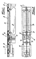
- eine erfindungsgemäße Bahnvorrichtung in schematischer Seitenansicht,
- Fig. 2
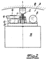
- einen Schnitt durch die Fig. 1,
- Fig. 3
- eine Aufsicht auf den Gegenstand nach Fig. 1,
- Fig. 4
- eine abgewandelte Ausführungsform in schematischer Aufsicht, und
- Fig. 5
- einen Schnitt durch Fig. 4.
- Fig. 1
- a web device according to the invention in a schematic side view,
- Fig. 2
- 2 shows a section through FIG. 1,
- Fig. 3
- 1 is a top view of the object according to FIG. 1,
- Fig. 4
- a modified embodiment in schematic supervision, and
- Fig. 5
- a section through Fig. 4th
In den Figuren ist eine Bahnvorrichtung, nach dem
Ausführungsbeispiel eine Hängebahnvorrichtung dargestellt,
die als Einschienenhängebahn im Rahmen der Fig. 1 bis 3
oder als Doppelschienenhängebahn bei der Ausführungsform
nach den Fig. 4 und 5 ausgebildet ist. Dabei greift die
jeweilige Schienenhängebahn auf I-förmige (vgl. Fig. 1 bis
3) oder U-förmige (vgl. Fig. 4 und 5) Profilschienen 1
zurück, die einen als Fahrstrecke 2 ausgeführten Schienenstrang
formen. Selbstverständlich können auch mehrere
Schienenstränge aus Profilschienen 1 nebeneinander eine
Mehrschienenanordnung für die Fahrstrecke 2 formen. Darüber
hinaus sind vorliegend ein oder zwei Wagen 3 in Gestalt von
Hängewagen 3 verwirklicht, welche jeweils einen Hängewagenzug
bilden. Dieser Hängewagenzug bzw. die Hängewagen 3
wird bzw. werden mit Hilfe einer Antriebsvorrichtung 4
entlang der Fahrstrecke 2 hin- und herbewegt.In the figures is a track device, according to the
Embodiment shown a monorail device,
which as a monorail overhead conveyor in the context of FIGS. 1 to 3
or as a double rail monorail in the
Bei der dargestellten Antriebsvorrichtung 4 handelt es sich
erfindungsgemäß um ein oder zwei Druckluftmotoren 6,
insbesondere Druckluftkolbenmotoren 6, die von einem mitgeführten
Druckluftspeicher 5 - nach dem Ausführungsbeispiel
zwei Druckluftflaschen 5 - mit Druckluft versorgt
werden. Der Detailaufbau des Druckluftmotors bzw. Druckluftkolbenmotors
6 mag so gewählt sein, wie dies in der
eingangs bereits beschriebenen WO 98/12 062 detailliert
dargestellt ist. Wie dort kann der im Rahmen des Ausführungsbeispiels
eingesetzte Druckluftkolbenmotor 6 alternativ
auch als Verbrennungsmotor arbeiten, wird also in
diesem Fall nicht mit Druckluft beschickt. Es handelt sich
folglich um einen Hybridmotor. Daneben sorgt eine geknickte
Kurbelwelle in den jeweiligen Kolben-/Zylindereinheiten für
lange Verweilzeiten am oberen Totpunkt, damit sich die
erwärmte Druckluft möglichst ungehindert ausdehnen kann und
die Rückwärtsbewegung des Kolbens in Verbindung mit der
zuströmenden Druckluft optimal bewerkstelligt.The
Anhand der Fig. 1 wird deutlich, dass der vordere Hängewagen
3 den Speicher bzw. Druckluftspeicher 5 und der
hintere Hängewagen 3 eine Transportlast 7 trägt. Selbstverständlich
kann der hintere Transportwagen 3 zusätzlich
einen weiteren Speicher 5 bzw. zugehörige Druckluftflaschen
5 aufnehmen, wie dies in der Fig. 3 angedeutet ist. Bei der
Transportlast handelt es sich nach dem Ausführungsbeispiel
um einen Wasserspeicher 7, insbesondere Wassertank 7, welcher
zur Versorgung einer nur angedeuteten Löschvorrichtung
10 dient (vgl. Fig. 4). Diese Löschvorrichtung 10 ist
frontseitig und gegebenenfalls rückseitig des aus den
beiden Hängewagen 3 zusammengesetzten Zuges angeordnet,
damit dieser in Vor- und Rückwärtsrichtung entsprechende
Löschaufgaben bewältigen kann.1 that the
Wie man anhand der Figuren unschwer erkennen kann, ist die
beschriebene Hängebahnvorrichtung in einem Tunnelausbau 8
angeordnet, wobei ein oder mehrere nicht ausdrücklich
gezeigte Temperatursensoren zur automatischen Auslösung des
jeweiligen Druckluftmotors 6 und/oder der Löschvorrichtung
10 in Tunnellängsrichtung angeordnet sind. Der Druckluftmotor
6 bzw. die Antriebsvorrichtung 4 weist zwei Reibräder
9 auf, die sich paarweise in bezug auf einen Steg der I-förmigen
Profilschiene 1 gegenüberliegen und für den Antrieb
des jeweiligen Hängewagens 3 dienen (vgl. Fig. 1 bis
3).As you can easily see from the figures, is the
Monorail device described in a
Im Rahmen des Ausführungsbeispiels nach den Fig. 4 und 5
sind zusätzlich oder alternativ zu den Reibrädern 9 Antriebsräder
11 und/oder Laufräder 12 vorgesehen. Außerdem
besitzen die Profilschienen 1 im Querschnitt eine U-Form
und sind gemäß Fig. 5 mit zugehörigen, die Räder 9, 11, 12
umgreifenden U-Flanschen 13 ausgerüstet. Die unteren U-Schenkel
13a dieser U-Flansche stellen die eigentliche
Fahrstrecke 2 für die Räder 11, 12 dar. Dagegen sorgt eine
U-Basis 13b für eine seitliche Führung des Hängewagens 3,
und zwar in Verbindung mit seitlichen Rädern 9', die nicht
notwendigerweise als Reibräder 9 ausgeführt sein müssen.
Schließlich bilden die weiteren U-Schenkel 13c einen senkrechten
Abschluss und erstrecken sich - wie die U-Schenkel
13a - im wesentlichen in Fahrtrichtung bzw. Längsrichtung
der Fahrstrecke 2 (Horizontalrichtung).In the context of the exemplary embodiment according to FIGS. 4 and 5
are 9 drive wheels in addition or as an alternative to the friction wheels
11 and / or
Damit die Räder 9, 11 und 12 die erforderlichen Beschleunigungskräfte
auf die Fahrstrecke 2 übertragen können, sind
sie mit lediglich angedeuteten Kunststoffringen 14 laufflächenseitig
ummantelt, die auf zugehörige Radnaben aufvulkanisiert
werden. Eine im Haltebereich der Hängewagen 3
vorgesehene Räderentlastungseinrichtung sorgt dafür, dass
die Kunststoffringe bzw. Laufringe 14 während der Standzeit
der Hängewagen 3 keine unerwünschten "Platten" erhalten,
also von der Fahrstrecke 2 beabstandet werden.So that the
Bei dem Druckluftmotor bzw. Druckluftkolbenmotor 6 handelt
es sich um einen modifizierten (Mehr-)Kolbenmotor, während
die Druckluftflaschen 5 als Normflaschen ausgeführt sind
und in seitlich angeordneten Aufnahmen 15 aufgenommen
werden. Diese Aufnahmen 15 finden sich im Bereich von über
die Fahrstrecke 2 quer bzw. seitlich überstehenden Auslegern
16.The compressed air motor or compressed
Demgegenüber wird die Transportlast 7 bzw. der Wassertank 7
in der Regel schwerpunktnah auf dem Hängewagen 3 platziert,
wir dies die Fig. 1 und 4 unmittelbar deutlich machen.In contrast, the
Um den innerhalb des dargestellten Tunnels bzw. Tunnelausbaus
8 deckenseitig zur Verfügung stehenden Bauraum
optimal zu nutzen, weist die Fahrstrecke 2 mit Hängewagen 3
inklusive Auslegern 16 und montierten Druckluftflaschen 5
sowie Wassertank 7 eine an ein Kreissegment angelehnte
wirksame Fläche auf, die sich aus der Fig. 5 unmittelbar
ergibt.To the inside of the shown tunnel or
Mehrere Hängewagen 3 können modular zu einem Hängewagenzug
zusammengestellt und an den jeweiligen Einsatzzweck angepasst
werden. So ist es denkbar, einen Hängewagen 3 beispielsweise
mit der Antriebseinrichtung 4 und den Druckluftflachen
5 auszurüsten, während ein anderer Hängewagen 3
den Wassertank 7 trägt. Dabei kann der zweite Hängewagen 3
auf seinen Auslegern 16 zusätzlich mit weiteren Transportlasten
7 bzw. Druckluftflaschen 5 ausgerüstet werden. Dies
hängt von dem primären Verwendungszweck ab.Several hanging
Schließlich sorgen nicht gezeigte Wegsensoren entlang der
Fahrstrecke 2 für eine Rückmeldung des momentanen Aufenthaltsortes
des Hängewagens 3 an eine Leitstelle.Finally, path sensors (not shown) along the
Claims (10)
- A track apparatus, particularly a suspended track apparatus, comprising a travelling section (2), and comprising at least one carriage (3), particularly a suspended carriage (3), which can move to and fro along the travelling section (2) with the aid of at least one driving apparatus (4) constructed as a compressed air motor (6), whereinthe at least one carriage (3) bears a water storage device (7) as a transported load (7) for supplying an extinguishing apparatus (10) which produces a water discharge, and whereinthe energy necessary for the discharge of water from the extinguishing apparatus (10) is provided by the compressed air.
- A track apparatus according to claim 1, characterised in that two or more carriages (3) are provided, wherein one carriage (3) bears a storage device (5) for the supply of compressed air and the other carriage (3) bears the transported load (7).
- A track apparatus according to claim 1 or 2, characterised in that the transported load (7) is a water tank (7) for supplying the extinguishing apparatus (10).
- A track apparatus according to claim 3, characterised in that the extinguishing apparatus (10) is constructed as a water emission and atomising installation.
- A track apparatus according to any one of claims 1 to 4, characterised in that it is disposed in a tunnel lining (8), and that one or more temperature sensors for the automatic operation of the driving apparatus (4) and/or of the extinguishing apparatus (10) are provided in the longitudinal direction of the tunnel.
- A track apparatus according to any one of claims 1 to 5, characterised in that the driving apparatus (4) comprises two or more friction wheels (9) for driving the carriage (3), which friction wheels are disposed in pairs and opposite each other with respect to a web of an I-shaped sectional rail (1).
- A track apparatus according to any one of claims 1 to 5, characterised in that the driving apparatus (4) comprises two or more driving wheels (11) and/or running wheels (12) which rest on the travelling section (2).
- A track apparatus according to any one of claims 1 to 7, characterised in that the travelling section (2) comprises U-shaped flanges (13) which fit round the friction wheels (9), the driving wheels (11) and/or the running wheels (12).
- A track apparatus according to any one of claims 1 to 8, characterised in that the respective carriage (3) comprises extension arms (16) which protrude laterally beyond the travelling section (2), for receiving the storage device (5) and/or the transported load (7).
- A track apparatus according to any one of claims 1 to 9, characterised in that a plurality of carriages (3) forms a carriage train which is adapted to the respective purpose of use.
Applications Claiming Priority (2)
| Application Number | Priority Date | Filing Date | Title |
|---|---|---|---|
| DE19944326 | 1999-09-15 | ||
| DE19944326 | 1999-09-15 |
Publications (3)
| Publication Number | Publication Date |
|---|---|
| EP1085128A2 EP1085128A2 (en) | 2001-03-21 |
| EP1085128A3 EP1085128A3 (en) | 2001-11-07 |
| EP1085128B1 true EP1085128B1 (en) | 2004-03-03 |
Family
ID=7922184
Family Applications (1)
| Application Number | Title | Priority Date | Filing Date |
|---|---|---|---|
| EP00118566A Expired - Lifetime EP1085128B1 (en) | 1999-09-15 | 2000-08-26 | Track device, especially suspended track, for example monorail and/or double railed suspended track |
Country Status (3)
| Country | Link |
|---|---|
| EP (1) | EP1085128B1 (en) |
| AT (1) | ATE261023T1 (en) |
| DE (1) | DE50005495D1 (en) |
Cited By (1)
| Publication number | Priority date | Publication date | Assignee | Title |
|---|---|---|---|---|
| DE102017121603A1 (en) * | 2017-09-18 | 2019-03-21 | Smt Scharf Ag | Conveying and transport system for tunnel structures |
Families Citing this family (2)
| Publication number | Priority date | Publication date | Assignee | Title |
|---|---|---|---|---|
| CN103010233B (en) * | 2011-09-23 | 2016-08-03 | 徐广杰 | Empty rail mine car |
| CN107034746B (en) * | 2017-04-21 | 2023-05-16 | 中国五冶集团有限公司 | Assembled connecting structure for suspended type monorail traffic track beam and construction method |
Family Cites Families (6)
| Publication number | Priority date | Publication date | Assignee | Title |
|---|---|---|---|---|
| US1628217A (en) * | 1923-08-10 | 1927-05-10 | Baum Ernst Otto | Compressed-air locomotive |
| DE2750916C2 (en) * | 1977-11-14 | 1981-10-01 | Maschinenfabrik Scharf Gmbh, 4700 Hamm | Compressed air-powered transport system for underground mining operations |
| DE3326103A1 (en) | 1983-07-20 | 1985-03-14 | Muckenhaupt GmbH, 4320 Hattingen | Articulated butt joint for suspended rails of monorail overhead conveyors |
| DE4210175A1 (en) * | 1992-03-26 | 1993-09-30 | Mannesmann Ag | Storage system with distributor vehicles driven by pneumatic motors - which are supplied with compressed air from pressure vessel mounted on vehicle. |
| JPH1088996A (en) * | 1996-09-12 | 1998-04-07 | Shinko Electric Co Ltd | Fire robot for inside of tunnel |
| FR2753487B1 (en) | 1996-09-19 | 1998-11-20 | Guy Negre | INSTALLATION OF HIGH-PRESSURE COMPRESSED AIR SUPPLY COMPRESSORS FOR DE-EMISSION OR DEPOLLUTING ENGINE |
-
2000
- 2000-08-26 AT AT00118566T patent/ATE261023T1/en not_active IP Right Cessation
- 2000-08-26 DE DE50005495T patent/DE50005495D1/en not_active Expired - Lifetime
- 2000-08-26 EP EP00118566A patent/EP1085128B1/en not_active Expired - Lifetime
Cited By (2)
| Publication number | Priority date | Publication date | Assignee | Title |
|---|---|---|---|---|
| DE102017121603A1 (en) * | 2017-09-18 | 2019-03-21 | Smt Scharf Ag | Conveying and transport system for tunnel structures |
| WO2019052594A1 (en) | 2017-09-18 | 2019-03-21 | Smt Scharf Ag | Conveying and transport system for tunnel constructions |
Also Published As
| Publication number | Publication date |
|---|---|
| DE50005495D1 (en) | 2004-04-08 |
| EP1085128A2 (en) | 2001-03-21 |
| ATE261023T1 (en) | 2004-03-15 |
| EP1085128A3 (en) | 2001-11-07 |
Similar Documents
| Publication | Publication Date | Title |
|---|---|---|
| DE2411241C3 (en) | Railway system | |
| DE1455034A1 (en) | Train drive for rail car trains to carry out the process | |
| DE2646828A1 (en) | CONTINUOUS TRANSPORT SYSTEM | |
| DE102020005156A1 (en) | Combined road/rail wheel device for road and rail operations | |
| EP1085128B1 (en) | Track device, especially suspended track, for example monorail and/or double railed suspended track | |
| DE2216284C2 (en) | Railway system with driverless vehicles pulled by a pull rope | |
| DE19638578A1 (en) | Elevated railway system | |
| DE202009015830U1 (en) | Modular movable measuring portal | |
| DE2839496C2 (en) | Method and device for transferring material to be conveyed from a rail-mounted driven roller conveyor to a drivable roller conveyor with frictional engagement designed as a storage area | |
| DE1930991A1 (en) | Self-supporting track for hanging railways | |
| DE2015306A1 (en) | Conveyance facility | |
| DE2140901A1 (en) | SHOULDER AUXILIARY DEVICE FOR HANDLING AND SHIFTING POINTS IN UNDERGROUND MINING, IN PARTICULAR FOR MONORAR RAILWAYS | |
| DE19723768C2 (en) | Means of transport for people and materials in underground mining and tunneling | |
| DE2615940A1 (en) | TRANSPORT VEHICLE, IN PARTICULAR FOR PERSONNEL TRANSPORTATION IN URBAN TRANSPORT NETWORKS | |
| DE3914093A1 (en) | Magnetic suspension system for track guided vehicles - employs magnetic field to maintain clearance space on both sides of guide rails with retractable rollers | |
| DE611091C (en) | Compressed air cylinder car pushing device mounted between the railroad tracks | |
| DE202015104196U1 (en) | Holding and changing station for cabin vehicles of a rail-bound passenger transport system | |
| DE19925507B4 (en) | Device for transporting heavy loads on site in underground mining and tunneling | |
| DE102018200043B4 (en) | Locking device for locking the railroad cars | |
| DE2750916A1 (en) | Compressed air conveyor unit - has air extractor wheel, drive wagon and guide rail integrated into rectangular profile | |
| DE1755922C3 (en) | Underground high-speed train in a tube | |
| DE3838771A1 (en) | Drive for a positively guided special conveyor means for use underground | |
| DE2641237A1 (en) | Mine monorail train brake trolley - has powered swivelling clamping shoes mounted in pairs and engaging rail at acute angle | |
| EP0853143A1 (en) | Device for moving beams used in the transportation of objects | |
| DE2707889A1 (en) | Traffic system with magnetically levitated vehicles - has overhead weather protection for passengers, and emergency running contact faces |
Legal Events
| Date | Code | Title | Description |
|---|---|---|---|
| PUAI | Public reference made under article 153(3) epc to a published international application that has entered the european phase |
Free format text: ORIGINAL CODE: 0009012 |
|
| AK | Designated contracting states |
Kind code of ref document: A2 Designated state(s): AT BE CH CY DE DK ES FI FR GB GR IE IT LI LU MC NL PT SE |
|
| AX | Request for extension of the european patent |
Free format text: AL;LT;LV;MK;RO;SI |
|
| PUAL | Search report despatched |
Free format text: ORIGINAL CODE: 0009013 |
|
| AK | Designated contracting states |
Kind code of ref document: A3 Designated state(s): AT BE CH CY DE DK ES FI FR GB GR IE IT LI LU MC NL PT SE |
|
| AX | Request for extension of the european patent |
Free format text: AL;LT;LV;MK;RO;SI |
|
| RIC1 | Information provided on ipc code assigned before grant |
Free format text: 7E 01B 25/22 A, 7B 61C 7/02 B, 7E 21F 5/00 B |
|
| 17P | Request for examination filed |
Effective date: 20020322 |
|
| AKX | Designation fees paid |
Free format text: AT BE CH CY DE DK ES FI FR GB GR IE IT LI LU MC NL PT SE |
|
| 17Q | First examination report despatched |
Effective date: 20030228 |
|
| GRAP | Despatch of communication of intention to grant a patent |
Free format text: ORIGINAL CODE: EPIDOSNIGR1 |
|
| GRAS | Grant fee paid |
Free format text: ORIGINAL CODE: EPIDOSNIGR3 |
|
| GRAA | (expected) grant |
Free format text: ORIGINAL CODE: 0009210 |
|
| AK | Designated contracting states |
Kind code of ref document: B1 Designated state(s): AT BE CH CY DE DK ES FI FR GB GR IE IT LI LU MC NL PT SE |
|
| PG25 | Lapsed in a contracting state [announced via postgrant information from national office to epo] |
Ref country code: GB Free format text: LAPSE BECAUSE OF FAILURE TO SUBMIT A TRANSLATION OF THE DESCRIPTION OR TO PAY THE FEE WITHIN THE PRESCRIBED TIME-LIMIT Effective date: 20040303 Ref country code: CY Free format text: LAPSE BECAUSE OF FAILURE TO SUBMIT A TRANSLATION OF THE DESCRIPTION OR TO PAY THE FEE WITHIN THE PRESCRIBED TIME-LIMIT Effective date: 20040303 Ref country code: IE Free format text: LAPSE BECAUSE OF FAILURE TO SUBMIT A TRANSLATION OF THE DESCRIPTION OR TO PAY THE FEE WITHIN THE PRESCRIBED TIME-LIMIT Effective date: 20040303 Ref country code: FI Free format text: LAPSE BECAUSE OF FAILURE TO SUBMIT A TRANSLATION OF THE DESCRIPTION OR TO PAY THE FEE WITHIN THE PRESCRIBED TIME-LIMIT Effective date: 20040303 Ref country code: NL Free format text: LAPSE BECAUSE OF FAILURE TO SUBMIT A TRANSLATION OF THE DESCRIPTION OR TO PAY THE FEE WITHIN THE PRESCRIBED TIME-LIMIT Effective date: 20040303 |
|
| REG | Reference to a national code |
Ref country code: GB Ref legal event code: FG4D Free format text: NOT ENGLISH |
|
| REG | Reference to a national code |
Ref country code: CH Ref legal event code: EP |
|
| REG | Reference to a national code |
Ref country code: IE Ref legal event code: FG4D Free format text: GERMAN |
|
| REF | Corresponds to: |
Ref document number: 50005495 Country of ref document: DE Date of ref document: 20040408 Kind code of ref document: P |
|
| PG25 | Lapsed in a contracting state [announced via postgrant information from national office to epo] |
Ref country code: SE Free format text: LAPSE BECAUSE OF FAILURE TO SUBMIT A TRANSLATION OF THE DESCRIPTION OR TO PAY THE FEE WITHIN THE PRESCRIBED TIME-LIMIT Effective date: 20040603 Ref country code: DK Free format text: LAPSE BECAUSE OF FAILURE TO SUBMIT A TRANSLATION OF THE DESCRIPTION OR TO PAY THE FEE WITHIN THE PRESCRIBED TIME-LIMIT Effective date: 20040603 Ref country code: GR Free format text: LAPSE BECAUSE OF FAILURE TO SUBMIT A TRANSLATION OF THE DESCRIPTION OR TO PAY THE FEE WITHIN THE PRESCRIBED TIME-LIMIT Effective date: 20040603 |
|
| PG25 | Lapsed in a contracting state [announced via postgrant information from national office to epo] |
Ref country code: ES Free format text: LAPSE BECAUSE OF FAILURE TO SUBMIT A TRANSLATION OF THE DESCRIPTION OR TO PAY THE FEE WITHIN THE PRESCRIBED TIME-LIMIT Effective date: 20040614 |
|
| REG | Reference to a national code |
Ref country code: CH Ref legal event code: NV Representative=s name: KELLER & PARTNER PATENTANWAELTE AG |
|
| NLV1 | Nl: lapsed or annulled due to failure to fulfill the requirements of art. 29p and 29m of the patents act | ||
| PG25 | Lapsed in a contracting state [announced via postgrant information from national office to epo] |
Ref country code: LU Free format text: LAPSE BECAUSE OF NON-PAYMENT OF DUE FEES Effective date: 20040826 |
|
| PG25 | Lapsed in a contracting state [announced via postgrant information from national office to epo] |
Ref country code: BE Free format text: LAPSE BECAUSE OF NON-PAYMENT OF DUE FEES Effective date: 20040831 Ref country code: MC Free format text: LAPSE BECAUSE OF NON-PAYMENT OF DUE FEES Effective date: 20040831 |
|
| GBV | Gb: ep patent (uk) treated as always having been void in accordance with gb section 77(7)/1977 [no translation filed] |
Effective date: 20040303 |
|
| REG | Reference to a national code |
Ref country code: IE Ref legal event code: FD4D |
|
| ET | Fr: translation filed | ||
| PLBE | No opposition filed within time limit |
Free format text: ORIGINAL CODE: 0009261 |
|
| STAA | Information on the status of an ep patent application or granted ep patent |
Free format text: STATUS: NO OPPOSITION FILED WITHIN TIME LIMIT |
|
| 26N | No opposition filed |
Effective date: 20041206 |
|
| BERE | Be: lapsed |
Owner name: *NEUHAUSER G.M.B.H. Effective date: 20040831 |
|
| BERE | Be: lapsed |
Owner name: *NEUHAUSER G.M.B.H. Effective date: 20040831 |
|
| PG25 | Lapsed in a contracting state [announced via postgrant information from national office to epo] |
Ref country code: PT Free format text: LAPSE BECAUSE OF NON-PAYMENT OF DUE FEES Effective date: 20040803 |
|
| PGFP | Annual fee paid to national office [announced via postgrant information from national office to epo] |
Ref country code: CH Payment date: 20080915 Year of fee payment: 9 |
|
| PGFP | Annual fee paid to national office [announced via postgrant information from national office to epo] |
Ref country code: AT Payment date: 20080828 Year of fee payment: 9 Ref country code: IT Payment date: 20080829 Year of fee payment: 9 |
|
| REG | Reference to a national code |
Ref country code: CH Ref legal event code: PL |
|
| PG25 | Lapsed in a contracting state [announced via postgrant information from national office to epo] |
Ref country code: CH Free format text: LAPSE BECAUSE OF NON-PAYMENT OF DUE FEES Effective date: 20090831 Ref country code: LI Free format text: LAPSE BECAUSE OF NON-PAYMENT OF DUE FEES Effective date: 20090831 |
|
| PG25 | Lapsed in a contracting state [announced via postgrant information from national office to epo] |
Ref country code: AT Free format text: LAPSE BECAUSE OF NON-PAYMENT OF DUE FEES Effective date: 20090826 |
|
| PG25 | Lapsed in a contracting state [announced via postgrant information from national office to epo] |
Ref country code: IT Free format text: LAPSE BECAUSE OF NON-PAYMENT OF DUE FEES Effective date: 20090826 |
|
| REG | Reference to a national code |
Ref country code: FR Ref legal event code: ST Effective date: 20110502 |
|
| PG25 | Lapsed in a contracting state [announced via postgrant information from national office to epo] |
Ref country code: FR Free format text: LAPSE BECAUSE OF NON-PAYMENT OF DUE FEES Effective date: 20100831 |
|
| PGFP | Annual fee paid to national office [announced via postgrant information from national office to epo] |
Ref country code: FR Payment date: 20090914 Year of fee payment: 10 |
|
| PGFP | Annual fee paid to national office [announced via postgrant information from national office to epo] |
Ref country code: DE Payment date: 20140919 Year of fee payment: 15 |
|
| REG | Reference to a national code |
Ref country code: DE Ref legal event code: R119 Ref document number: 50005495 Country of ref document: DE |
|
| PG25 | Lapsed in a contracting state [announced via postgrant information from national office to epo] |
Ref country code: DE Free format text: LAPSE BECAUSE OF NON-PAYMENT OF DUE FEES Effective date: 20160301 |