EP1085111A1 - Procédé de régénération des bains d'électrodéposition métallique - Google Patents
Procédé de régénération des bains d'électrodéposition métallique Download PDFInfo
- Publication number
- EP1085111A1 EP1085111A1 EP99117902A EP99117902A EP1085111A1 EP 1085111 A1 EP1085111 A1 EP 1085111A1 EP 99117902 A EP99117902 A EP 99117902A EP 99117902 A EP99117902 A EP 99117902A EP 1085111 A1 EP1085111 A1 EP 1085111A1
- Authority
- EP
- European Patent Office
- Prior art keywords
- cathode
- cell
- enrichment
- metal
- gas
- Prior art date
- Legal status (The legal status is an assumption and is not a legal conclusion. Google has not performed a legal analysis and makes no representation as to the accuracy of the status listed.)
- Withdrawn
Links
Images


Classifications
-
- C—CHEMISTRY; METALLURGY
- C25—ELECTROLYTIC OR ELECTROPHORETIC PROCESSES; APPARATUS THEREFOR
- C25D—PROCESSES FOR THE ELECTROLYTIC OR ELECTROPHORETIC PRODUCTION OF COATINGS; ELECTROFORMING; APPARATUS THEREFOR
- C25D21/00—Processes for servicing or operating cells for electrolytic coating
- C25D21/12—Process control or regulation
- C25D21/14—Controlled addition of electrolyte components
Definitions
- the present invention deals with a replenishment process for metal electrodeposition baths, i.e. with a step of metal plating processes in which the electrolyte is enriched in metal cations to maintain substantially constant the metal cations concentration of the electrodeposition baths. More particularly, the invention relates to the replenishment step in plating processes from Copper-containing alkaline pyrophosphate or acid sulphate baths and from Zinc-containing acid sulphate baths, using insoluble anodes.
- the concentration of Cu 2+ and Zn 2+ is kept constant by recirculating the working solution in an enrichment cell, or replenishment cell.
- the mechanism which ensures such adhesion is generally the chemical bonding obtained through the formation of sulphide bonds between a metal, which easily undergoes sulfidation, and the rubber; this reaction occurs mainly during the vulcanisation process. Alloys of interest for such applications are brass, Zn-Co and Zn-Mn.
- Such alloys also enhance the corrosion resistance of the steelcord.
- Such coatings are generally applied to steel wires whose diameter is larger than that of the final steelcord, such wires are therefore drawn after electroplating, the coating thus performs also a lubricating action during the drawing process.
- the standard brass-coating process of steel wire typically consists in the following unit operations.
- Step # 5 could be omitted by having a thickness of Cu layer in step # 4 of about 1 arm.
- the concentration of the Cu 2+ e Zn 2+ cations is generally kept constant by the oxidation of soluble Cu and Zn anodes, respectively.
- EP-A-0508212 in the name of The Goodyear Tyre and Rubber Co., discloses a process of keeping the Cu concentration constant with a system comprising insoluble anodes and an cation-exchange membrane-based replenishment device. According to this process, there is provided a replenishment, or enrichment, cell wherein a Cu anode is dissolved and the selective membrane avoids the Cu ions to migrate to the cathode, be reduced and redeposit at the cathode.
- the selective membrane acts as a chemical and selective separation means for Cu ions present in the enrichment bath.
- the present invention deals with a peculiar procedure for the supply of metal cations, and especially of Cu 2+ and Zn 2+ , for keeping the concentration of these cations constant in applications of alkaline pyrophosphate Cu and of acid sulphate Cu or Zn electroplating processes carried out with insoluble anodes.
- insoluble anodes shows marked advantages in comparison with the traditional soluble-anode process:
- Cu 2+ and Zn 2+ supply to the working (i.e. deposition) cell is achieved by circulating a given amount of the working electrolyte from the working cell to the enrichment cell where dissolution of suitable anodes takes place: metal deposition at the cathode of the enrichment cell is reduced or substantially avoided, in the absence of the above disclosed selective membrane or of other cation chemical separation means located between anode and cathode of said enrichment cell, by carrying out cathodic reduction reactions that produce or consume a gas.
- Said reduction reaction can be divided into two main groups.
- the electrolyte in the enrichment cell is in contact with a large-area Cu or Zn anode and a small-area cathode (e.g., but with no limitation, a metal wire of suitable mechanical properties).
- a large-area Cu or Zn anode and a small-area cathode e.g., but with no limitation, a metal wire of suitable mechanical properties.
- the anode tends to dissolve with an anodic efficiency close to 100% (the only technically relevant anodic reaction being the oxidation of Cu to Cu 2+ and of Zn to Zn 2+ ), at the cathode the reduction of Cu 2+ or Zn 2+ to metallic Cu or Zn occurs under limiting-current conditions (the cathodic kinetics is controlled by mass-transport to the cathode) together with a side reaction: the reduction of H + to H 2 (cathodic current efficiency less that 100%).
- the difference between the cathodic and anodic current efficiencies is the enrichment factor for the solution.
- the enrichment factor can be optimized by acting on the cell geometry, the hydrodynamic conditions of the electrolyte and the current density imposed to the electrodic system.
- the limiting-current electrodeposition brings about the formation of an incoherent and powdery cathodic deposit, suitable means of powder removal will therefore be used. Notwithstanding the possibility of engineering optimisation, any feasible implementation of the process leads to an effective enrichment in Cu 2+ of the solution.
- the electrolyte in the enrichment cell is brought into contact with a Cu or Zn anode and a suitable cathode.
- the cathode is a porous electrode with a catalytic performance for the reaction of oxygen gas reduction to hydroxide anion in alkaline aqueous environment, such as an oxygen fuel-cell electrode; the alkaline environment is favourable in that most commercially available porous gas electrodes can be adopted.
- oxygen-rich gas either pure oxygen or compressed air of the suitable pressure to achieve the required oxygen activity
- solid material which acts both as current-carrier and electrocatalyst for oxygen reduction.
- reaction can be carried out in a packed bed cathode system made of catalytic spheroids (e.g. silver or graphite activated with platinum nuclei) through which the oxygen-rich gas flows in contact with the ion solution to be enriched.
- catalytic spheroids e.g. silver or graphite activated with platinum nuclei
- the reduction of metal - which would be a loss term as far as cation-enrichment of the working solution is concerned and could damage the gas electrode - can occur only if O 2 reduction takes place under limiting current density conditions.
- the enrichment factor can be optimized by acting on the type of the cell (porous-electrode cell or packed sphere bed electrode) on the cell geometry, on the hydrodynamic conditions of the electrolyte and on the current density imposed to the cell. Even though engineering optimisations are possible, any feasible implementation of the process produces an efficient Cu 2+ or Zn 2+ enrichment of the solution.
- steel wire 1 is coated with a layer of a few ⁇ m (typically 0,5 ⁇ 5 ⁇ m and preferably 1 ⁇ 2 ⁇ m) in a deposition, or working, cell 2.
- Wire 1 is polarised cathodically by generator 3, generally operated in galvanostatic (current control) conditions (a successful application of potentiostatic, i.e. voltage control, conditions is possible too), via contact pulleys 4, known in the art.
- Steel wire 1 is contacting an aqueous solution of Cu 2+ -pyrophosphate, or Cu 2+ acid sulphate or Zn 2+ acid sulphate 5 while flowing through the cell. Solution 5 is also in contact with an insoluble anode 6 and electrically connected to generator 3.
- the working solution displays a cation concentration typically in the range 0.10 ⁇ 0.25 ozs./gall. for Cu 2+ in pyrophosphate baths, 9 ⁇ 12 ozs/gall for Cu 2+ in acid sulphate baths, and 10 ⁇ 13 ozs/gall for Zn 2+ in acid sulphate baths.
- Pyrophosphate anion concentration is typically in the range 0.80 ⁇ 1.5 ozs./gall
- sulfuric acid concentration in Cu and Zn cation solutions is typically in the range 8.0 ⁇ 10.0 ozs/gall and the quantity necessary to reach a pH of about 3, respectively.
- the solution pH is generally controlled in the following intervals: Cu 2+ pyrophosphate baths 7.5 ⁇ 9.5 and preferably close to 8.5, Zn 2+ - sulphate baths 2.75 ⁇ 3.25 and preferably close to 3.0.
- the temperature of working solution 5 is regulated in the range 100 ⁇ 150°F and preferably close to 120°F.
- Generator 3 is controlled in such a way that it gives cathodic current densities in the interval 0.25 ⁇ 1.5 A/sq.in..
- the steel wire crosses the electrodeposition cell at a velocity suitable in order to guarantee - for a given cathodic current density - an optimal residence time of the wire in the cation solution according to the desired coating thickness.
- the Cu 2+ or Zn 2+ concentration of working solution 5 diminishes (in an approximately linear way as a function of time) and it is necessary to replenish the solution with metal cations in order to keep the optimal concentration constant against time.
- the enrichment device is connected in series to the recirculation system (recirculation pumps 8, recirculation tubing 9, working electrolyte storage tank 10, the latter can be equipped with pH and Cu 2+ /Zn 2+ concentration controls), which is generally available in electrodeposition systems of this kind, allowing the treatment of a flow Q of electrolyte.
- the recirculation system recirculation pumps 8, recirculation tubing 9, working electrolyte storage tank 10, the latter can be equipped with pH and Cu 2+ /Zn 2+ concentration controls
- a portion Q 1 (Q>Q 1 ) is derived from the recirculation flow Q and is delivered to the enrichment device 7, comprising an enrichment cell 11 and possibly a storage and diluting tank for the treated electrolyte 12, a dilution system 13 supplying demineralised water to tank 12 and the relevant pumping systems 14 and pipelines 15.
- the treated flow Q 1 is added to the working electrolyte storage tank 10, from which the flow Q is pumped to the wire-coating cell.
- enrichment cell 11 can be implemented according to one of two embodiments of the process: i. (see Figure 2) anodic Cu or Zn dissolution with simultaneous limiting-current electrodeposition of Cu or Zn (cathodic efficiency less than 100%); ii. (see Figure 3) anodic dissolution of Cu or Zn with oxygen cathode.
- the Cu 2+ or Zn 2+ -enriched solution is contacted with at least one Cu or Zn anode la whose surface area is much larger than the surface of cathode 3a. It is generally advisable to use Cu or Zn spheroids (nuggets) or scraps with typical dimension of a few inches which can be conveniently contained in one or two suitable commercial anode basket (e.g. made of Ti, see above cited EP application for details); if two anode baskets are present, the wire cathode is usually located between them.
- the anodic polarisation is obtained by connecting the Cu or Zn anode to the positive terminal of the generator 2a (of the same characteristics as the generator 3 of Figure 1).
- the anodic metal is oxidised to the relevant cation; as far as the material balance is concerned, it is a very good approximation to consider this as the only anodic reaction (100% anodic current efficiency) taking place in the enrichment cell.
- the anodic Cu or Zn is dissolved during the operation of the enrichment cell and it is therefore necessary to add Cu spheroids or scarps - typically batchwise - to the anode basket(s).
- the thus enriched anolyte is in contact with a metal cathods 3a (e.g. a steel wire) whose surface area is much smaller than the anodic one.
- the cathodic polarisation is achieved by connecting the cathodic wire to the negative terminal of generator 2a (of the same characteristics as the generator 3 of Figure 1).
- the thermodynamically favoured cathodic reaction in the system at hand is Cu 2+ or Zn 2+ reduction to Cu metal or Zn metal. The rate of such reaction is limited by mass transport of the cations to the cathode.
- the imposed current density is larger than these values and the exceeding current density is used up for the next competitive side reaction of hydrogen evolution from water. It is worth noting that the loss term for electrodeposition of Cu or Zn can be limited to very low values.
- a large area anode and a reduced area cathode can be used, as disclosed in figures 2 and 4.
- Container 16 is made of porous ceramic, fabric or similar material suitable to let the electrolyte flow through its pores and reach the cathode: this will avoid the commotion due to pumping in and out the enrichment cell to reach the cathode area, while enabling the process to proceed.
- a further advantage is obtained through the use of container 16: the flow from the cell to within container 16 being reduced, a lesser amount of CU cations reach the cathode, thus enhancing the limiting current conditions.
- container 16 is not a cation exchange membrane as disclosed in prior art.
- the membrane does not allow for Cu ions to flow through it: in present case porous container acts as a resistance to the flow of Cu ions, that is reduced but not impeded.
- the porous container can be dispensed with and a porous diaphragm, having analogous characteristics and defining a cathode area with respect to the anode(s) area(s), can be used.
- the overall effect of porous diaphragm or container is to reduce the effective diffusion coefficiency.
- a further way of enhancing limiting current conditions is by controlling the electrolyte temperature; temperature should be lowered to the lowest acceptable value that does not jeopardize the cell efficiency.
- the cathodic hydrogen-evolution reaction brings about a beneficial alkalinising; as a matter of fact, the working electrolyte tends to acidify in the wire-coating cell because of the anodic reaction at the insoluble anodes bringing about the consumption of hydroxide anions supporting the anodic oxygen gas evolution; in the case of analyses performed under this research, it was observed that the alkalinisation in the enrichment cell can compensate for the electrolyte acidification in the wire-coating cell perfectly; it is anyway advisable to provide the system with an automatic pH-control device.
- the limiting-current electrodeposition of Cu or Zn - necessary for the operation of the cathode of the limiting-current enrichment cell - can easily lead to the formation of dendritic or powdery deposits, it is therefore advisable to periodically clean the cathode.
- Such cleaning operation can be easily performed manually by simply wiping the cathode with a cloth.
- the cleaning operation can be very easily performed without interrupting the cell operation, e.g. with a device of the kind illustrated in Figure 4.
- FIG. 2 a top view of the limiting-current enrichment cell, shown in Figure 2, is given, one can note the large-surface-area anode 1a, the cathodic wire 3a and generator 2a.
- the cathodic wire forms a loop which is tensioned by two pulleys 19a and 19b and is connected to the cell through two seals 17 and 18 consisting of a disposable rigid plastic insert on the solution-side of the cell.
- the pulleys can be rotated periodically, e.g. by use of crank 20.
- the movement of the wire through the plastic inserts can detach the loose deposit which falls in a suitable container, e.g. above mentioned porous container 16, or can be removed from the bottom of the cells as a mud.
- the enriched Cu 2+ -pyrophosphate, Cu 2+ -sulphate or Zn 2+ -sulphate solutions are in contact with at least one Cu or Zn anode 1b with the same properties mentioned with reference to the limiting-current enrichment cell, except the requirement of a high surface area.
- the anodic polarisation is obtained by connecting the Cu or Zn anode to the positive terminal of generator 2b (of the same characteristics as the generator 3 of Figure 1). Cu metal and Zn metal oxidise to Cu 2+ and Zn 2+ , respectively; it is a sound technical approximation to judge this reaction as the only relevant one at the anode of the enrichment cell.
- the anolyte enriched in Cu 2+ or Zn 2+ is in contact with a bed of packed spheres or to some other sort of gas electrode 3b fed with a gas containing O 2 of suitable activity.
- the cathodic polarisation is achieved by connecting the gas electrode to the negative terminal of generator 2b (of the same characteristics as the generator 3 of Figure 1).
- the thermodynamically favoured cathodic reaction in the system of interest is the reduction of O 2 to OH - .
- the rate of such reaction is limited by the mass transport of O 2 to the electroactive regions of the cathode.
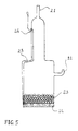
- Figure 5 shows a gas-cathode suitable for the invention process.
- the cathode is made of Pyrex glass and is equipped with gas inlet 21 and outlet 22.
- the electrically active region of the electrode consists of a packed sphere bed of Ag beads 23 of average diameter 200 ⁇ m, placed on a bored plate 24 of Ag, fixed to the Pyrex cylinder.
- the cathodic reaction of oxygen reduction of hydroxide anions brings about a beneficial alkalinising; as a matter of fact, the working electrolyte tends to acidify in the wire-coating cell because of the anodic reaction at the insoluble anodes bringing about the consumption of hydroxide anions supporting the anodic oxygen gas evolution; in the case of analyses performed under this research, it was observed that the alkalinisation in the enrichment cell can compensate for the electrolyte acidification in the wire-coating cell perfectly; it is anyway advisable to provide the system with an automatic pH-control device.
- the anode consists in two Ti anode baskets of dimensions 1 ⁇ 6 ⁇ 12 cu.in. hanging from opposite walls of the cell.
- the anode baskets contains Cu spheroids of diameter 0.5 in..
- the cathode is a fixed steel wire of of diameter 0.02 in., placed 8 in. above the bottom of the cell and centrally with respect to the two anodes, about 1.5 in. from each one of them.
- the cell is powered with a laboratory generator, the experiments were carried out under current control.
- the analysis of Cu concentration was performed by atomic absorption on discontinuously sampled portions of the electrolyte.
- Example 6 the enrichment of a Cu 2+ -pyrophosphate solution is described, with the oxygen-cathode process, object of the present invention.
- the cell was the same as described in Example 1.
- the anode was only one of the anode baskets used in Example 1.
- the gas cathode used in this Example is shown in Figure 6. This cathode was placed vertically in a central position in the enrichment cell.
- the cell is electrically connected as in Example 1, the experiment was carried out under current control.
- the analysis of Cu concentration and of pH were performed as in Example 1.
Landscapes
- Engineering & Computer Science (AREA)
- Chemical & Material Sciences (AREA)
- Automation & Control Theory (AREA)
- Chemical Kinetics & Catalysis (AREA)
- Electrochemistry (AREA)
- Materials Engineering (AREA)
- Metallurgy (AREA)
- Organic Chemistry (AREA)
- Electroplating Methods And Accessories (AREA)
Priority Applications (1)
| Application Number | Priority Date | Filing Date | Title |
|---|---|---|---|
| EP99117902A EP1085111A1 (fr) | 1999-09-13 | 1999-09-13 | Procédé de régénération des bains d'électrodéposition métallique |
Applications Claiming Priority (1)
| Application Number | Priority Date | Filing Date | Title |
|---|---|---|---|
| EP99117902A EP1085111A1 (fr) | 1999-09-13 | 1999-09-13 | Procédé de régénération des bains d'électrodéposition métallique |
Publications (1)
| Publication Number | Publication Date |
|---|---|
| EP1085111A1 true EP1085111A1 (fr) | 2001-03-21 |
Family
ID=8238965
Family Applications (1)
| Application Number | Title | Priority Date | Filing Date |
|---|---|---|---|
| EP99117902A Withdrawn EP1085111A1 (fr) | 1999-09-13 | 1999-09-13 | Procédé de régénération des bains d'électrodéposition métallique |
Country Status (1)
| Country | Link |
|---|---|
| EP (1) | EP1085111A1 (fr) |
Cited By (1)
| Publication number | Priority date | Publication date | Assignee | Title |
|---|---|---|---|---|
| EP1447463A1 (fr) * | 2003-02-14 | 2004-08-18 | Umicore | Element en métal utilisé dans une corbeille comme anode |
Citations (4)
| Publication number | Priority date | Publication date | Assignee | Title |
|---|---|---|---|---|
| JPS57149498A (en) * | 1981-03-12 | 1982-09-16 | Deitsupusoole Kk | Method of supplying zinc ion to zinc plating alkaline bath |
| US5082538A (en) * | 1991-01-09 | 1992-01-21 | Eltech Systems Corporation | Process for replenishing metals in aqueous electrolyte solutions |
| EP0524748A1 (fr) * | 1991-07-09 | 1993-01-27 | C. Uyemura & Co, Ltd | Procédé de régénération des bains de dépôt métallique |
| EP0550002A1 (fr) * | 1991-12-26 | 1993-07-07 | Nkk Corporation | Procédé d'étamage électrolytique |
-
1999
- 1999-09-13 EP EP99117902A patent/EP1085111A1/fr not_active Withdrawn
Patent Citations (4)
| Publication number | Priority date | Publication date | Assignee | Title |
|---|---|---|---|---|
| JPS57149498A (en) * | 1981-03-12 | 1982-09-16 | Deitsupusoole Kk | Method of supplying zinc ion to zinc plating alkaline bath |
| US5082538A (en) * | 1991-01-09 | 1992-01-21 | Eltech Systems Corporation | Process for replenishing metals in aqueous electrolyte solutions |
| EP0524748A1 (fr) * | 1991-07-09 | 1993-01-27 | C. Uyemura & Co, Ltd | Procédé de régénération des bains de dépôt métallique |
| EP0550002A1 (fr) * | 1991-12-26 | 1993-07-07 | Nkk Corporation | Procédé d'étamage électrolytique |
Non-Patent Citations (1)
| Title |
|---|
| PATENT ABSTRACTS OF JAPAN vol. 006, no. 257 (C - 140) 16 December 1982 (1982-12-16) * |
Cited By (1)
| Publication number | Priority date | Publication date | Assignee | Title |
|---|---|---|---|---|
| EP1447463A1 (fr) * | 2003-02-14 | 2004-08-18 | Umicore | Element en métal utilisé dans une corbeille comme anode |
Similar Documents
| Publication | Publication Date | Title |
|---|---|---|
| CA1086254A (fr) | Cellule electrochimique divisee a electrode de particules mobiles | |
| US4545877A (en) | Method and apparatus for etching copper | |
| KR100954069B1 (ko) | 금속의 애노드 용해에 의한 농축조, 이를 포함하는 금속의 전기도금 장치 및 이를 사용한 전기도금 방법 | |
| US4468305A (en) | Method for the electrolytic regeneration of etchants for metals | |
| CN112714803B (zh) | 不溶性阳极酸性电镀铜的镀液生产和再生工艺及装置 | |
| US4490224A (en) | Process for reconditioning a used ammoniacal copper etching solution containing copper solute | |
| WO2002063068A2 (fr) | Enrobage d'electrode et procede de preparation et d'utilisation associe | |
| US6899803B2 (en) | Method and device for the regulation of the concentration of metal ions in an electrolyte and use thereof | |
| CN113818055B (zh) | 一种不溶性阳极的酸性电镀铜镀液或电镀补充液的成分调整方法及装置 | |
| US4435258A (en) | Method and apparatus for the recovery of palladium from spent electroless catalytic baths | |
| US6827832B2 (en) | Electrochemical cell and process for reducing the amount of organic contaminants in metal plating baths | |
| JP2009024216A (ja) | エッチング廃液の電解酸化方法 | |
| EP0043854B1 (fr) | Extraction electrolytique aqueuse de metaux | |
| US4906340A (en) | Process for electroplating metals | |
| CA1136084A (fr) | Deposition de metal par electrolyse, avec addition de particules de sulfate de metal | |
| JP2000256898A (ja) | ウェーハの銅めっき方法 | |
| EP1085111A1 (fr) | Procédé de régénération des bains d'électrodéposition métallique | |
| USRE34191E (en) | Process for electroplating metals | |
| WO2001092604A2 (fr) | Cellule d'electrolyse permettant de retablir la concentration en ions metal dans des processus de deposition electrolytique | |
| US4507183A (en) | Ruthenium coated electrodes | |
| Adaikkalam et al. | The electrochemical recycling of printed-wiring-board etchants | |
| RU2337182C2 (ru) | Способ электрохимического выделения меди в хлористоводородном растворе | |
| WO1995023880A1 (fr) | Traitement de solutions d'electrolytes | |
| JPH06158397A (ja) | 金属の電気メッキ方法 | |
| WO2022038817A1 (fr) | Procédé de suppression de réduction de concentration pour composant d'acide peroxysulfurique dans une solution d'acide sulfurique contenant un composant d'acide peroxysulfurique, et dispositif de suppression de réduction de concentration pour composant d'acide peroxysulfurique |
Legal Events
| Date | Code | Title | Description |
|---|---|---|---|
| PUAI | Public reference made under article 153(3) epc to a published international application that has entered the european phase |
Free format text: ORIGINAL CODE: 0009012 |
|
| AK | Designated contracting states |
Kind code of ref document: A1 Designated state(s): AT BE CH CY DE DK ES FI FR GB GR IE IT LI LU MC NL PT SE |
|
| AX | Request for extension of the european patent |
Free format text: AL;LT;LV;MK;RO;SI |
|
| AKX | Designation fees paid | ||
| STAA | Information on the status of an ep patent application or granted ep patent |
Free format text: STATUS: THE APPLICATION IS DEEMED TO BE WITHDRAWN |
|
| REG | Reference to a national code |
Ref country code: DE Ref legal event code: 8566 |
|
| 18D | Application deemed to be withdrawn |
Effective date: 20010922 |