EP1084926B1 - Halterung für eine Druckleitung - Google Patents
Halterung für eine Druckleitung Download PDFInfo
- Publication number
- EP1084926B1 EP1084926B1 EP00119523A EP00119523A EP1084926B1 EP 1084926 B1 EP1084926 B1 EP 1084926B1 EP 00119523 A EP00119523 A EP 00119523A EP 00119523 A EP00119523 A EP 00119523A EP 1084926 B1 EP1084926 B1 EP 1084926B1
- Authority
- EP
- European Patent Office
- Prior art keywords
- retaining clip
- housing
- pressure line
- fitting
- section
- Prior art date
- Legal status (The legal status is an assumption and is not a legal conclusion. Google has not performed a legal analysis and makes no representation as to the accuracy of the status listed.)
- Expired - Lifetime
Links
- 238000005452 bending Methods 0.000 claims description 10
- 229910000831 Steel Inorganic materials 0.000 claims description 2
- 239000010959 steel Substances 0.000 claims description 2
- 238000010276 construction Methods 0.000 claims 1
- 230000003014 reinforcing effect Effects 0.000 claims 1
- 230000007704 transition Effects 0.000 description 10
- 238000007789 sealing Methods 0.000 description 8
- 239000000725 suspension Substances 0.000 description 4
- 230000015572 biosynthetic process Effects 0.000 description 3
- 238000012549 training Methods 0.000 description 3
- 229910000639 Spring steel Inorganic materials 0.000 description 2
- 230000000694 effects Effects 0.000 description 2
- 239000012530 fluid Substances 0.000 description 2
- 238000005304 joining Methods 0.000 description 2
- 238000004519 manufacturing process Methods 0.000 description 2
- 230000002093 peripheral effect Effects 0.000 description 2
- 230000035939 shock Effects 0.000 description 2
- 238000012546 transfer Methods 0.000 description 2
- 208000007101 Muscle Cramp Diseases 0.000 description 1
- 230000004323 axial length Effects 0.000 description 1
- 230000000295 complement effect Effects 0.000 description 1
- 230000006835 compression Effects 0.000 description 1
- 238000007906 compression Methods 0.000 description 1
- 230000001010 compromised effect Effects 0.000 description 1
- 238000002788 crimping Methods 0.000 description 1
- 238000013461 design Methods 0.000 description 1
- 238000011161 development Methods 0.000 description 1
- 230000018109 developmental process Effects 0.000 description 1
- 230000009977 dual effect Effects 0.000 description 1
- 239000013536 elastomeric material Substances 0.000 description 1
- 238000005516 engineering process Methods 0.000 description 1
- 210000003746 feather Anatomy 0.000 description 1
- 238000003780 insertion Methods 0.000 description 1
- 230000037431 insertion Effects 0.000 description 1
- 238000009434 installation Methods 0.000 description 1
- 238000003754 machining Methods 0.000 description 1
- 239000002184 metal Substances 0.000 description 1
- 238000004080 punching Methods 0.000 description 1
- 238000004381 surface treatment Methods 0.000 description 1
Images


Classifications
-
- B—PERFORMING OPERATIONS; TRANSPORTING
- B60—VEHICLES IN GENERAL
- B60T—VEHICLE BRAKE CONTROL SYSTEMS OR PARTS THEREOF; BRAKE CONTROL SYSTEMS OR PARTS THEREOF, IN GENERAL; ARRANGEMENT OF BRAKING ELEMENTS ON VEHICLES IN GENERAL; PORTABLE DEVICES FOR PREVENTING UNWANTED MOVEMENT OF VEHICLES; VEHICLE MODIFICATIONS TO FACILITATE COOLING OF BRAKES
- B60T17/00—Component parts, details, or accessories of power brake systems not covered by groups B60T8/00, B60T13/00 or B60T15/00, or presenting other characteristic features
- B60T17/04—Arrangements of piping, valves in the piping, e.g. cut-off valves, couplings or air hoses
- B60T17/046—Devices for pipe guiding and fixing
-
- F—MECHANICAL ENGINEERING; LIGHTING; HEATING; WEAPONS; BLASTING
- F16—ENGINEERING ELEMENTS AND UNITS; GENERAL MEASURES FOR PRODUCING AND MAINTAINING EFFECTIVE FUNCTIONING OF MACHINES OR INSTALLATIONS; THERMAL INSULATION IN GENERAL
- F16L—PIPES; JOINTS OR FITTINGS FOR PIPES; SUPPORTS FOR PIPES, CABLES OR PROTECTIVE TUBING; MEANS FOR THERMAL INSULATION IN GENERAL
- F16L41/00—Branching pipes; Joining pipes to walls
- F16L41/005—Branching pipes; Joining pipes to walls adjustable and comprising a hollow threaded part in an opening
Definitions
- the present invention relates to a holder for a pressure line according to the preamble of patent claim 1.
- the invention relates to a holder, by means of the on or in a motor vehicle, a pipe hose brake line on a caliper housing a disc brake can be held.
- Pressure pipes with hose sections are used there, where connections in a hydraulic pipe system flexible have to be. So connects in for example a motor vehicle brake system a brake pipe with a hose section the fixed to the bodywork pipe with the with the wheel suspension moving wheel brake, e.g. a caliper a disc brake. In this case, in particular, the connection point between hose section and wheel brake high demands suffice.
- the brake fluid can be strong Braking very high, even exceeding 100 ° C temperatures assume, at the same time the junction is at a suspension of the suspension still mechanically stressed, where no leaks may occur.
- Hose section of the brake pipe and wheel brake known (DE-A-1 955 504, DE-A-42 30 889, in which the hose section with means a connector connected to a curved pipe part is, which in turn for connection to a pressure connection the wheel brake end with a fitting in the form of a Cap screw is provided.
- the hose section the brake line from the wheel well thermally decoupled.
- DE-U-299 09 715 discloses a holder for Fixing a corrugated hose.
- a corrugated hose pose the above-mentioned mechanical problems, as with a hose section and pipe section existing Pressure line can occur, but not.
- the invention is therefore the Task based, a simply trained holder for a Pressure line to create a safe and reliable connection the pressure line is supported at a pressure connection or guaranteed.
- a holder which has a pressure line, in particular a brake pipe, which one with a hose section Having a pipe connected by a connector, on which a fitting is mounted, and a housing, in particular a caliper housing comprising a pressure port has, on which the pipe part of the pressure line by means of the valve is connected, a headband with a first section, by means of which the pressure line to the connector or is superimposed on the pipe part, and one with the first section rigidly connected second section on which the headband by means the fitting is fixed to the housing, wherein the headband at its second section between the fitting of the Pressure line and the housing is resiliently, including the second portion of the retaining clip is resilient.
- a pre-assembly of the retaining clip is also advantageous possible at the pressure line.
- the first portion of the retaining clip end a slot bounded by arms for receiving an am Connector attached intermediate part, which on the headband by plastic bending of the arms positive and positive is fixed.
- the intermediate part expediently has a substantially U-shaped cross-section on and is on an extension of the connector clipped, as indicated in claim 4.
- Such intermediate part can be easily retrofitted to the Install the pressure line before the pressure line on the retaining bracket as described above.
- the intermediate part is designed as a ring part, which in the kind of sleeve pushed onto the extension of the connector before the valve is mounted on the pipe section of the pressure line becomes.
- the arms carry on first portion of the retaining bracket on the facing each other Side projections or cramps, which under plastic bending the arms for fixing the intermediate part of the headband in the preferably pressed intermediate part made of plastic are.
- the second section of the retaining bracket an opening and goes to his from the first section facing away from the end in an angled spring tongue over, which has another opening, with the fitting the pressure line in the housing mounted state by the aligned openings extends, such that the Retainer with the spring tongue and the second section between a collar of the valve and the housing resiliently clamped is.
- the first portion of the retaining clip facing the end of the spring tongue preferably in the direction of the second portion of the retaining clip bent and supported on the second section, where the spring tongue in the area formed in the spring tongue Opening substantially parallel to the second portion of the retaining clip extends, so that the spring tongue in an advantageous Way flat and defined at the collar of the fitting to the system can.
- the second Section of the retaining bracket an opening for the valve of the Pressure line on, with exposed in the region of the opening spring arms are provided on the second section of the retaining clip, the mounted in the housing state of the fitting the headband between a collar of the valve and the housing resiliently clamp.
- the claim 9 provides that the headband in the housing mounted state of the fitting of the pressure line against a Twist is secured with respect to the housing.
- this anti-rotation sits the second portion of the retaining clip form fit in a corresponding recess of the housing, has a positioning hole, through which a pin fixed to the housing extends, or is provided with a fold in one Recess of the housing engages.
- the first section closes with the second section of the retaining clip expedient a predetermined angle, as in the claim 10 indicated, wherein the headband for stiffening in the transition region between the first section and the second Section is preferably provided with a profiling.
- the headband according to the teaching of claim 11 consist of a spring steel strip, so that the headband inexpensive as a bent punching or fineblanking part can be trained.
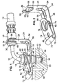
- FIG. 1 shows a holder for a pressure line 10, the one primarily of an elastomeric material existing hose section 12 and a metallic pipe part 14, wherein the tube section 12 with the tube part 14th by means of a per se known connector 16 e.g. by crimping connected is.
- a valve as a Cap screw 18 attached by means of the pressure line 10th at a pressure port 20 of a merely schematically illustrated Housing 22 e.g. a brake caliper connected fluid-tight can be.
- the holder has a preferably made of a spring band steel headband 24th with a first portion 26, by means of which the pressure line 10 on the connector 16 (or - alternatively - on the pipe part 14) and one with the first section 26 rigidly connected second section 28 to which the headband 24 with the aid of the cap screw 18 on the housing 22nd can be set, as will be described in more detail.
- the connector 16 of the pressure line 10 is at its the pipe part 14 facing end with a preferably elastic intermediate part 30 provided, which in the manner of a sleeve on the Pipe part 14 is seated and having a collar 32 in which on the outer circumference a circumferential groove 34 is introduced.
- the pipe part 14 in an arc by about 90 ° bent and extends through the cap screw 18 therethrough.
- the over the cap screw 18 in Fig. 1 down projecting free end 36 of the tubular member 14 is provided with a crimp 38 according to DIN 74 234 provided.
- the cap screw 18 is in the longitudinal direction of the pipe part 14th set, can be circumferentially with respect to the pipe part 14 but turn.
- Fig. 1 is further seen that the cap screw 18 has a handling portion 40 at for mounting the pressure line 10 to the housing 22 with a Spanner can be attacked.
- To the handling section 40 closes in Fig. 1 down a collar 42nd on.
- a fastening portion 44 which in the illustrated Embodiment with an external thread 46 is provided.
- the pressure port 20 of the housing 22 has an internal thread (not shown), in which the cap screw 18 with the External thread 46 of its mounting portion 44 screwed can be.
- the cap screw 18 In the screwed state of the cap screw 18th the flange 38 at the end 36 of the tubular member 14 is fluid-tight against a sealing cone 48 of the pressure port 20 is pressed.
- the housing 22 in Fig. 1 the sake of clarity on in Fig. 1 upper end is shown cut off. Actually lies in the mounted State of the pressure line 10 of the second portion 28 of the retaining clip 24 on the housing 22 at. In which the headband 24 facing Outer surface of the housing 22 is in the illustrated embodiment Finally, a blind bore 50 is introduced, the the inclusion of a pin 52 to prevent rotation of the retaining clip 24 serves.
- the first section 26 closes with the second section 28 a predetermined angle of about 90 °.
- the headband 24 in or on the transition area 54th between the first portion 26 and the second portion 28 with a in the longitudinal direction of the retaining clip 24th be provided extending profile 56.
- the first one has Section 26 of the retaining clip 24 at its free end 58 a undercut slot 60, which is a partially cylindrical Slot bottom 62 and joining bevels 64 has.
- the clear distance the transition areas 66 between the slot bottom 62 and the joining bevels 64 is for the formation of the undercut kept slightly smaller than the inner diameter of the Schlitzcampuss 62.
- a collar 68 is stamped on the first section 26 of the retaining clip 24 be around the inner peripheral surface of the slot bottom 62 in axial To increase direction.
- Condition of the retaining clip 24 is the intermediate part 30 of the connector 16 in the region of the groove 34 on the collar 32 in the slot 60 of the snapped in first portion 26 of the retaining clip 24 or in set the type of snap connection, as shown in FIG. 1.
- the headband 24 is in the state mounted on the housing 22 Pressure line 10 at its second portion 28 resiliently between the housing 22 and the cap screw 18 determines what the second portion 28 is resilient. More specifically, in the illustrated embodiment, the second section 28 of the retaining clip 24 at its from the first section 26 opposite end 70 via a cross-sectionally C-shaped Transition portion 72 in a respect to the second portion 28 by almost 180 ° angled spring tongue 74 on, the extending beyond half of the second section 28 in the direction the first section 26 advocateserstreckt. In Fig. 1 is the spring tongue 74, starting from the second section 28 upwards angled, a bending of the spring tongue down is in principle but also possible.
- the second section 28 is still substantially centered provided with a circular opening 76, with an oval Opening 78 at the end 80 of the spring tongue 74 in the longitudinal direction the first portion 26 of the retaining clip 24 aligned is.
- the opening 76 can be used to increase the axial length of its inner peripheral surface with an embossed Bund 82 be provided.
- This collar 82 prevents the second section 28 during assembly of the retaining clip 24 on the external thread 46 of the cap screw 18 can hang or serves to guide the second portion 28 of the retaining clip 24th on the cap screw 18 of the pressure line 10. As in Fig.
- the cap screw 18 extends with its attachment portion 44 in the pressure port 20 of the housing 22 mounted state of the pressure line 10 through the aligned Openings 76, 78 of the retaining clip 24 with low Radial clearance to the opening 76 therethrough.
- This is the spring tongue 74 of the retaining clip 24 resiliently on the annular collar 42 of the cap screw 18, while the second portion 28 of the retaining clip 24 resiliently against the headband 24 facing outer surface of the housing 22 is pressed.
- the result is the headband 24 with the spring tongue 74 and the second section 28 between the annular collar 42 of the cap screw 18 and the housing 22 elastic clamped or held with a defined biasing force.
- the cap screw 18 thus fulfills a dual function here; First, it presses the flange 38 at the end 36 of the Pipe part 14 in a fluid-tight contact with the sealing cone 48 am Pressure port 20 of the housing 22, on the other hand it spans the Bracket 24 at its second portion 28 elastically against the housing 22nd
- the second section 28 is substantially centered between the opening 76 and the transition portion 72 an opposite the opening 76 significantly smaller positioning hole 84th (See Fig. 1), which with a slot 86 in the spring tongue 74 is aligned.
- the cap screw 18 passes through the in the blind bore 50th of the housing 22 fixed pin 52, the positioning hole 84 in second portion 28 and the slot 86 in the spring tongue 74, around the headband 24 against rotation relative to the housing 22 to secure.
- both the opening 78 and the slot 86 of the spring tongue 74 to the attachment portion 44 of the cap screw 18 and to the pin 52 has a sufficient radial clearance, so, that neither the cap screw 18 nor the pin 52, the spring tongue 74 prevents feathers.
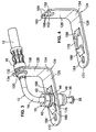
- FIGS. 3 and 4 second embodiment should be hereinafter referred to only in terms of its from the above first embodiment distinguishing features to be discribed.
- the above comments on the function or effect of the retaining clip 124 apply analogously.
- the headband 124 is opposite the headband 24 in total simplified trained. So are frets at the slot 160 and the opening 176 as well as a profiling between the first and second sections 126, 128 of the retaining clip 124 not intended. Instead of a spring tongue has the headband 124 in Fig. 4 issued upward spring arms 188 in the region of the opening 176 for the passage of the fastening portion 44 of Cap screw 18. These spring arms 188 are by introducing longitudinal slots on both sides of the opening 176 and then Bending up the cut-away parts of the second Section 128 of the retaining clip 124 is formed.
- the retaining bracket with respect to the housing also characterized be formed, that the second portion of the retaining clip with its sides positively in a complementary recess, e.g. a groove of the housing is received.
- FIG. 5 the second portion 228 of the retaining clip 224 at its remote from the first section 226 End 270 have a bent in the direction of the housing nose 290, in the assembled state of the retaining clip 224 in a corresponding recess of the housing engages.
- Fig. 6 is facing away from the first portion 326 of the retaining clip 324 End 370 of the second section 328 in total under training a step 392 downset deformed to the assembled state of the retaining clip 324 e.g. one edge of the housing form-fitting to reach behind.
- FIG. 7 shows a Variant in which the first section 426 of the retaining clip 424 opposite end 470 of the second portion 428 to about the Center cross-cut and the cut part of the end 470 is bent down to form a fold 494, wherein the fold 494 in the assembled state of the retaining clip 424, for example, a housing surface engages behind.
- FIGS. 8 to 11 should be in the following only in terms of his from the above-described embodiments distinguishing features to be discribed.
- the third one Embodiment of the holder first the pipe part 14 the Installation requirements accordingly more bent than the previous embodiments. Accordingly closes the second portion 528 of the retaining clip 524 with the vertically to the longitudinal axis of the connector 16 extending and - as FIGS. 8 and 11 show - towards the transition region 554 tapered first portion 526 of the retaining clip 524 a Angle greater than 90 °.
- the first portion 526 of the retaining clip 524 ends a limited by arms 596 slot 560 for receiving of the connector 16 mounted on the intermediate part 530.
- the Arms 596 preferably bear on the sides facing each other pointed projections or staples 597, which under plastic Bending the arms 596 toward each other for attachment of the intermediate part 530 on the mounting bracket 524 in the intermediate part 530 are depressible.
- the arms 596 are merely to simplify the presentation in undeformed State shown. A starting from the slot base 562 in Fig. 8 downwardly extending, further slot 598 provides in the rest that the arms 596 for fixing the intermediate part 530 on the bracket 524 sufficiently far inwardly bent can be.
- the second portion 528 of the retaining clip 524 is different designed as in the previously described embodiments.
- a torque arm here has the second section 528 first near the transition portion 572 to the spring tongue 574 as shown in FIGS. 9 and 11 issued a down Blechnase 590 on.
- the spring tongue 574 is relative to the second portion 528 of the holding bracket 524 angled by 180 °, so that the spring tongue 574 at least in the area of the spring tongue 574 formed opening 578 substantially parallel extends to the second portion 528 of the retaining clip 524.
- this is the first section 526 of the Holding bracket 524 facing end 580 of the spring tongue 574 in the direction the second portion 528 of the retaining clip 524, i. in Fig. 9 bent down and relies on the second section 528 from.
Landscapes
- Engineering & Computer Science (AREA)
- Mechanical Engineering (AREA)
- Transportation (AREA)
- General Engineering & Computer Science (AREA)
- Valves And Accessory Devices For Braking Systems (AREA)
- Clamps And Clips (AREA)
- Motor Or Generator Frames (AREA)
- Pens And Brushes (AREA)
- Rear-View Mirror Devices That Are Mounted On The Exterior Of The Vehicle (AREA)
Description
- Fig. 1
- eine perspektivische Ansicht eines ersten Ausführungsbeispiels einer erfindungsgemäßen Halterung für eine Druckleitung mit einem Haltebügel, wobei die Halterung in einer Einbausituation an einem schematisiert dargestellten Gehäuse gezeigt ist,
- Fig. 2
- eine perspektivische Ansicht des in Fig. 1 gezeigten Haltebügels,
- Fig. 3
- eine perspektivische Ansicht eines zweiten Ausführungsbeispiels einer erfindungsgemäßen Halterung für eine Druckleitung mit einem anderen Haltebügel, wobei der Haltebügel in einem an der Druckleitung vormontierten Zustand dargestellt ist,
- Fig. 4
- eine perspektivische Ansicht des in Fig. 3 gezeigten Haltebügels,
- Fig. 5 bis 7
- der Fig. 3 entsprechende perspektivische Ansichten von Varianten des zweiten Ausführungsbeispiels, die unterschiedliche Haltebügel aufweisen,
- Fig. 8
- eine perspektivische Ansicht eines dritten Ausführungsbeispiels einer erfindungsgemäßen Halterung für eine Druckleitung mit einem Haltebügel, der sich von den Haltebügeln der vorhergehenden Ausführungsbeispiele unterscheidet, wobei der Haltebügel in einem Zustand dargestellt ist, bevor er an der Druckleitung vormontiert wird,
- Fig. 9
- eine aufgebrochene Seitenansicht der in Fig. 8 gezeigten Halterung,
- Fig. 10
- eine Draufsicht auf die in Fig. 8 gezeigte Halterung von oben in Fig. 9 und
- Fig. 11
- eine Vorderansicht der in Fig. 8 gezeigten Halterung von links in Fig. 9.
- 10
- Druckleitung
- 12
- Schlauchabschnitt
- 14
- Rohrteil
- 16
- Verbinder
- 18
- Überwurfschraube
- 20
- Druckanschluß
- 22
- Gehäuse
- 24, 124, 224, 324, 424, 524
- Haltebügel
- 26, 126, 226, 326, 426, 526
- erster Abschnitt
- 28, 128, 228, 328, 428, 528
- zweiter Abschnitt
- 30, 130, 530
- Zwischenteil
- 32, 132
- Bund
- 34, 134
- Nut
- 36
- Ende
- 38
- Bördel
- 40
- Handhabungsabschnitt
- 42
- Ringbund
- 44
- Befestigungsabschnitt
- 46
- Außengewinde
- 48
- Dichtkegel
- 50
- Sackbohrung
- 52
- Stift
- 54, 154, 554
- Übergangsbereich
- 56
- Profilierung
- 58, 158
- Ende
- 60, 160, 560
- Schlitz
- 62, 162, 562
- Schlitzgrund
- 64, 164
- Fügeschräge
- 66, 166
- Übergangsbereich
- 68
- Bund
- 70, 170, 270, 370, 470, 570
- Ende
- 72, 572
- Übergangsabschnitt
- 74, 574
- Federzunge
- 76, 176, 576
- Öffnung
- 78, 578
- Öffnung
- 80, 580
- Ende
- 82
- Bund
- 84, 184
- Positionierloch
- 86
- Langloch
- 188
- Federarm
- 290, 590
- Nase
- 392
- Stufe
- 494
- Abkantung
- 595
- Fortsatz
- 596
- Arm
- 597
- Vorsprung
- 598
- Schlitz
Claims (11)
- Halterung für eine Druckleitung (10), mit
einer Druckleitung (10), insbesondere einer Bremsleitung, die ein mit einem Schlauchabschnitt (12) mittels eines Verbinders (16) verbundenes Rohrteil (14) aufweist, an dem eine Armatur (18) angebracht ist, und
einem Gehäuse (22), insbesondere einem Bremssattelgehäuse, das einen Druckanschluß (20) aufweist, an dem das Rohrteil (14) der Druckleitung (10) mittels der Armatur (18) angeschlossen ist,
gekennzeichnet durch einen Haltebügel (24, 124, 224, 324, 424, 524) mit
einem ersten Abschnitt (26, 126, 226, 326, 426, 526), mittels dessen die Druckleitung (10) an dem Verbinder (16) oder am Rohrteil (14) aufgelagert ist, und
einem mit dem ersten Abschnitt (26, 126, 226, 326, 426, 526) starr verbundenen zweiten Abschnitt (28, 128, 228, 328, 428, 528), an dem der Haltebügel (24, 124, 224, 324, 424, 524) mittels der Armatur (18) am Gehäuse (22) festgelegt ist,
wobei der Haltebügel (24, 124, 224, 324, 424, 524) an seinem zweiten Abschnitt (28, 128, 228, 328, 428, 528) zwischen der Armatur (18) der Druckleitung (10) und dem Gehäuse (22) federnd festgelegt ist, wozu der zweite Abschnitt (28, 128, 228, 328, 428, 528) des Haltebügels (24, 124, 224, 324, 424, 524) federnd ausgebildet ist. - Halterung nach Anspruch 1, dadurch gekennzeichnet, daß der erste Abschnitt (26, 126, 226, 326, 426) des Haltebügels (24, 124, 224, 324, 424) endseitig einen hinterschnittenen Schlitz (60, 160) aufweist, in dem der Verbinder (16) oder das Rohrteil (14) der Druckleitung (10) in der Art einer Schnappverbindung festgelegt ist.
- Halterung nach Anspruch 1, dadurch gekennzeichnet, daß der erste Abschnitt (526) des Haltebügels (524) endseitig einen von Armen (596) begrenzten Schlitz (560) zur Aufnahme eines am Verbinder (16) angebrachten Zwischenteils (530) aufweist, welches am Haltebügel (524) durch plastisches Biegen der Arme (596) kraft- und formschlüssig festgelegt ist.
- Halterung nach Anspruch 3, dadurch gekennzeichnet, daß das Zwischenteil (530) einen im wesentlichen U-förmigen Querschnitt aufweist und auf einen Fortsatz (595) des Verbinders (16) aufgeklipst ist.
- Halterung nach Anspruch 3 oder 4, dadurch gekennzeichnet, daß die Arme (596) am ersten Abschnitt (526) des Haltebügels (524) auf den einander zugewandten Seiten Vorsprünge (597) tragen, die unter plastischem Biegen der Arme (596) zur Festlegung des Zwischenteils (530) am Haltebügel (524) in das vorzugsweise aus Kunststoff bestehende Zwischenteil (530) eingedrückt sind.
- Halterung nach einem der vorhergehenden Ansprüche, dadurch gekennzeichnet, daß der zweite Abschnitt (28, 528) des Haltebügels (24, 524) eine Öffnung (76, 576) aufweist und an seinem vom ersten Abschnitt (26, 526) abgewandten Ende (70, 570) in eine abgewinkelte Federzunge (74, 574) übergeht, die eine weitere Öffnung (78, 578) hat, wobei sich die Armatur (18) der Druckleitung (10) im am Gehäuse (22) montierten Zustand durch die ausgefluchteten Öffnungen (76, 78; 576, 578) hindurch erstreckt, derart, daß der Haltebügel (24, 524) mit der Federzunge (74, 574) und dem zweiten Abschnitt (28, 528) zwischen einem Bund (42) der Armatur (18) und dem Gehäuse (22) federnd eingespannt ist.
- Halterung nach Anspruch 6, dadurch gekennzeichnet, daß das dem ersten Abschnitt (526) des Haltebügels (524) zugewandte Ende (580) der Federzunge (574) in Richtung des zweiten Abschnitts (528) des Haltebügels (524) abgekröpft ist und sich am zweiten Abschnitt (528) abstützt, wobei sich die Federzunge (574) im Bereich der in der Federzunge (574) ausgebildeten Öffnung (578) im wesentlichen parallel zum zweiten Abschnitt (528) des Haltebügels (524) erstreckt.
- Halterung nach einem der Ansprüche 1 bis 5, dadurch gekennzeichnet, daß der zweite Abschnitt (128) des Haltebügels (124) eine Öffnung (176) für die Armatur (18) der Druckleitung (10) aufweist, wobei im Bereich der Öffnung (176) ausgestellte Federarme (188) am zweiten Abschnitt (128) des Haltebügels (124) vorgesehen sind, die im am Gehäuse (22) montierten Zustand der Armatur (18) den Haltebügel (124) zwischen einem Bund (42) der Armatur (18) und dem Gehäuse (22) federnd einspannen.
- Halterung nach einem der vorhergehenden Ansprüche, dadurch gekennzeichnet, daß der Haltebügel (24, 124, 224, 324, 424, 524) im am Gehäuse (22) montierten Zustand der Armatur (18) der Druckleitung (10) gegen ein Verdrehen bezüglich des Gehäuses (22) gesichert ist, wozu der zweite Abschnitt des Haltebügels entweder formschlüssig in einer entsprechenden Aussparung des Gehäuses (22) sitzt oder ein Positionierloch (84, 184) hat, durch das sich ein am Gehäuse (22) festgelegter Stift (52) erstreckt, oder mit einer Abkantung (290, 370, 494, 590) versehen ist, die in eine Aussparung des Gehäuses (22) eingreift.
- Halterung nach einem der vorhergehenden Ansprüche, dadurch gekennzeichnet, daß das Rohrteil (14) gebogen ist und der erste Abschnitt (26, 126, 226, 326, 426, 526) mit dem zweiten Abschnitt (28, 128, 228, 328, 428, 528) des Haltebügels (24, 124, 224, 324, 424, 524) einen vorbestimmten Winkel einschließt, wobei der Haltebügel (24) zur Aussteifung im Übergangsbereich (54) zwischen dem ersten Abschnitt (26) und dem zweiten Abschnitt (28) vorzugsweise mit einer Profilierung (56) versehen ist.
- Halterung nach einem der vorhergehenden Ansprüche, dadurch gekennzeichnet, daß der Haltebügel (24, 124, 224, 324, 424, 524) aus einem Federbandstahl besteht.
Applications Claiming Priority (2)
| Application Number | Priority Date | Filing Date | Title |
|---|---|---|---|
| DE19944600 | 1999-09-16 | ||
| DE19944600A DE19944600A1 (de) | 1999-09-16 | 1999-09-16 | Halterung für eine Druckleitung |
Publications (3)
| Publication Number | Publication Date |
|---|---|
| EP1084926A2 EP1084926A2 (de) | 2001-03-21 |
| EP1084926A3 EP1084926A3 (de) | 2002-11-27 |
| EP1084926B1 true EP1084926B1 (de) | 2004-03-24 |
Family
ID=7922371
Family Applications (1)
| Application Number | Title | Priority Date | Filing Date |
|---|---|---|---|
| EP00119523A Expired - Lifetime EP1084926B1 (de) | 1999-09-16 | 2000-09-07 | Halterung für eine Druckleitung |
Country Status (4)
| Country | Link |
|---|---|
| US (1) | US6769652B1 (de) |
| EP (1) | EP1084926B1 (de) |
| AT (1) | ATE262435T1 (de) |
| DE (2) | DE19944600A1 (de) |
Families Citing this family (17)
| Publication number | Priority date | Publication date | Assignee | Title |
|---|---|---|---|---|
| US20040182971A1 (en) * | 2003-03-18 | 2004-09-23 | Manish Sharma | Fiber optic connector bracket |
| JP4184886B2 (ja) * | 2003-08-19 | 2008-11-19 | 本田技研工業株式会社 | 自動二輪車のabs油圧ユニット組立体の取付構造 |
| DE202004008388U1 (de) | 2004-05-26 | 2004-08-05 | Böllhoff Verbindungstechnik GmbH | Verbindungsanordnung aus Kunststoff zum Festlegen eines Schlauches |
| DE102005061903A1 (de) * | 2005-12-23 | 2007-06-28 | Gustav Magenwirth Gmbh & Co. Kg | Anschlussstück und Bremszange |
| US20080093182A1 (en) * | 2006-10-04 | 2008-04-24 | Bernhardt Goettker | Apparatus and Method for Connecting Hydraulic Brake Lines to Brake Assemblies on Towed Trailers |
| DE102008015172A1 (de) * | 2008-03-20 | 2009-09-24 | Dr. Ing. H.C. F. Porsche Aktiengesellschaft | Halter |
| WO2011088297A1 (en) * | 2010-01-15 | 2011-07-21 | Afl Telecommunications Llc | Cable tie-down bracket |
| EP2354615B1 (de) * | 2010-02-05 | 2012-08-22 | Centrotherm Systemtechnik GmbH | Sicherungsvorrichtung einer Fluidleitungsverbindung |
| SE534909C2 (sv) * | 2010-06-14 | 2012-02-14 | Scania Cv Ab | Ledningshållaranordning |
| US8899533B2 (en) | 2013-01-16 | 2014-12-02 | Honda Motor Co., Ltd. | Vehicle hydraulic brake hose assembly |
| US9677691B2 (en) * | 2013-04-29 | 2017-06-13 | The Reliable Automatic Sprinkler Company | Sprinkler fitting bracket |
| US9791096B2 (en) | 2015-05-07 | 2017-10-17 | Hamilton Sundstrand Corporation | Anti-rotation bracket |
| JP6418198B2 (ja) * | 2016-04-25 | 2018-11-07 | 株式会社豊田自動織機 | 車両のブレーキホースの支持構造 |
| CN109812522B (zh) * | 2017-11-22 | 2020-11-13 | 江苏恒力制动器制造有限公司 | 一种传感器接头锁止机构 |
| DE102018114858A1 (de) * | 2018-06-20 | 2019-12-24 | Volkswagen Aktiengesellschaft | Rohrhalterung und Kraftfahrzeug mit einer derartigen Rohrhalterung |
| US11091363B1 (en) * | 2020-05-08 | 2021-08-17 | Camco Manufacturing, Inc. | Hands-free tank fill device |
| CN111997891B (zh) * | 2020-09-10 | 2022-08-19 | 康斯克泵业(苏州)有限公司 | 一种液压泵吸油管的插接机构 |
Family Cites Families (19)
| Publication number | Priority date | Publication date | Assignee | Title |
|---|---|---|---|---|
| US2432492A (en) * | 1942-05-09 | 1947-12-09 | Tinnerman Products Inc | Combined nut fastener and grounding member |
| DE1955504A1 (de) * | 1969-11-04 | 1971-05-13 | Kugelfischer G Schaefer & Co | Bremsschlauchanschluss |
| GB1389448A (en) * | 1971-04-20 | 1975-04-03 | United Carr Ltd | Fastener |
| DE2435995A1 (de) * | 1974-07-26 | 1976-02-12 | Lapp Kg U I | Einteilige, verdrehungsgesicherte schelle mit unverlierbarer schraube |
| DE2600725C2 (de) * | 1976-01-09 | 1982-08-05 | Volkswagenwerk Ag, 3180 Wolfsburg | Aus einem Federstahlstreifen gebildete Haltefeder |
| US4005942A (en) * | 1976-03-22 | 1977-02-01 | Simpson Manufacturing Co., Inc. | Metal hanger |
| US4074491A (en) * | 1976-10-26 | 1978-02-21 | The Boeing Company | Clip shock mount |
| US4189807A (en) * | 1976-11-15 | 1980-02-26 | Viking Industries, Inc. | Clamp |
| DE3004421C2 (de) * | 1980-02-07 | 1981-11-26 | Adam Opel AG, 6090 Rüsselsheim | Befestigungsvorrichtung für einen Bremsschlauch |
| US4340244A (en) * | 1980-09-22 | 1982-07-20 | Scott Kenneth W | Clip for slip-joint tube connections |
| JPS60169496U (ja) * | 1984-04-20 | 1985-11-09 | 豊田合成株式会社 | ホ−ス継手 |
| DE8634435U1 (de) * | 1986-12-23 | 1987-02-12 | REHAU AG + Co, 8673 Rehau | Rohrführungsbogen |
| US5178479A (en) * | 1990-06-25 | 1993-01-12 | Illinois Tool Works Inc. | Rod end clip |
| DE4039822C1 (de) * | 1990-12-13 | 1992-07-23 | A. Raymond Kg, 7850 Loerrach, De | |
| DE4230889B4 (de) * | 1992-09-16 | 2007-08-16 | Continental Teves Ag & Co. Ohg | Wärmegeschützter Anschluß einer Bremsleitung an ein Bremsengehäuse |
| GB2284005B (en) * | 1993-11-20 | 1997-01-08 | Graham Charles Taylor | A glazed unit |
| DE9401393U1 (de) * | 1994-01-27 | 1994-05-19 | Emhart Inc., Newark, Del. | Schwingungsdämpfender Leitungshalter |
| DE19544222A1 (de) * | 1995-11-28 | 1997-06-05 | Bosch Gmbh Robert | Vorrichtung zum Anschließen einer Fluidleitung an ein fluidführendes Bauteil |
| DE29909715U1 (de) * | 1999-06-04 | 1999-09-02 | Anton Hummel Verwaltungs Gmbh, 79183 Waldkirch | Wellschlauch mit einer Halterung |
-
1999
- 1999-09-16 DE DE19944600A patent/DE19944600A1/de not_active Withdrawn
-
2000
- 2000-09-07 AT AT00119523T patent/ATE262435T1/de not_active IP Right Cessation
- 2000-09-07 DE DE50005772T patent/DE50005772D1/de not_active Expired - Lifetime
- 2000-09-07 EP EP00119523A patent/EP1084926B1/de not_active Expired - Lifetime
- 2000-09-13 US US09/661,174 patent/US6769652B1/en not_active Expired - Lifetime
Also Published As
| Publication number | Publication date |
|---|---|
| ATE262435T1 (de) | 2004-04-15 |
| US6769652B1 (en) | 2004-08-03 |
| DE19944600A1 (de) | 2001-04-05 |
| DE50005772D1 (de) | 2004-04-29 |
| EP1084926A2 (de) | 2001-03-21 |
| EP1084926A3 (de) | 2002-11-27 |
Similar Documents
| Publication | Publication Date | Title |
|---|---|---|
| DE10162657B4 (de) | Anschlussstück für Fluidleitungen sowie damit ausgestattetes fluidtechnisches Gerät | |
| EP0618385B1 (de) | Schallentkoppelndes Verbindungselement | |
| DE19526833B4 (de) | Schnellspannsystem | |
| EP1084926A2 (de) | Halterung für eine Druckleitung | |
| DE4236481C2 (de) | Rückschlagventil | |
| DE10336351B3 (de) | Rohrschelle | |
| EP1635103B1 (de) | Lösbare Steckverbindung für Rohrleitungen od. dgl. | |
| EP2712413B1 (de) | Anschlussvorrichtung zum anschliessen einer fluidleitung | |
| DE69329881T2 (de) | Rohrkupplung | |
| EP1319451A1 (de) | Stutzen für ein Wandteil, insbesondere für ein Wandteil eines Deckels oder Behälters | |
| EP1888960B1 (de) | Verankerungselement für rohrkupplungen | |
| WO2017148699A1 (de) | Profilschelle | |
| EP0813665A1 (de) | Dichtungselement für einen aus einer hohlschraube und einem ringstutzen bestehenden hydraulischen schraubanschluss | |
| EP0717225A1 (de) | Vorrichtung zur Verbindung von zwei rohrförmigen Leitungsteilen | |
| DE10147141A1 (de) | Abgedichtete, verstellbare und selbsthemmende Schraubverbindung | |
| DE102007015131A1 (de) | Verbindungsanordnung und Arretierung für eine Verbindungsanordnung | |
| EP0790423A1 (de) | Verfahren zur Herstellung einer Vorrichtung zum Verbinden eines kerbverzahnten, der Übertragung von Drehmomenten dienenden Wellenzapfens | |
| EP1314921A2 (de) | Rohrbruchventil | |
| DE19509920A1 (de) | Winkelgelenk | |
| DE60306786T2 (de) | Schnellverbindung für einen mit gewinde versehener fluidbauteil | |
| EP1446587B1 (de) | Gelenk | |
| DE102005029529B4 (de) | Verbindungsvorrichtung zur Befestigung von Bauteilen | |
| EP0451739A2 (de) | Kupplungsstück | |
| EP2082144A1 (de) | Kombination aus einer schraube und einer hülse sowie verfahren zum herstellen einer solchen kombination | |
| EP1930642A2 (de) | Sicherungselement |
Legal Events
| Date | Code | Title | Description |
|---|---|---|---|
| PUAI | Public reference made under article 153(3) epc to a published international application that has entered the european phase |
Free format text: ORIGINAL CODE: 0009012 |
|
| AK | Designated contracting states |
Kind code of ref document: A2 Designated state(s): AT BE CH CY DE DK ES FI FR GB GR IE IT LI LU MC NL PT SE |
|
| AX | Request for extension of the european patent |
Free format text: AL;LT;LV;MK;RO;SI |
|
| RIC1 | Information provided on ipc code assigned before grant |
Free format text: 7B 60T 17/04 A, 7F 16L 3/00 B |
|
| PUAL | Search report despatched |
Free format text: ORIGINAL CODE: 0009013 |
|
| AK | Designated contracting states |
Kind code of ref document: A3 Designated state(s): AT BE CH CY DE DK ES FI FR GB GR IE IT LI LU MC NL PT SE |
|
| AX | Request for extension of the european patent |
Free format text: AL;LT;LV;MK;RO;SI |
|
| 17P | Request for examination filed |
Effective date: 20030117 |
|
| 17Q | First examination report despatched |
Effective date: 20030313 |
|
| AKX | Designation fees paid |
Designated state(s): AT BE CH CY DE DK ES FI FR GB GR IE IT LI LU MC NL PT SE |
|
| GRAP | Despatch of communication of intention to grant a patent |
Free format text: ORIGINAL CODE: EPIDOSNIGR1 |
|
| GRAS | Grant fee paid |
Free format text: ORIGINAL CODE: EPIDOSNIGR3 |
|
| GRAA | (expected) grant |
Free format text: ORIGINAL CODE: 0009210 |
|
| RAP1 | Party data changed (applicant data changed or rights of an application transferred) |
Owner name: FTEAUTOMOTIVE GMBH & CO. KG |
|
| AK | Designated contracting states |
Kind code of ref document: B1 Designated state(s): AT BE CH CY DE DK ES FI FR GB GR IE IT LI LU MC NL PT SE |
|
| PG25 | Lapsed in a contracting state [announced via postgrant information from national office to epo] |
Ref country code: IE Free format text: LAPSE BECAUSE OF FAILURE TO SUBMIT A TRANSLATION OF THE DESCRIPTION OR TO PAY THE FEE WITHIN THE PRESCRIBED TIME-LIMIT Effective date: 20040324 Ref country code: FI Free format text: LAPSE BECAUSE OF FAILURE TO SUBMIT A TRANSLATION OF THE DESCRIPTION OR TO PAY THE FEE WITHIN THE PRESCRIBED TIME-LIMIT Effective date: 20040324 Ref country code: CY Free format text: LAPSE BECAUSE OF FAILURE TO SUBMIT A TRANSLATION OF THE DESCRIPTION OR TO PAY THE FEE WITHIN THE PRESCRIBED TIME-LIMIT Effective date: 20040324 Ref country code: NL Free format text: LAPSE BECAUSE OF FAILURE TO SUBMIT A TRANSLATION OF THE DESCRIPTION OR TO PAY THE FEE WITHIN THE PRESCRIBED TIME-LIMIT Effective date: 20040324 |
|
| REG | Reference to a national code |
Ref country code: GB Ref legal event code: FG4D Free format text: NOT ENGLISH |
|
| REG | Reference to a national code |
Ref country code: CH Ref legal event code: EP |
|
| REG | Reference to a national code |
Ref country code: IE Ref legal event code: FG4D Free format text: GERMAN |
|
| REF | Corresponds to: |
Ref document number: 50005772 Country of ref document: DE Date of ref document: 20040429 Kind code of ref document: P |
|
| GBT | Gb: translation of ep patent filed (gb section 77(6)(a)/1977) |
Effective date: 20040512 |
|
| PG25 | Lapsed in a contracting state [announced via postgrant information from national office to epo] |
Ref country code: SE Free format text: LAPSE BECAUSE OF FAILURE TO SUBMIT A TRANSLATION OF THE DESCRIPTION OR TO PAY THE FEE WITHIN THE PRESCRIBED TIME-LIMIT Effective date: 20040624 Ref country code: GR Free format text: LAPSE BECAUSE OF FAILURE TO SUBMIT A TRANSLATION OF THE DESCRIPTION OR TO PAY THE FEE WITHIN THE PRESCRIBED TIME-LIMIT Effective date: 20040624 Ref country code: DK Free format text: LAPSE BECAUSE OF FAILURE TO SUBMIT A TRANSLATION OF THE DESCRIPTION OR TO PAY THE FEE WITHIN THE PRESCRIBED TIME-LIMIT Effective date: 20040624 |
|
| PG25 | Lapsed in a contracting state [announced via postgrant information from national office to epo] |
Ref country code: ES Free format text: LAPSE BECAUSE OF FAILURE TO SUBMIT A TRANSLATION OF THE DESCRIPTION OR TO PAY THE FEE WITHIN THE PRESCRIBED TIME-LIMIT Effective date: 20040705 |
|
| NLV1 | Nl: lapsed or annulled due to failure to fulfill the requirements of art. 29p and 29m of the patents act | ||
| PG25 | Lapsed in a contracting state [announced via postgrant information from national office to epo] |
Ref country code: LU Free format text: LAPSE BECAUSE OF NON-PAYMENT OF DUE FEES Effective date: 20040907 Ref country code: AT Free format text: LAPSE BECAUSE OF NON-PAYMENT OF DUE FEES Effective date: 20040907 |
|
| PG25 | Lapsed in a contracting state [announced via postgrant information from national office to epo] |
Ref country code: CH Free format text: LAPSE BECAUSE OF NON-PAYMENT OF DUE FEES Effective date: 20040930 Ref country code: LI Free format text: LAPSE BECAUSE OF NON-PAYMENT OF DUE FEES Effective date: 20040930 Ref country code: BE Free format text: LAPSE BECAUSE OF NON-PAYMENT OF DUE FEES Effective date: 20040930 Ref country code: MC Free format text: LAPSE BECAUSE OF NON-PAYMENT OF DUE FEES Effective date: 20040930 |
|
| REG | Reference to a national code |
Ref country code: IE Ref legal event code: FD4D |
|
| ET | Fr: translation filed | ||
| PLBE | No opposition filed within time limit |
Free format text: ORIGINAL CODE: 0009261 |
|
| STAA | Information on the status of an ep patent application or granted ep patent |
Free format text: STATUS: NO OPPOSITION FILED WITHIN TIME LIMIT |
|
| 26N | No opposition filed |
Effective date: 20041228 |
|
| BERE | Be: lapsed |
Owner name: *FTE AUTOMOTIVE G.M.B.H. & CO. K.G. Effective date: 20040930 |
|
| REG | Reference to a national code |
Ref country code: CH Ref legal event code: PL |
|
| REG | Reference to a national code |
Ref country code: GB Ref legal event code: 732E |
|
| REG | Reference to a national code |
Ref country code: FR Ref legal event code: TP Ref country code: FR Ref legal event code: CD |
|
| BERE | Be: lapsed |
Owner name: *FTE AUTOMOTIVE G.M.B.H. & CO. K.G. Effective date: 20040930 |
|
| PG25 | Lapsed in a contracting state [announced via postgrant information from national office to epo] |
Ref country code: PT Free format text: LAPSE BECAUSE OF NON-PAYMENT OF DUE FEES Effective date: 20040824 |
|
| PGFP | Annual fee paid to national office [announced via postgrant information from national office to epo] |
Ref country code: FR Payment date: 20080702 Year of fee payment: 9 Ref country code: IT Payment date: 20080926 Year of fee payment: 9 |
|
| PGFP | Annual fee paid to national office [announced via postgrant information from national office to epo] |
Ref country code: GB Payment date: 20080911 Year of fee payment: 9 |
|
| GBPC | Gb: european patent ceased through non-payment of renewal fee |
Effective date: 20090907 |
|
| REG | Reference to a national code |
Ref country code: FR Ref legal event code: ST Effective date: 20100531 |
|
| PG25 | Lapsed in a contracting state [announced via postgrant information from national office to epo] |
Ref country code: FR Free format text: LAPSE BECAUSE OF NON-PAYMENT OF DUE FEES Effective date: 20090930 |
|
| PG25 | Lapsed in a contracting state [announced via postgrant information from national office to epo] |
Ref country code: GB Free format text: LAPSE BECAUSE OF NON-PAYMENT OF DUE FEES Effective date: 20090907 |
|
| PG25 | Lapsed in a contracting state [announced via postgrant information from national office to epo] |
Ref country code: IT Free format text: LAPSE BECAUSE OF NON-PAYMENT OF DUE FEES Effective date: 20090907 |
|
| PGFP | Annual fee paid to national office [announced via postgrant information from national office to epo] |
Ref country code: DE Payment date: 20170914 Year of fee payment: 18 |
|
| REG | Reference to a national code |
Ref country code: DE Ref legal event code: R119 Ref document number: 50005772 Country of ref document: DE |
|
| PG25 | Lapsed in a contracting state [announced via postgrant information from national office to epo] |
Ref country code: DE Free format text: LAPSE BECAUSE OF NON-PAYMENT OF DUE FEES Effective date: 20190402 |