EP1084747A1 - Vorrichtung zur Durchführung einer heterogen katalysierten Reaktion und Verfahren zu deren Herstellung - Google Patents
Vorrichtung zur Durchführung einer heterogen katalysierten Reaktion und Verfahren zu deren Herstellung Download PDFInfo
- Publication number
- EP1084747A1 EP1084747A1 EP00116572A EP00116572A EP1084747A1 EP 1084747 A1 EP1084747 A1 EP 1084747A1 EP 00116572 A EP00116572 A EP 00116572A EP 00116572 A EP00116572 A EP 00116572A EP 1084747 A1 EP1084747 A1 EP 1084747A1
- Authority
- EP
- European Patent Office
- Prior art keywords
- layers
- catalyst
- edge seal
- gas
- reaction mixture
- Prior art date
- Legal status (The legal status is an assumption and is not a legal conclusion. Google has not performed a legal analysis and makes no representation as to the accuracy of the status listed.)
- Granted
Links
Images

Classifications
-
- H—ELECTRICITY
- H01—ELECTRIC ELEMENTS
- H01M—PROCESSES OR MEANS, e.g. BATTERIES, FOR THE DIRECT CONVERSION OF CHEMICAL ENERGY INTO ELECTRICAL ENERGY
- H01M8/00—Fuel cells; Manufacture thereof
- H01M8/06—Combination of fuel cells with means for production of reactants or for treatment of residues
- H01M8/0606—Combination of fuel cells with means for production of reactants or for treatment of residues with means for production of gaseous reactants
- H01M8/0612—Combination of fuel cells with means for production of reactants or for treatment of residues with means for production of gaseous reactants from carbon-containing material
- H01M8/0625—Combination of fuel cells with means for production of reactants or for treatment of residues with means for production of gaseous reactants from carbon-containing material in a modular combined reactor/fuel cell structure
- H01M8/0631—Reactor construction specially adapted for combination reactor/fuel cell
-
- B—PERFORMING OPERATIONS; TRANSPORTING
- B01—PHYSICAL OR CHEMICAL PROCESSES OR APPARATUS IN GENERAL
- B01J—CHEMICAL OR PHYSICAL PROCESSES, e.g. CATALYSIS OR COLLOID CHEMISTRY; THEIR RELEVANT APPARATUS
- B01J12/00—Chemical processes in general for reacting gaseous media with gaseous media; Apparatus specially adapted therefor
- B01J12/007—Chemical processes in general for reacting gaseous media with gaseous media; Apparatus specially adapted therefor in the presence of catalytically active bodies, e.g. porous plates
-
- B—PERFORMING OPERATIONS; TRANSPORTING
- B01—PHYSICAL OR CHEMICAL PROCESSES OR APPARATUS IN GENERAL
- B01J—CHEMICAL OR PHYSICAL PROCESSES, e.g. CATALYSIS OR COLLOID CHEMISTRY; THEIR RELEVANT APPARATUS
- B01J15/00—Chemical processes in general for reacting gaseous media with non-particulate solids, e.g. sheet material; Apparatus specially adapted therefor
- B01J15/005—Chemical processes in general for reacting gaseous media with non-particulate solids, e.g. sheet material; Apparatus specially adapted therefor in the presence of catalytically active bodies, e.g. porous plates
-
- B—PERFORMING OPERATIONS; TRANSPORTING
- B01—PHYSICAL OR CHEMICAL PROCESSES OR APPARATUS IN GENERAL
- B01J—CHEMICAL OR PHYSICAL PROCESSES, e.g. CATALYSIS OR COLLOID CHEMISTRY; THEIR RELEVANT APPARATUS
- B01J19/00—Chemical, physical or physico-chemical processes in general; Their relevant apparatus
- B01J19/24—Stationary reactors without moving elements inside
- B01J19/248—Reactors comprising multiple separated flow channels
- B01J19/249—Plate-type reactors
-
- B—PERFORMING OPERATIONS; TRANSPORTING
- B01—PHYSICAL OR CHEMICAL PROCESSES OR APPARATUS IN GENERAL
- B01J—CHEMICAL OR PHYSICAL PROCESSES, e.g. CATALYSIS OR COLLOID CHEMISTRY; THEIR RELEVANT APPARATUS
- B01J35/00—Catalysts, in general, characterised by their form or physical properties
- B01J35/50—Catalysts, in general, characterised by their form or physical properties characterised by their shape or configuration
- B01J35/56—Foraminous structures having flow-through passages or channels, e.g. grids or three-dimensional [3D] monoliths
-
- C—CHEMISTRY; METALLURGY
- C01—INORGANIC CHEMISTRY
- C01B—NON-METALLIC ELEMENTS; COMPOUNDS THEREOF; METALLOIDS OR COMPOUNDS THEREOF NOT COVERED BY SUBCLASS C01C
- C01B3/00—Hydrogen; Gaseous mixtures containing hydrogen; Separation of hydrogen from mixtures containing it; Purification of hydrogen; Reversible storage of hydrogen
- C01B3/02—Production of hydrogen; Production of gaseous mixtures containing hydrogen
- C01B3/06—Production of hydrogen; Production of gaseous mixtures containing hydrogen by reaction of inorganic compounds containing electro-positively bound hydrogen with inorganic reducing agents
- C01B3/12—Production of hydrogen; Production of gaseous mixtures containing hydrogen by reaction of inorganic compounds containing electro-positively bound hydrogen with inorganic reducing agents by reaction of water vapour with carbon monoxide
- C01B3/16—Production of hydrogen; Production of gaseous mixtures containing hydrogen by reaction of inorganic compounds containing electro-positively bound hydrogen with inorganic reducing agents by reaction of water vapour with carbon monoxide using catalysts
-
- C—CHEMISTRY; METALLURGY
- C01—INORGANIC CHEMISTRY
- C01B—NON-METALLIC ELEMENTS; COMPOUNDS THEREOF; METALLOIDS OR COMPOUNDS THEREOF NOT COVERED BY SUBCLASS C01C
- C01B3/00—Hydrogen; Gaseous mixtures containing hydrogen; Separation of hydrogen from mixtures containing it; Purification of hydrogen; Reversible storage of hydrogen
- C01B3/02—Production of hydrogen; Production of gaseous mixtures containing hydrogen
- C01B3/32—Production of hydrogen; Production of gaseous mixtures containing hydrogen by reaction of gaseous or liquid organic compounds with gasifying agents, e.g. water, carbon dioxide or air
- C01B3/323—Catalytic reaction of gaseous or liquid organic compounds other than hydrocarbons with gasifying agents
-
- C—CHEMISTRY; METALLURGY
- C01—INORGANIC CHEMISTRY
- C01B—NON-METALLIC ELEMENTS; COMPOUNDS THEREOF; METALLOIDS OR COMPOUNDS THEREOF NOT COVERED BY SUBCLASS C01C
- C01B3/00—Hydrogen; Gaseous mixtures containing hydrogen; Separation of hydrogen from mixtures containing it; Purification of hydrogen; Reversible storage of hydrogen
- C01B3/50—Separation of hydrogen or hydrogen-containing gases from gaseous mixtures, e.g. purification
- C01B3/56—Separation of hydrogen or hydrogen-containing gases from gaseous mixtures, e.g. purification by contacting with solids; Regeneration of used solids
- C01B3/58—Separation of hydrogen or hydrogen-containing gases from gaseous mixtures, e.g. purification by contacting with solids; Regeneration of used solids including a catalytic reaction
- C01B3/583—Separation of hydrogen or hydrogen-containing gases from gaseous mixtures, e.g. purification by contacting with solids; Regeneration of used solids including a catalytic reaction the reaction being the selective oxidation of carbon monoxide
-
- B—PERFORMING OPERATIONS; TRANSPORTING
- B01—PHYSICAL OR CHEMICAL PROCESSES OR APPARATUS IN GENERAL
- B01J—CHEMICAL OR PHYSICAL PROCESSES, e.g. CATALYSIS OR COLLOID CHEMISTRY; THEIR RELEVANT APPARATUS
- B01J2219/00—Chemical, physical or physico-chemical processes in general; Their relevant apparatus
- B01J2219/24—Stationary reactors without moving elements inside
- B01J2219/2401—Reactors comprising multiple separate flow channels
- B01J2219/245—Plate-type reactors
- B01J2219/2451—Geometry of the reactor
- B01J2219/2453—Plates arranged in parallel
-
- B—PERFORMING OPERATIONS; TRANSPORTING
- B01—PHYSICAL OR CHEMICAL PROCESSES OR APPARATUS IN GENERAL
- B01J—CHEMICAL OR PHYSICAL PROCESSES, e.g. CATALYSIS OR COLLOID CHEMISTRY; THEIR RELEVANT APPARATUS
- B01J2219/00—Chemical, physical or physico-chemical processes in general; Their relevant apparatus
- B01J2219/24—Stationary reactors without moving elements inside
- B01J2219/2401—Reactors comprising multiple separate flow channels
- B01J2219/245—Plate-type reactors
- B01J2219/2451—Geometry of the reactor
- B01J2219/2456—Geometry of the plates
-
- B—PERFORMING OPERATIONS; TRANSPORTING
- B01—PHYSICAL OR CHEMICAL PROCESSES OR APPARATUS IN GENERAL
- B01J—CHEMICAL OR PHYSICAL PROCESSES, e.g. CATALYSIS OR COLLOID CHEMISTRY; THEIR RELEVANT APPARATUS
- B01J2219/00—Chemical, physical or physico-chemical processes in general; Their relevant apparatus
- B01J2219/24—Stationary reactors without moving elements inside
- B01J2219/2401—Reactors comprising multiple separate flow channels
- B01J2219/245—Plate-type reactors
- B01J2219/2476—Construction materials
- B01J2219/2477—Construction materials of the catalysts
- B01J2219/2479—Catalysts coated on the surface of plates or inserts
-
- B—PERFORMING OPERATIONS; TRANSPORTING
- B01—PHYSICAL OR CHEMICAL PROCESSES OR APPARATUS IN GENERAL
- B01J—CHEMICAL OR PHYSICAL PROCESSES, e.g. CATALYSIS OR COLLOID CHEMISTRY; THEIR RELEVANT APPARATUS
- B01J2219/00—Chemical, physical or physico-chemical processes in general; Their relevant apparatus
- B01J2219/24—Stationary reactors without moving elements inside
- B01J2219/2401—Reactors comprising multiple separate flow channels
- B01J2219/245—Plate-type reactors
- B01J2219/2476—Construction materials
- B01J2219/2477—Construction materials of the catalysts
- B01J2219/2482—Catalytically active foils; Plates having catalytically activity on their own
-
- B—PERFORMING OPERATIONS; TRANSPORTING
- B01—PHYSICAL OR CHEMICAL PROCESSES OR APPARATUS IN GENERAL
- B01J—CHEMICAL OR PHYSICAL PROCESSES, e.g. CATALYSIS OR COLLOID CHEMISTRY; THEIR RELEVANT APPARATUS
- B01J2219/00—Chemical, physical or physico-chemical processes in general; Their relevant apparatus
- B01J2219/24—Stationary reactors without moving elements inside
- B01J2219/2401—Reactors comprising multiple separate flow channels
- B01J2219/245—Plate-type reactors
- B01J2219/2491—Other constructional details
- B01J2219/2492—Assembling means
- B01J2219/2493—Means for assembling plates together, e.g. sealing means, screws, bolts
-
- B—PERFORMING OPERATIONS; TRANSPORTING
- B01—PHYSICAL OR CHEMICAL PROCESSES OR APPARATUS IN GENERAL
- B01J—CHEMICAL OR PHYSICAL PROCESSES, e.g. CATALYSIS OR COLLOID CHEMISTRY; THEIR RELEVANT APPARATUS
- B01J37/00—Processes, in general, for preparing catalysts; Processes, in general, for activation of catalysts
- B01J37/0009—Use of binding agents; Moulding; Pressing; Powdering; Granulating; Addition of materials ameliorating the mechanical properties of the product catalyst
-
- C—CHEMISTRY; METALLURGY
- C01—INORGANIC CHEMISTRY
- C01B—NON-METALLIC ELEMENTS; COMPOUNDS THEREOF; METALLOIDS OR COMPOUNDS THEREOF NOT COVERED BY SUBCLASS C01C
- C01B2203/00—Integrated processes for the production of hydrogen or synthesis gas
- C01B2203/04—Integrated processes for the production of hydrogen or synthesis gas containing a purification step for the hydrogen or the synthesis gas
- C01B2203/0435—Catalytic purification
- C01B2203/044—Selective oxidation of carbon monoxide
-
- C—CHEMISTRY; METALLURGY
- C01—INORGANIC CHEMISTRY
- C01B—NON-METALLIC ELEMENTS; COMPOUNDS THEREOF; METALLOIDS OR COMPOUNDS THEREOF NOT COVERED BY SUBCLASS C01C
- C01B2203/00—Integrated processes for the production of hydrogen or synthesis gas
- C01B2203/04—Integrated processes for the production of hydrogen or synthesis gas containing a purification step for the hydrogen or the synthesis gas
- C01B2203/0465—Composition of the impurity
- C01B2203/047—Composition of the impurity the impurity being carbon monoxide
-
- Y—GENERAL TAGGING OF NEW TECHNOLOGICAL DEVELOPMENTS; GENERAL TAGGING OF CROSS-SECTIONAL TECHNOLOGIES SPANNING OVER SEVERAL SECTIONS OF THE IPC; TECHNICAL SUBJECTS COVERED BY FORMER USPC CROSS-REFERENCE ART COLLECTIONS [XRACs] AND DIGESTS
- Y02—TECHNOLOGIES OR APPLICATIONS FOR MITIGATION OR ADAPTATION AGAINST CLIMATE CHANGE
- Y02E—REDUCTION OF GREENHOUSE GAS [GHG] EMISSIONS, RELATED TO ENERGY GENERATION, TRANSMISSION OR DISTRIBUTION
- Y02E60/00—Enabling technologies; Technologies with a potential or indirect contribution to GHG emissions mitigation
- Y02E60/30—Hydrogen technology
- Y02E60/50—Fuel cells
-
- Y—GENERAL TAGGING OF NEW TECHNOLOGICAL DEVELOPMENTS; GENERAL TAGGING OF CROSS-SECTIONAL TECHNOLOGIES SPANNING OVER SEVERAL SECTIONS OF THE IPC; TECHNICAL SUBJECTS COVERED BY FORMER USPC CROSS-REFERENCE ART COLLECTIONS [XRACs] AND DIGESTS
- Y02—TECHNOLOGIES OR APPLICATIONS FOR MITIGATION OR ADAPTATION AGAINST CLIMATE CHANGE
- Y02P—CLIMATE CHANGE MITIGATION TECHNOLOGIES IN THE PRODUCTION OR PROCESSING OF GOODS
- Y02P20/00—Technologies relating to chemical industry
- Y02P20/50—Improvements relating to the production of bulk chemicals
- Y02P20/52—Improvements relating to the production of bulk chemicals using catalysts, e.g. selective catalysts
-
- Y—GENERAL TAGGING OF NEW TECHNOLOGICAL DEVELOPMENTS; GENERAL TAGGING OF CROSS-SECTIONAL TECHNOLOGIES SPANNING OVER SEVERAL SECTIONS OF THE IPC; TECHNICAL SUBJECTS COVERED BY FORMER USPC CROSS-REFERENCE ART COLLECTIONS [XRACs] AND DIGESTS
- Y02—TECHNOLOGIES OR APPLICATIONS FOR MITIGATION OR ADAPTATION AGAINST CLIMATE CHANGE
- Y02P—CLIMATE CHANGE MITIGATION TECHNOLOGIES IN THE PRODUCTION OR PROCESSING OF GOODS
- Y02P70/00—Climate change mitigation technologies in the production process for final industrial or consumer products
- Y02P70/50—Manufacturing or production processes characterised by the final manufactured product
-
- Y—GENERAL TAGGING OF NEW TECHNOLOGICAL DEVELOPMENTS; GENERAL TAGGING OF CROSS-SECTIONAL TECHNOLOGIES SPANNING OVER SEVERAL SECTIONS OF THE IPC; TECHNICAL SUBJECTS COVERED BY FORMER USPC CROSS-REFERENCE ART COLLECTIONS [XRACs] AND DIGESTS
- Y10—TECHNICAL SUBJECTS COVERED BY FORMER USPC
- Y10T—TECHNICAL SUBJECTS COVERED BY FORMER US CLASSIFICATION
- Y10T428/00—Stock material or miscellaneous articles
- Y10T428/24—Structurally defined web or sheet [e.g., overall dimension, etc.]
- Y10T428/24479—Structurally defined web or sheet [e.g., overall dimension, etc.] including variation in thickness
- Y10T428/24562—Interlaminar spaces
Definitions
- the present invention relates to a device for performing a heterogeneously catalyzed reaction with feed a suitable reaction mixture on a catalyst and a process for their manufacture.
- a heterogeneously catalyzed reaction is, for example, the production of hydrogen from hydrocarbon or alcohol, in particular methanol (methanol reforming), with the addition of a reaction mixture comprising hydrocarbon or alcohol and water to a catalyst.
- methanol methanol reforming
- Further examples are the reduction of carbon monoxide with the release of carbon dioxide in a so-called hydrogen shift reaction, the oxidation of carbon monoxide with the addition of a CO-containing gas and an O 2 -containing gas to a catalyst, and the combustion of a combustible starting material with the addition of a O 2 -containing gas in a catalytic burner.
- the recovery of hydrogen from methanol is based on the overall reaction CH 3 OH + H 2 O ⁇ CO 2 + 3H 2 .
- a reaction mixture comprising the hydrocarbon and water vapor is passed along with a supply of heat along a suitable catalyst in order to generate the desired hydrogen in a two-stage or multi-stage reaction sequence.
- Such a device for two-stage methanol reforming is known from EP 0 687 648 A1.
- the reaction mixture is fed to a first reactor in which only a partial conversion of the methanol is aimed for.
- the gas mixture which still contains portions of unreacted starting materials, is fed to a second reactor, which is constructed in a manner that optimizes the residual conversion.
- the reactors are designed as plate or bulk reactors in which the catalyst is provided in the form of a bed or coating of the distribution channels. Furthermore, catalysts in the form of coated sheets, nets and foams are known, through which the reaction mixture flows.
- EP 0 217 532 B1 describes a process for catalytic generation of hydrogen from mixtures of methanol and oxygen using a gas permeable catalyst system known in which a hydrogen generator with an upper Reaction zone and a lower reaction zone provided is, the reaction mixture of methanol and oxygen in the upper reaction zone is fed. After flowing through The upper reaction zone, the reaction mixture is in the lower Reaction zone in which it passes through a spontaneous Initiation of methanol oxidation to such an increase the temperature comes that a partial oxidation of the Methanol in the presence of a copper catalyst in the top The reaction zone begins and hydrogen is formed.
- EP 0 906 890 A1 is a generic device to carry out a heterogeneously catalyzed reaction with the addition of a suitable reaction mixture to one Catalyst known, the catalyst by pressing a catalyst powder into a molded body and highly compressed layer is produced, the reaction mixture can be pressed through the catalyst layer under a drop in pressure is.
- a suitable reaction mixture to one Catalyst known
- the catalyst by pressing a catalyst powder into a molded body and highly compressed layer is produced, the reaction mixture can be pressed through the catalyst layer under a drop in pressure is.
- To seal against the environment show such Reactors usually have a solid metal housing.
- the invention lies Task based on an improved in weight and cost Creating device. Furthermore, it is the job of Invention, a method for producing such a device to accomplish.
- the task is performed by a device with the features of Claim 1 or by a method with the Features of claims 6, 7 or 10 solved.
- the integration of a seal directly on or in the edge area of the pressed layers represents one in weight and cost improved solution since the edge seal so far usually with the help of a solid metallic housing was realized.
- the stack is according to the invention in the stacking direction through end plates and across the stacking direction sealed by the integrated edge seal.
- a film can also be provided to increase security that gas-tightly encloses the stack. So that can be safe avoid that fuel gases caused by the smallest leaks can escape into the environment in the edge seal.
- For Venting can be one or more catalyzed Openings are provided. Thus are exiting Fuel gases completely converted with the oxygen in the ambient air, so that pollution of the environment can be reduced can.
- the catalyst material pressed with a support structure, whereby the catalyst material is mechanically stabilized and / or a there is improved heat conduction.
- a support structure whereby the catalyst material is mechanically stabilized and / or a there is improved heat conduction.
- the support structure it is advantageously a three-dimensional network-like Structure (matrix) in a further advantageous embodiment the invention is a metal support structure.
- Matrix As Metal becomes copper, for example, especially dendritic Copper used.
- edge seal through a stronger compression of the catalyst material in the edge area stands out by extreme simplification. Only the press tools the shapes and forms must be adapted accordingly. By the addition of additional materials in the edge area can the tightness can be improved since the materials are special can be selected with regard to the sealing function. On the subsequent sintering step can increase the effort mean in the manufacture. However, this manufacturing process will preferably used in cases where the catalyst material is subjected to a sintering step so that no additional effort is necessary.
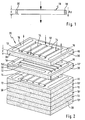
- Figure 1 shows schematically a side view of an inventive Catalyst layer 10 by pressing catalyst material into a thin and large, highly compressed Layer is formed.
- the layer 10 forms a shaped body with a thickness d, which is for example 1 mm.
- Catalyst material becomes a fine-grained catalyst powder or granules are used, the grains of which have a diameter of about 0.5 mm or smaller.
- the pressing takes place, for example at temperatures of approx. 200 ° to 500 ° C.
- the catalyst layer 10 shown is part of a Device for hydrogen generation, not shown, wherein the starting materials of the reaction mixture under pressure essentially perpendicular to the catalyst layer 10 these are fed and pressed through them. At the The reaction mixture experiences flow through the catalyst layer 10 a pressure drop ⁇ p of approx. 100 mbar and more (for example 1 to 4 bar). On the opposite side of the Catalyst layer 10 enter the catalytic reaction products in the sense of the drawn arrow.
- This gas-tight area represents an edge seal 30 which ensures is that the gas the catalyst layer 10 only in the direction of the arrow flows through and not laterally from the catalyst layer 10 exits.
- the catalyst material pressed into a support structure.
- Carrier structure is a network-like matrix that by mixing the at least one catalyst powder with dendritic copper in powder form and pressing this mixture is obtained.
- the dendritic forms Copper a network-like matrix structure, in which the catalyst grains are "built in”.
- the dendritic copper powder leaves even with a relatively low mass fraction of copper powder lightly compress to the total mass of the layer into a net or sinter, has a large surface and is itself catalytically active. By using dendritic Copper powder therefore becomes a stabilizing, fixing and heat distribution network in the micrometer range.
- the catalyst layer 10 has a relatively large area of, for example, 100 cm 2 .
- the volume of catalyst to be flowed through by the reaction mixture is divided into several layers, which are not arranged next to one another, but one behind the other, but connected in parallel.
- Such an arrangement is shown in FIG. 2 and shows a stack 20 comprising a plurality of catalyst layers 10, 10 ′ lying on top of one another, the layers lying at the top in the drawing being shown spaced apart to better illustrate the mode of operation.
- Each catalyst layer 10 has an edge seal 30 on its outer circumference running perpendicular to the stacking direction.
- the catalyst layers 10 also have channels 12, 14, 14 '16 for conducting educts and products of the catalytic reaction.
- educt channels 12 are provided in the catalyst layer which run essentially parallel to the longitudinal edges and which form continuous guide channels perpendicular to the surface plane of the catalyst layer, the educt channels 12 of catalyst layers 10, 10 'lying one above the other being arranged substantially congruently with one another and thus form a guide channel for the starting materials of the reaction mixture which runs through the entire stack 20 from top to bottom.
- a specific reaction mixture is passed through the educt channels 12.
- the reaction mixture comprises alcohol, in particular methanol, and chemically bound hydrogen, advantageously in the form of water.
- the reaction mixture comprises carbon monoxide and hydrogen.
- the reaction mixture comprises a CO-containing gas and an O 2 -containing gas.
- the reaction mixture comprises a combustible starting material and an O 2 -containing gas.
- the reactant channels 12 of each second catalyst layer 10 are in place with essentially parallel to the surface area of the catalyst layer 10 extending distribution channels 14 in connection, which at least part of the through the educt channels 12th entering reaction mixture into the interior of the catalyst layer 10 derive.
- a catalyst layer with a Channel structure used, as in the embodiment 3 is shown.
- the catalyst layer shown in Figure 3 21 has educt channels 22a, 22b and product channels 26, which in their function is principally related with the educt and product channels 12 described in FIG. 2 and 16 correspond.
- Deviating from that shown in Figure 2 The two catalyst layers 10 are spatially separated from one another arranged educt channels 22a, 22b through the distribution channels not in connection with each other, but that of everyone of the feed channels 22a, 22b outgoing distribution channels 24a and 24b extend across the catalyst layer 21, ends however, before the opposite educt channel 22b or Reach 22a.
- each catalyst layer 10 ' product channels 16 configured analogously to the educt channels 12, which are also essentially perpendicular to the surface area each catalyst layer 10 extending guide channels form that with superimposed catalyst layers 10 each congruent with the product channels above or underlying catalyst layer 10, 10 'for lying come.
- an inventive Device for carrying out a heterogeneously catalyzed reaction like hydrogen production the superimposed ones Catalyst layers 10, 10 'thus alternate Modes of operation; in the catalyst layers 10 the educts supplied through the educt channels 12 distributed and via distribution channels 14 over the area of the above and below Distributed catalyst layer where they in the essentially vertical and under a considerable pressure drop flow through.
- catalyst layer 10 ' are the products of the catalytic reaction in collecting channels 14 'collected and the product channels 16 for discharging the Reaction products fed from the stack 20.
- each Catalyst layer feeding, distributing, collecting and discharging the educts or products take over.
- Such more complex Catalyst layers can for example by pressing and Sintering powdered catalyst material on already sintered catalyst layers are produced.
- catalyst layers are provided that are simple and can be produced in a compact manner and for use in hydrogen reactors for catalytic hydrogen production, hydrogen shift stages for CO reduction, carbon monoxide oxidizers and catalytic burners are suitable.
- This configuration of the catalyst becomes a modular design enables, with only small thermal losses and none Large temperature gradients occur, causing an over large volume homogeneous reaction is made possible.
- the the entire catalyst volume can be reached spatially with starting materials, which leads to significantly improved starting dynamics.
- the expert can identify one the respective requirements tailored and related Layer sequence, heat distribution, flow conditions and mechanical Properties such as pressure drop and stability optimized inventive catalyst layer or catalyst layer arrangement produce.
- the edge seal 30 can be manufactured in different ways become. On the one hand, it can be trained that the catalyst powder in the manufacture in the edge area experiences a greater compression and thus essentially one forms a gastight edge seal 30. Furthermore, in one or more others in the edge area of the catalyst powder Materials are mixed in, which are then processed in a post-treatment step the essentially gastight edge seal 30 form. Preferably materials are used here that form a dense layer in a subsequent sintering step. However, it is also possible to use materials that already undergo a transformation under process conditions and therefore when the device is started up for the first time form a substantially gastight edge seal 30.
- edge 30 after Pressing and stacking the catalyst layers 10 on to apply the edge area.
- All can be gas impermeable and temperature stable materials are used.
- Preferably copper or a ceramic material is used.
- the Edge seal 30 can, for example, by dipping or by means of Plasma or flame spraying can be applied. Is possible also applying a solder foil to the finished stack, whereby the solder foil under the influence of heat in the porous body penetrates and then seals it.
- edge seal 30 directly in or on the The edge region of the catalyst layers 10 has the advantage that on an otherwise commonly used solid metal housing can be dispensed with. This can result in both costs as well as the weight of the device can be reduced.
- FIG. 4 A safety optimized device in cut The illustration is shown in FIG. 4.
- a stack 20 of catalyst layers 10, 10 ' is provided.
- This Stack is arranged between two end plates 31, 31 ', wherein in one or both end plates 31, 31 'supply and discharge lines 32 are provided for the media.
- In the embodiment shown are four in the upper end plate 31 respectively Discharge lines 32 shown. This is what it is about However, this is only a basic presentation. Of course can also have a different number of supply and discharge lines 32 are provided. Plus, they don't all have to be arranged in the upper end plate 31, but it can also part or all of the supply and discharge lines 32 in the lower end plate 31 'may be provided.
- All catalyst layers 10, 10 ' have one in the edge region for the sake of simplicity only the edge seal 30 indicated by dashed lines through which the stack 20 against the stack direction against the environment is sealed. Sealing takes place in the stacking direction over the end plates 31, 31 '. For this reason the catalyst layers 10, 10 'are of course also gas-tight be connected to the end plates 31, 31 '. Still is the entire stack 20 is surrounded by a gas-tight film 33, which is also gas-tight with the two end plates 31, 31 ' connected is.
- the film 33 knows at least one with an oxidation catalyst 34 provided opening 35. Through this Opening 35 can fuel gases through possibly existing smallest leaks emerge from the edge seals 30, after complete oxidation with that in the ambient air existing oxygen are released to the environment.
Landscapes
- Chemical & Material Sciences (AREA)
- Organic Chemistry (AREA)
- Chemical Kinetics & Catalysis (AREA)
- Engineering & Computer Science (AREA)
- Combustion & Propulsion (AREA)
- Inorganic Chemistry (AREA)
- General Health & Medical Sciences (AREA)
- Health & Medical Sciences (AREA)
- Manufacturing & Machinery (AREA)
- Sustainable Development (AREA)
- Sustainable Energy (AREA)
- Electrochemistry (AREA)
- General Chemical & Material Sciences (AREA)
- Life Sciences & Earth Sciences (AREA)
- Materials Engineering (AREA)
- Hydrogen, Water And Hydrids (AREA)
- Catalysts (AREA)
- Fuel Cell (AREA)
- Organic Low-Molecular-Weight Compounds And Preparation Thereof (AREA)
Abstract
Description
- Figur 1
- veranschaulicht in stark schematischer Darstellung die Funktionsweise einer erfindungsgemäßen Katalysatorschicht.
- Figur 2
- zeigt in perspektivischer Darstellung eine erfindungsgemäße stapelförmige Anordnung parallel geschalteter Katalysatorschichten.
- Figur 3
- zeigt in perspektivischer Darstellung ein weiteres Ausführungsbeispiel einer einzelnen erfindungsgemäßen Katalysatorschicht.
- Figur 4
- zeigt in stark schematischer Darstellung ein weiteres Ausführungsbeispiel einer erfindungsgemäßen stapelförmigen Anordnung parallel geschalteter Katalysatorschichten im Schnitt.
Claims (12)
- Vorrichtung zur Durchführung einer heterogen katalysierten Reaktion unter Zuführung eines geeigneten Reaktionsgemisches auf einen Katalysator, der aus mehreren aufeinandergestapelten und durch Verpressen von Katalysatormaterial gebildeten dünnen und großflächigen Schichten (10, 10'; 21) besteht, durch die das Reaktionsgemisch unter Druckabfall (Δp) hindurchpreßbar ist, mit Kanälen (12, 14, 14', 16; 22a, 22b, 24a, 24b, 26) zum Leiten von Edukten des Reaktionsgemisches und der Reaktionsprodukte,
dadurch gekennzeichnet,
daß die aufeinandergestapelten Schichten (10, 10'; 21) in Stapelrichtung jeweils von einer Endplatte (31, 31') gegrenzt werden,
daß zumindest in einer der Endplatten (31, 31') Zu- beziehungsweise Abfuhrleitungen (32) vorgesehen sind, die mit den Kanälen (12, 14, 14', 16; 22a, 22b, 24a, 24b, 26) in Strömungsverbindung stehen, und
daß die Schichten (10, 10'; 21) im Randbereich oder auf der quer zur Stapelrichtung verlaufenden Oberfläche eine Randabdichtung (30) aufweisen. - Vorrichtung nach Anspruch 1,
dadurch gekennzeichnet,
daß die aufeinandergestapelten Schichten (10, 10'; 21) von einer gasdichten Folie (33) umgeben sind. - Vorrichtung nach Anspruch 2,
dadurch gekennzeichnet,
daß der Bereich zwischen der Folie (33) und den Schichten (10, 10'; 21) zur Entlüftung zumindest eine mit einem Katalysator (34) versehene Öffnung (35) aufweist. - Vorrichtung nach Anspruch 1,
dadurch gekennzeichnet,
daß das Katalysatormaterial mit einer netzartigen, metallenen Trägerstruktur verpreßt ist. - Vorrichtung nach Anspruch 4,
dadurch gekennzeichnet,
daß die netzartige Trägerstruktur aus dendritischem Kupfer ist. - Verfahren zur Herstellung einer Randabdichtung für eine Vorrichtung gemäß Anspruch 1,
dadurch gekennzeichnet,
daß das Katalysatormaterial im Randbereich eine stärkere Verdichtung erfährt. - Verfahren zur Herstellung einer Randabdichtung für eine Vorrichtung gemäß Anspruch 1,
dadurch gekennzeichnet,
daß dem Katalysatormaterial vor dem Verpressen im Randbereich zumindest ein weiteres Material beigemischt wird, welches nach dem Pressen in einem Nachbehandlungsschritt eine gasdichte Randabdichtung (30) ausbildet. - Verfahren nach Anspruch 7,
dadurch gekennzeichnet,
daß die Schichten (10, 10'; 21) im Anschluß an das Verpressen einer Sinterung unterzogen werden. - Verfahren nach Anspruch 7,
dadurch gekennzeichnet,
daß ein Material beigemischt wird, welches unter Prozeßbedingungen eine gasdichte Randabdichtung (30) ausbildet. - Verfahren zur Herstellung einer Randabdichtung für eine Vorrichtung gemäß Anspruch 1,
dadurch gekennzeichnet,
daß auf die gepreßten, aufeinandergestapelten Schichten (10, 10'; 21) ein gasundurchlässiges, temperaturstabiles Material aufgetragen wird. - Verfahren nach Anspruch 10,
dadurch gekennzeichnet,
daß das Material durch Tauchen, Plasmaspritzen oder Flammspritzen aufgebracht wird. - Verfahren nach Anspruch 10,
dadurch gekennzeichnet,
daß eine Lötfolie auf die gepreßten, aufeinandergestapelten Schichten (10, 10'; 21) aufgebracht wird und daß die Vorrichtung anschließend einer erhöhten Temperatur ausgesetzt wird, wobei die Lötfolie in die Schichten (10, 10'; 21) eindringt und eine gasdichte Randabdichtung (30) ausbildet.
Applications Claiming Priority (2)
| Application Number | Priority Date | Filing Date | Title |
|---|---|---|---|
| DE19944185 | 1999-09-15 | ||
| DE19944185A DE19944185A1 (de) | 1999-09-15 | 1999-09-15 | Vorrichtung zur Durchführung einer heterogen katalysierten Reaktion und Verfahren zu deren Herstellung |
Publications (2)
| Publication Number | Publication Date |
|---|---|
| EP1084747A1 true EP1084747A1 (de) | 2001-03-21 |
| EP1084747B1 EP1084747B1 (de) | 2005-02-02 |
Family
ID=7922097
Family Applications (1)
| Application Number | Title | Priority Date | Filing Date |
|---|---|---|---|
| EP00116572A Expired - Lifetime EP1084747B1 (de) | 1999-09-15 | 2000-08-01 | Vorrichtung zur Durchführung einer heterogen katalysierten Reaktion und Verfahren zu deren Herstellung |
Country Status (3)
| Country | Link |
|---|---|
| US (1) | US6830736B1 (de) |
| EP (1) | EP1084747B1 (de) |
| DE (2) | DE19944185A1 (de) |
Families Citing this family (17)
| Publication number | Priority date | Publication date | Assignee | Title |
|---|---|---|---|---|
| DE19944187A1 (de) * | 1999-09-15 | 2001-03-29 | Xcellsis Gmbh | Gaserzeugungssystem |
| AU2003256422A1 (en) * | 2002-08-15 | 2004-03-03 | Velocys, Inc. | Tethered catalyst processes in microchannel reactors and systems containing a tethered catalyst or tethered chiral auxiliary |
| US7458997B2 (en) * | 2004-04-06 | 2008-12-02 | Angstrom Power Incorporated | Method for making compact chemical reactors |
| US7067217B2 (en) * | 2004-04-06 | 2006-06-27 | Angstrom Power | Compact fuel cell layer |
| US7247281B2 (en) * | 2004-04-06 | 2007-07-24 | Fuelcell Energy, Inc. | Methanation assembly using multiple reactors |
| US7052795B2 (en) * | 2004-04-06 | 2006-05-30 | Angstrom Power | Compact chemical reactor |
| US7241525B2 (en) * | 2004-04-06 | 2007-07-10 | Angstrom Power Inc. | Fuel cell layer with reactor frame |
| US7195652B2 (en) * | 2004-04-06 | 2007-03-27 | Angstrom Power | Method for forming compact chemical reactors with reactor frames |
| US7063910B2 (en) * | 2004-04-06 | 2006-06-20 | Angstrom Power | Compact chemical reactor with reactor frame |
| US20070235174A1 (en) * | 2005-12-23 | 2007-10-11 | Dakhoul Youssef M | Heat exchanger |
| US8033326B2 (en) * | 2006-12-20 | 2011-10-11 | Caterpillar Inc. | Heat exchanger |
| WO2009123638A1 (en) * | 2008-04-04 | 2009-10-08 | Utc Power Corporation | Fuel cell plate having multi-directional flow field |
| DE112011103504T5 (de) * | 2010-10-18 | 2013-11-14 | Velocys Corporation | Laminierte, lecksichere, chemische Prozessoren, Herstellungsverfahren und Betriebsverfahren |
| DE102013205242A1 (de) * | 2013-03-25 | 2014-09-25 | Mahle International Gmbh | Abgaskühler |
| US9755250B2 (en) * | 2013-07-25 | 2017-09-05 | Audi Ag | Method of making a fuel cell component having an interdigitated flow field configuration |
| US12313352B2 (en) | 2019-07-09 | 2025-05-27 | Board Of Trustees Of Michigan State University | Heat exchanger and method of making same |
| DE102020202373A1 (de) | 2020-02-25 | 2021-08-26 | Robert Bosch Gesellschaft mit beschränkter Haftung | Verfahren zur Herstellung eines Brennstoffzellenstapels, Brennstoffzellenstapel |
Citations (5)
| Publication number | Priority date | Publication date | Assignee | Title |
|---|---|---|---|---|
| DE19708472A1 (de) * | 1997-02-20 | 1998-09-24 | Atotech Deutschland Gmbh | Herstellverfahren für chemische Mikroreaktoren |
| US5829517A (en) * | 1996-05-02 | 1998-11-03 | Daimler-Benz Ag | Flow module |
| EP0906890A1 (de) * | 1997-10-02 | 1999-04-07 | dbb fuel cell engines GmbH | Vorrichtung zur Wasserstofferzeugung,Vorrichtung zur Kohlenmonoxid-Verringerung,Vorrichtung zur Kohlenmonoxid-Oxidation,Vorrichtung zum katalytischen Verbrennen und Verfahren zur Herstellung eines Katalysators |
| DE19753720A1 (de) * | 1997-12-04 | 1999-06-10 | Dbb Fuel Cell Engines Gmbh | Vorrichtung zur selektiven katalytischen Oxidation von Kohlenmonoxid |
| DE19825102A1 (de) * | 1998-06-05 | 1999-12-09 | Dbb Fuel Cell Engines Gmbh | Verfahren zur Herstellung eines kompakten katalytischen Reaktors |
Family Cites Families (14)
| Publication number | Priority date | Publication date | Assignee | Title |
|---|---|---|---|---|
| US4333986A (en) * | 1979-06-11 | 1982-06-08 | Sumitomo Electric Industries, Ltd. | Diamond sintered compact wherein crystal particles are uniformly orientated in a particular direction and a method for producing the same |
| US4526845A (en) * | 1981-09-30 | 1985-07-02 | United Technologies Corporation | Molten carbonate fuel cell integral matrix tape and bubble barrier |
| GB8521953D0 (en) | 1985-09-04 | 1985-10-09 | Johnson Matthey Plc | Catalytic hydrogen generator |
| US5209906A (en) * | 1991-05-10 | 1993-05-11 | Her Majesty The Queen In Right Of Canada, As Represented By The Minister Of National Defence | Modular isothermal reactor |
| US5316747A (en) * | 1992-10-09 | 1994-05-31 | Ballard Power Systems Inc. | Method and apparatus for the selective oxidation of carbon monoxide in a hydrogen-containing gas mixture |
| EP0611594A1 (de) * | 1993-02-17 | 1994-08-24 | Siemens Aktiengesellschaft | Katalysator zur Umsetzung von Reaktanten eines Gasgemisches |
| US5534328A (en) * | 1993-12-02 | 1996-07-09 | E. I. Du Pont De Nemours And Company | Integrated chemical processing apparatus and processes for the preparation thereof |
| US5580497A (en) * | 1993-04-16 | 1996-12-03 | Amoco Corporation | Oxygen ion-conducting dense ceramic |
| EP0687648B1 (de) | 1994-06-15 | 1998-09-16 | dbb fuel cell engines GmbH | Zweistufige Methanol-Reformierung |
| DE19654361A1 (de) * | 1996-12-24 | 1998-06-25 | Behr Gmbh & Co | Reaktor in Stapelbauweise |
| US5908544A (en) * | 1997-09-04 | 1999-06-01 | Gould Electronics, Inc. | Zinc-chromium stabilizer containing a hydrogen inhibiting additive |
| US6132895A (en) * | 1998-03-09 | 2000-10-17 | Motorola, Inc. | Fuel cell |
| US6200696B1 (en) * | 1999-02-16 | 2001-03-13 | Energy Research Corporation | Internal reforming fuel cell assembly with simplified fuel feed |
| US6387558B1 (en) * | 1999-02-18 | 2002-05-14 | Toyota Jidosha Kabusiki Kaisha | Fuel cell, separator for the same and method for distributing gas in fuel cell |
-
1999
- 1999-09-15 DE DE19944185A patent/DE19944185A1/de not_active Ceased
-
2000
- 2000-08-01 DE DE50009401T patent/DE50009401D1/de not_active Expired - Lifetime
- 2000-08-01 EP EP00116572A patent/EP1084747B1/de not_active Expired - Lifetime
- 2000-09-15 US US09/662,850 patent/US6830736B1/en not_active Expired - Fee Related
Patent Citations (5)
| Publication number | Priority date | Publication date | Assignee | Title |
|---|---|---|---|---|
| US5829517A (en) * | 1996-05-02 | 1998-11-03 | Daimler-Benz Ag | Flow module |
| DE19708472A1 (de) * | 1997-02-20 | 1998-09-24 | Atotech Deutschland Gmbh | Herstellverfahren für chemische Mikroreaktoren |
| EP0906890A1 (de) * | 1997-10-02 | 1999-04-07 | dbb fuel cell engines GmbH | Vorrichtung zur Wasserstofferzeugung,Vorrichtung zur Kohlenmonoxid-Verringerung,Vorrichtung zur Kohlenmonoxid-Oxidation,Vorrichtung zum katalytischen Verbrennen und Verfahren zur Herstellung eines Katalysators |
| DE19753720A1 (de) * | 1997-12-04 | 1999-06-10 | Dbb Fuel Cell Engines Gmbh | Vorrichtung zur selektiven katalytischen Oxidation von Kohlenmonoxid |
| DE19825102A1 (de) * | 1998-06-05 | 1999-12-09 | Dbb Fuel Cell Engines Gmbh | Verfahren zur Herstellung eines kompakten katalytischen Reaktors |
Also Published As
| Publication number | Publication date |
|---|---|
| DE50009401D1 (de) | 2005-03-10 |
| EP1084747B1 (de) | 2005-02-02 |
| DE19944185A1 (de) | 2001-03-29 |
| US6830736B1 (en) | 2004-12-14 |
Similar Documents
| Publication | Publication Date | Title |
|---|---|---|
| EP1019183B1 (de) | Vorrichtung zur durchführung einer heterogen katalysierten reaktion und verfahren zur herstellung eines katalysators | |
| EP1084747B1 (de) | Vorrichtung zur Durchführung einer heterogen katalysierten Reaktion und Verfahren zu deren Herstellung | |
| DE19813053C2 (de) | Reaktoreinheit für eine katalytische chemische Reaktion, insbesondere zur katalytischen Methanolreformierung | |
| DE10230342C1 (de) | Membranmodul zur Wasserstoffabtrennung | |
| WO2002040619A2 (de) | Verfahren und vorrichtung zur reduktion des kohlenmonoxidgehalts in einem wasserstoffhaltigen gasstrom, sowie reformeranlage | |
| DE102008031092A1 (de) | Verfahren und Vorrichtung zur Erzeugung von Wasserstoff | |
| DE19753720A1 (de) | Vorrichtung zur selektiven katalytischen Oxidation von Kohlenmonoxid | |
| DE19955929C2 (de) | Verfahren zur autothermen Reformierung eines Kohlenwasserstoffs | |
| EP1116518A2 (de) | Reformierungsreaktor in Schichtbauweise | |
| DE10136768B4 (de) | Brennstoffzellenanlage mit zwei Umformeinheiten zur katalytischen Dekomposition und Verfahren zur katalytischen Dekomposition | |
| DE19906672C2 (de) | Vorrichtung zur Durchführung einer katalytischen Reaktion | |
| DE10028865A1 (de) | Vorrichtung zur katalytischen Wasserstofferzeugung aus Kohlenwasserstoffen | |
| EP1216200B1 (de) | Gaserzeugungssystem | |
| DE19904398B4 (de) | Lanze | |
| DE19907665A1 (de) | Vorrichtung zur Ausnutzung bei einer katalytischen Reaktion enstehender Wärme | |
| DE10046692A1 (de) | Vorrichtung zur Verdampfung einer Flüssigkeit | |
| EP1084990B1 (de) | Vorrichtung zum Erwärmen und/oder Umsetzen wenigstens eines Mediums | |
| EP4445072A1 (de) | Eigensicherer katalytischer rekombinator und hausenergiezentrale und verfahren zu deren betrieb | |
| EP1350562B1 (de) | Vorrichtung zur Kombination zweier heterogen katalysierter Reaktionen und Verfahren zur Herstellung der Vorrichtung | |
| DE69404104T2 (de) | Verfahren zur Verringerung der Zündtemperatur einer exothermen katalytischen Reaktion | |
| EP1110906B1 (de) | Vorrichtung zur selektiven katalytischen Oxidation von Kohlenmonoxid | |
| DE102024113650B3 (de) | Reaktor zur Durchführung von exothermen Reaktionen sowie Verwendung und Verfahren zum Betreiben eines solchen Reaktors | |
| DE19901301C1 (de) | Vorrichtung zur Kombination zweier heterogen katalysierter Reaktionen | |
| DE10151519B4 (de) | Reaktor für eine katalytische Reaktion | |
| DE10033596B4 (de) | Vorrichtung zur Durchführung einer festkörperkatalysierten Reaktion |
Legal Events
| Date | Code | Title | Description |
|---|---|---|---|
| PUAI | Public reference made under article 153(3) epc to a published international application that has entered the european phase |
Free format text: ORIGINAL CODE: 0009012 |
|
| AK | Designated contracting states |
Kind code of ref document: A1 Designated state(s): DE FR GB IT |
|
| AX | Request for extension of the european patent |
Free format text: AL;LT;LV;MK;RO;SI |
|
| 17P | Request for examination filed |
Effective date: 20010213 |
|
| AKX | Designation fees paid |
Free format text: DE FR GB IT |
|
| RAP1 | Party data changed (applicant data changed or rights of an application transferred) |
Owner name: BALLARD POWER SYSTEMS AG |
|
| 17Q | First examination report despatched |
Effective date: 20040521 |
|
| GRAP | Despatch of communication of intention to grant a patent |
Free format text: ORIGINAL CODE: EPIDOSNIGR1 |
|
| GRAS | Grant fee paid |
Free format text: ORIGINAL CODE: EPIDOSNIGR3 |
|
| GRAA | (expected) grant |
Free format text: ORIGINAL CODE: 0009210 |
|
| AK | Designated contracting states |
Kind code of ref document: B1 Designated state(s): DE FR GB IT |
|
| REG | Reference to a national code |
Ref country code: GB Ref legal event code: FG4D Free format text: NOT ENGLISH |
|
| REF | Corresponds to: |
Ref document number: 50009401 Country of ref document: DE Date of ref document: 20050310 Kind code of ref document: P |
|
| GBT | Gb: translation of ep patent filed (gb section 77(6)(a)/1977) |
Effective date: 20050427 |
|
| PLBE | No opposition filed within time limit |
Free format text: ORIGINAL CODE: 0009261 |
|
| STAA | Information on the status of an ep patent application or granted ep patent |
Free format text: STATUS: NO OPPOSITION FILED WITHIN TIME LIMIT |
|
| ET | Fr: translation filed | ||
| 26N | No opposition filed |
Effective date: 20051103 |
|
| REG | Reference to a national code |
Ref country code: FR Ref legal event code: CD Ref country code: FR Ref legal event code: TP |
|
| PGFP | Annual fee paid to national office [announced via postgrant information from national office to epo] |
Ref country code: DE Payment date: 20090821 Year of fee payment: 10 Ref country code: GB Payment date: 20090827 Year of fee payment: 10 |
|
| PGFP | Annual fee paid to national office [announced via postgrant information from national office to epo] |
Ref country code: IT Payment date: 20090820 Year of fee payment: 10 |
|
| GBPC | Gb: european patent ceased through non-payment of renewal fee |
Effective date: 20100801 |
|
| REG | Reference to a national code |
Ref country code: FR Ref legal event code: ST Effective date: 20110502 |
|
| PG25 | Lapsed in a contracting state [announced via postgrant information from national office to epo] |
Ref country code: IT Free format text: LAPSE BECAUSE OF NON-PAYMENT OF DUE FEES Effective date: 20100801 |
|
| REG | Reference to a national code |
Ref country code: DE Ref legal event code: R119 Ref document number: 50009401 Country of ref document: DE Effective date: 20110301 |
|
| PG25 | Lapsed in a contracting state [announced via postgrant information from national office to epo] |
Ref country code: FR Free format text: LAPSE BECAUSE OF NON-PAYMENT OF DUE FEES Effective date: 20100831 Ref country code: DE Free format text: LAPSE BECAUSE OF NON-PAYMENT OF DUE FEES Effective date: 20110301 |
|
| PG25 | Lapsed in a contracting state [announced via postgrant information from national office to epo] |
Ref country code: GB Free format text: LAPSE BECAUSE OF NON-PAYMENT OF DUE FEES Effective date: 20100801 |
|
| PGFP | Annual fee paid to national office [announced via postgrant information from national office to epo] |
Ref country code: FR Payment date: 20090914 Year of fee payment: 10 |